BAYKON TX12 User manual
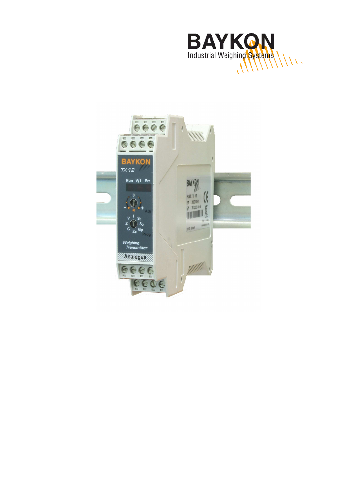
TX12
Weight Transmitter
Technical Manual
Rev 1.1
1
S
AFETY
I
NSTRUCTIONS
CAUTION! READ THIS MANUAL BEFORE OPERATING OR SERVICING THIS E UIPMENT. FOLLOW THESE
INSTRUCTIONS CAREFULLY. SAVE THIS MANUAL FOR FUTURE REFERENCE. DO NOT ALLOW
UNTRAINED PERSONNEL TO OPERATE, CLEAN, INSPECT, MAINTAIN, SERVICE, OR TAMPER WITH THIS
E UIPMENT. ALWAYS DISCONNECT THIS E UIPMENT FROM THE POWER SOURCE BEFORE CLEANING
OR PERFORMING MAINTENANCE. CALL BAYKON ENGINEERING FOR PARTS, INFORMATION, AND
SERVICE.
WARNING! ONLY PERMIT UALIFIED PERSONNEL TO SERVICE THIS E UIPMENT. EXERCISE CARE
WHEN MAKING CHECKS, TESTS AND ADJUSTMENTS THAT MUST BE MADE WITH POWER ON. FAILING
TO OBSERVE THESE PRECAUTIONS CAN RESULT IN BODILY HARM.
WARNING! FOR CONTINUED PROTECTION AGAINST SHOCK HAZARD CONNECT TO PROPERLY
GROUNDED OUTLET ONLY. DO NOT REMOVE THE GROUND PRONG.
WARNING! DISCONNECT ALL POWER TO THIS UNIT BEFORE REMOVING ANY CONNECTION, OPENING
THE ENCLOSURE OR SERVICING.
WARNING! BEFORE CONNECTING/DISCONNECTING ANY INTERNAL ELECTRONIC COMPONENTS OR
INTERCONNECTING WIRING BETWEEN ELECTRONIC E UIPMENT ALWAYS REMOVE POWER AND WAIT
AT LEAST THIRTY (30) SECONDS BEFORE ANY CONNECTIONS OR DISCONNECTIONS ARE MADE.
FAILURE TO OBSERVE THESE PRECAUTIONS COULD RESULT IN DAMAGE TO OR DESTRUCTION OF THE
E UIPMENT OR BODILY HARM.
CAUTION! OBSERVE PRECAUTIONS FOR HANDLING ELECTROSTATIC SENSITIVE DEVICES.
RIGHTS AND LIABILITIES
No part of this publication may be reproduced, stored in a retrieval system, or transmitted in any form or by any
means, mechanical, photocopying, recording, or otherwise, without the prior written permission of BAYKON A.S.
No patent liability is assumed with respect to the use of the information contained herein. While every precaution
has been taken in the preparation of this book, BAYKON assumes no responsibility for errors or omissions. Neither
is any liability assumed for damages resulting from the use of the information contained herein.
The information herein is believed to be both accurate and reliable. BAYKON, however, would be obliged to be
informed if any errors occur. BAYKON cannot accept any liability for direct or indirect damages resulting from the
use of this manual.
BAYKON reserves the right to revise this manual and alter its content without notification at any time.
Neither BAYKON nor its affiliates shall be liable to the purchaser of this product or third parties for damages,
losses, costs, or expenses incurred by purchaser or third parties as a result of: accident, misuse, or abuse of this
product or unauthorized modifications, repairs, or alterations to this product, or failure to strictly comply with
BAYKON operating and maintenance instructions.
BAYKON shall not be liable against any damages or problems arising from the use of any options or any
consumable products other than those designated as Original BAYKON Products.
NOTICE: The contents of this manual are subject to change without notice.
All rights reserved. Copyright © 2012 by BAYKON A.Ş. Istanbul, Turkey
BAYKON A.Ş.
Kimya Sanayicileri Organize SB Organik Cad. No:31 Tepeören, 34956 İstanbul, TURKEY
Tel : +90 216 593 26 30 (pbx) Fax : +90 216 593 26 38 http://www.baykon.com
2
1. F
RONT
V
IEW
,
F
EATURES AND
S
PECIFICATIONS
Microcontroller based analog load cell transmitter TX12 has very high accuracy and long
term stability with its high tech design. Its high performance electronic calibration via
RS232C serial port without any test weight and fast calibration without measuring output
signal give big advantage to the users for calibration scales.
This high tech instrument gives the system designers a lot of advantages to increase the
system reliability and to reduce the installation and service times. Besides the traditional
analog output adjustment with any test weight, the electronic calibration eCal and fast
calibration with 20% Max. test load reduces the calibration time. All instruments’ analog
outputs are matched in the production to perform calibration at PLC and for changing the
instrument without recalibration in service.
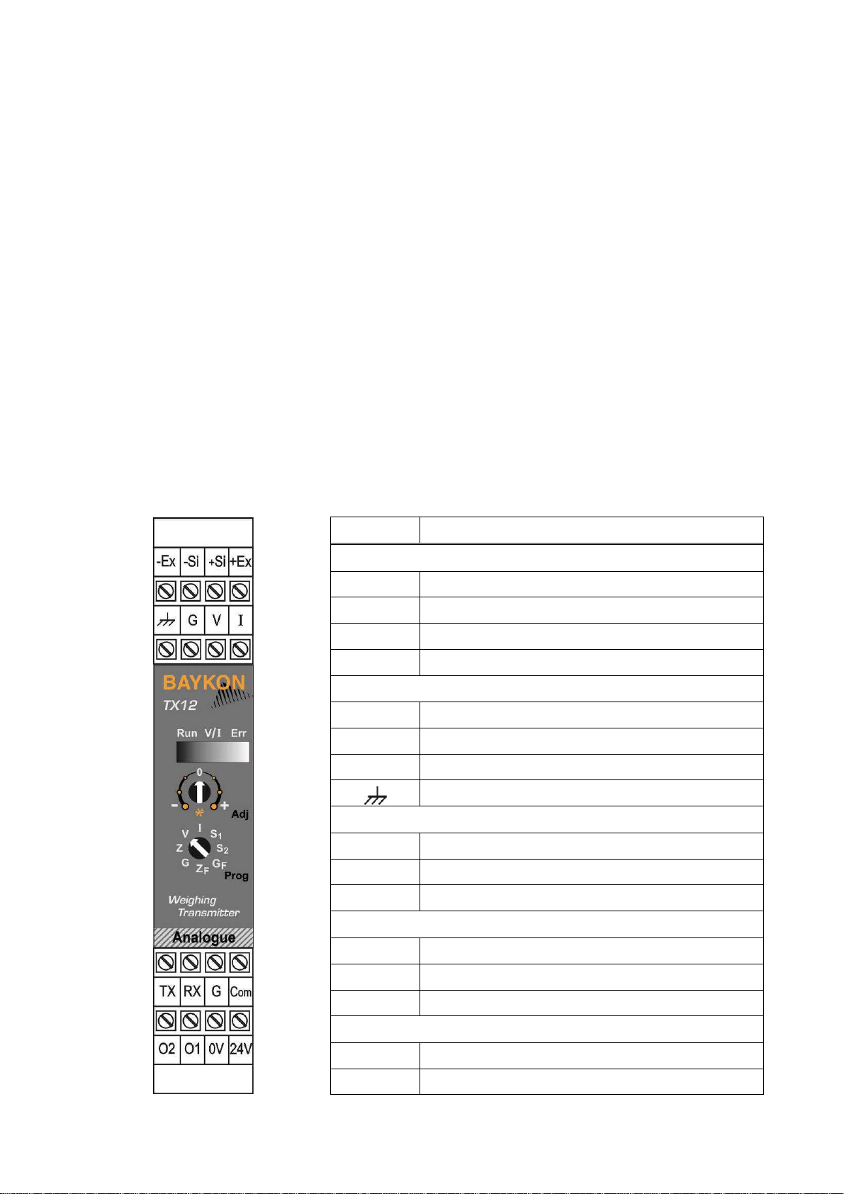
There are 8 positioned rotary switches and annunciator LED’s in front of the instrument.
The front view and pin descriptions of TX12 is shown below.
Pin Name
Defini ion
LOAD CELL CONNECTION
- Ex - Excitation
+ Ex + Excitation
- Si - Signal
+ Si + Signal
ANALOGUE OUTPUT
I
Current output
V Voltage output
G GND
Shield and Protective ground
SERIAL CONNECTION
TX TXD ( RS232C )
RX RXD ( RS232C )
G Ground ( RS232C )
SETPOINT CONNECTION
O1 Digital output 1
O2 Digital output 2
Com Digital outputs common
POWER SUPPLY
24V +24VDC
0V 0VDC
3
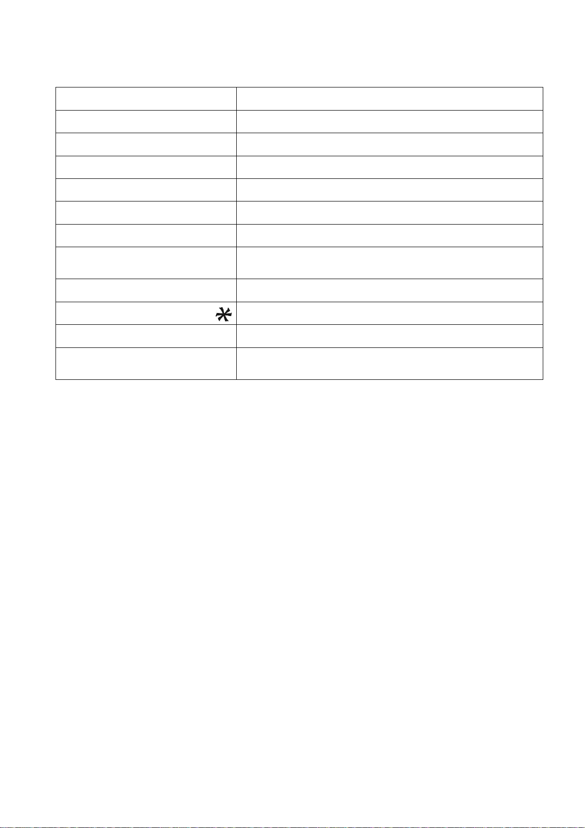
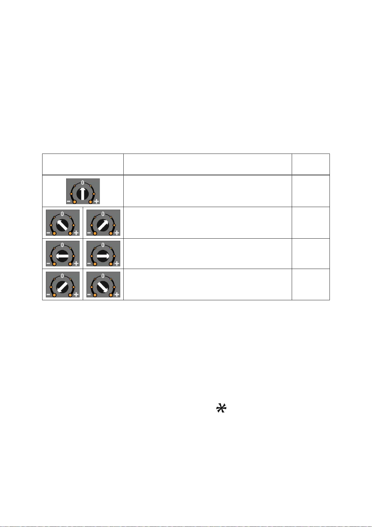
Meanings of rotary switchs’ positions are;
Programming (Prog) switch V Voltage output type run
(refer to page 7)
I
Current output type run
(refer to page 7)
S1
Setpoint 1 adjustment
(refer to page 11)
S2 Setpoint 2 adjustment
(refer to page 11)
Z Zero adjustment
(refer to page 8)
G Gain adjustment with test weight
(refer to page 8)
ZF Fast zero adjustment
(refer to page 9)
GF
Fast gain adjustment with 20% test
weight of Maximum scale capacity
(refer to page 10)
Adjustment (Adj) switch 0 Operation ( Run )
OK in set-up
Others
Set-up and adjustment. Refer to table in step 7
LED’s
Annunciator LED’s ( Run, Output
type
, Error ).
Refer to Section 5
Fea ures
•Minimized zero and span drifts because of its microcontroller technology and high
accurate, very low temperature drift 24 bits ADC and 16 bits DAC converters.
•Long time stability and low temperature drifts eliminates the frequent readjustment
period.
•Very easy and user friendly digital adjustment via rotary switches located on the front
of the instrument.
•Programmable digital adaptive anti-vibration filter to minimize environmental
vibrations.
•eCal electronic calibration without weights and digital filter adjustment via RS232C
port and xFace PC software.
•Fast calibration feature to reduce the adjustment time and to minimize adjustment
error.
•Calibration at PLC does not require readjustment after changing instrument because
of matching in the production.
•2 pcs free relay contact output for alarm or controlling valves, gate etc.

4
TECHNICAL SPECIFICATIONS
Analogue input range 0 mV to 20 mV
Min. input range < 1 mV
Linearity < % 0.01
Temperature drift < 0.007 % FSR / ºC
Converters
24 bit Delta-Sigma ratiometric ADC with integral analog and
digital filters
16 bit very low drift DAC
Internal resolutions 16 000 000 counts ADC
External resolution Analogue output changes up to 65000 steps
Calibration
With rotary switches in the front with any test load.
Fast calibration with 20% Max.
Electronic calibration via PC.
Preadjusted instrument for calibration at PLC
Digital Filter Programmable 3 step adjustable digital adaptive filter.
Analogue outputs Current output for 0-20 mA and 4-20 mA or
voltage output for 0 – 5 V and 0-10 V.
Max. cable length 300 meter
Max. load resistance
(current output) 500 Ω
Set point 2 pcs free programmable setpoints.
Digital Output 2 relay contacts for setpoints, 230 VAC or 30 VDC, 1 A.
Load cell excitation 5 VDC
Number of Load Cells Up to 4 units of 350 Ω or 12 units of 1100 Ω (min. 85 Ω)
Power supply 12 to 28 VDC 0.2 A
Operation Temperature Between -10°C and +45°C at 85% RH max, non-condensing
EMC Immunity Class E2
Enclosure Polyamide, for DIN-rail mount, IP20
Dimensions Front Width:22,5 mm, Front Length: 99 mm , Height:114,5mm

5
2. I
NSTALLATION AND
C
OMMISSIONING
Recommenda ions
Warning: Please care the following warnings for designing the control cabinet which will
increase your system reliability.
The control cabinet should be designed so that instrument can operate safely. The panel
should be placed clean area, not getting direct sun light if possible, with a temperature
between -10 ºC and +40 ºC, humidity not exceeding 85% non-condensing. All external
cables should be installed safely to avoid mechanical damages.
TX12 instruments are very low level signal measuring instruments. To avoid electrical noise,
TX12 should be separated from the equipments that produce electrical noise. Preferable use
metal cabinet against radio frequency interference and the cabinet shall be connected to
ground against the electromagnetic disturbances. Load cell cable and analog output cable
trays must be separated from others, if possible. If there are noise-generating equipments
such as heavy load switches, motor control equipments, inductive loads etc., please be
careful against the EMC interference in the cabinet. Connect parallel reverse diodes to the
DC inductive loads like relays, solenoids etc. to minimize voltage peaks on the DC power
lines.
All load cell and analogue output cables coming to the control cabinet shall be shielded.
Warning: Control cabinet design and proper installation increases reliability and
performance of the instrument. Please do not forget that the instrument must be powered off
before inserting or removing any peripheral connector.
Follow the installation and commissioning steps described below carefully to prevent
unwanted results after installation.
S ep 1 Mechanical Ins alla ion
The place where you will use/install your instrument should be clean, not getting direct
sunlight if possible, with a temperature between -10ºC and +40ºC, 85% maximum relative
humidity non-condensing. Install the instrument on the DIN rail in the cabinet. The
instrument mechanical drawing is;

6
S ep 2 Load Cell Connec ion
The load cell wiring should be made carefully before energizing to avoid damages to the
instrument and load cells. The input resistance of the load cells that you want to connect
should be more than 85 Ω.
Pin Name
Load Cell Cable
+Ex
+ Excitation
-
Ex
-
Excitation
+Si
+ Signal
-
Si
-
Signal
Shield
S ep 3 Analogue Ou pu Connec ion
Only one of the analog output types can be used at the same time and has to be selected in
the setup type. Install the analog output measuring instrument for adjustment, if need be.
Pin Name Defini ion
I
Current Output
V Voltage Output
G GND
Shield
Current output connection
Voltage output connection

7
S ep 4 Changing he Analogue Ou pu
TX12 sets its analog output according to the table below at power on. Turn the programming
switch and connect TXD and RXD pins as indicated in the table below before power on
the instrument to set analog output type and its signal level.
Analogue
Ou pu Range Prog. Swi ch Posi ion TXD & RXD pins V/
I
LED
4 - 20 mA
Open circuited On
0 - 20 mA Short circuited Off
0 - 10 VDC
Open circuited Flash
0 - 5 VDC Short circuited Blinking
You can also set the Analog output type after power on as;
- Turn the programming switch to the analog output type ( to V or
I
position )
- Connect or disconnect TXD and RXD pins according the table above to set the
output range.
- Turn the adjustment switch to the position. After 2 seconds turn in to the
“ 0 “ position back ( if the instrument is powered on before ).
The analogue output type can be followed by the V/
I
LED on front of the instrument after
running it ( refer to table above ) .
After set up the instrument’s analog output according to the table above go to the next step.
S ep 5 Energize he Ins rumen
Check last time the followings before energizing the instrument.
- Check Mechanical installation, grounding, load cell connection and power
supply connection.
- Check the analogue output set up described in step 4.
- The analogue output cabling should be done for the same analogue output
type.
- The adjustment (Adj) rotary switch shall be at “ 0 “ position.
If everything is correct energize the instrument.
8
S ep 6 Zero and Gain Adjus men s
By Changing ou pu value wi h ro ary swi ch:
To start the adjustment the programming switch should be at analog output type position, V
or
I
. Z and G positions of the programming switch are used for performing zero and gain
adjustments in sequence. Analog output is changed by turning the adjustment switch as
described in the table below.
Adjus men ro ary
swi ch posi ion Ro ary swi ch descrip ion Run LED
Do not change, operation On
Decrease ( - ) / Increase ( + ) in slow steps Flash
Decrease ( - ) / Increase ( + ) in medium steps Flash
Decrease ( - ) / Increase ( + ) in big steps Flash
RUN LED flashes to indicate the instrument is not in operation.
Zero Adjus men
- Connect the measurement instrument to the analog output.
- Unload the scale.
- Turn the programming switch to the Z position from the analog output type
position.
- Increase or decrease the analog output by adjustment rotary switch. Never
bring the adjustment switch position to position in this adjustment. The
adjustment switch will be at “ 0 ” position at the end of the adjustment.
- Turn the programming switch to analog output type position ( V or
I
position )
to start the operation or to the G position to start gain adjustment.

9
Gain Adjus men
- Connect the measurement instrument to the analog output.
- Load the scale.
- Calculate the analog output value should be calculated for the applied load.
The analog output value at any loading is;
Analog Output
=
Minimum output
+
Maximum output
–
Minimum output
*
Load
Scale capacity
For example, for 100 kg scale capacity , 4 – 20 mA output range, and 25 kg
load, the analog output current will be ;
I
out
= 4 + (( 20 – 4 ) / 100 ) * Load = 4 + 0.16 * Load = 4 + 0.16 * 25 = 8 mA
The 0 – 10 VDC analog output voltage will be:
V
out
= 0 + (10 / 100 ) * 25 kg = 0,1 * 25 = 2.5 VDC
- Turn the adjustment switch to the G position from the analog output type
position you set before.
- Increase or decrease the analog output by adjustment rotary switch to the
calculated output value.
Never bring the adjustment switch position to position in this adjustment.
The adjustment switch will be at “ 0 ” position at the end of the adjustment.
- Turn the programming switch to analog output type position for operation ( to V
or
I
position ).
Important note: The instrument saves 4 different adjustments in its memory for the voltage
and current outputs and their ranges. Changing the analog output type automatically set the
adjustment before of that output range.
Fas adjus men o nominal ou pu range :
You may perform fast adjustment method if you will set zero and gain to analog output
nominal values. This feature gives advantage to the instrument for small and medium
capacity weighing systems’ fast and easy adjustment.
Fas Zero Adjus men :
- Unload the scale.
- Turn the programming switch to ZF position.
- Turn the Adj. switch to position and turn it back to “ 0 “ position 2
seconds later.
- Turn the programming switch to analog output type position to start operation
or to GF position for gain adjustment.
For example, for 4 – 20 mA range and for 100 kg capacity scale, unload the scale and
perform fast adjustment to set the output to 4 mA.

10
Fas Gain Adjus men :
- Load the scale to the 20% of the maximum capacity ( if scale capacity is
100 kg, load 20 kg ).
- Turn the programming switch to GF position.
- Turn the Adj. switch to position and turn it back to “ 0 ” position
2 seconds later.
- Turn the programming switch to analog output type position for operation.
For example, for 4 – 20 mA range and for 100 kg capacity scale, load the scale 20 kg test
weight and perform fast gain adjustment to set the output to 7,2 mA at this load. The output
will be 20 mA at 100 kg loading.
eCal Elec ronic Adjus men via RS232 :
High capacity tanks’ and silos’ adjustment are very difficult in practice and takes very long
time. You may earn a lot of time by eCal adjustment by entering the theoretical scale and
load cell values to the instrument instead of loading the scale. Because of the production
process of TX12, eCal accuracy is very high. The only error comes from the load cell
sensitivity accuracy and gravity difference between the load cell place of the production and
the usage.
Adjustment with eCal is performed via RS232 port of the instrument by entering the scale
and load cell data. Refer to Section 4.
If you want to increase the eCal accuracy you have to enter the corrected load cell sensitivity
instead of the sensitivity value on the load cell production test certificate.
Adjus men a PLC:
All instruments are adjusted in the production to operate in its analog output range between
0 mV and 10 mV load cell signal as default. For example if the instrument is at factory
default values, and programmed to operate 4 – 20 mA output range, the output will be 4 mA
at 0 mV load cell signal and will be 20 mA at 10 mV load cell signal.
Changing the TX12 instrument is not required recalibration because of matching instruments
in production at Baykon.
Warning: If the instrument is adjusted before and its factory defaults are changed, you
should load factory defaults with x ace.
S ep 7 Tes ing he Scale Performance
You have to check your scale performance by testing the scale eccentricity, scale linearity at
loading up to maximum loading value, repeatability etc. before using it.

11
S ep 8 Se poin Connec ion
TX12 has 2 free relay contact output. These outputs can be connected to maximum 230 VAC
or maximum 30 VDC, maximum 1 A loads. Reverse diode connection to the DC loads is
recommended to increase the relay contact life and to reduce the disturbances. Outputs
connection is;
S ep 9 Se poin Adjus men
The instrument closes the relay contacts if the weight value higher than the adjusted
setpoint. These contact signals can be used to stop charging or discharging or produce
alarm signal. You can apply two methods to adjust setpoints.
Adjus men o he Load on he Scale :
The setpoint can be adjusted to the load value on the scale as;
- Load the scale to the value you want to produce setpoint signal.
- Turn the programming switch to S1 ( or S2 ) position from operation position
( from V or
I
position ).
- Turn the Adj. switch to positions position and turn it back to “ 0 “ position
2 seconds later.
- Turn the programming switch to analog output type position for operation ( V
or
I
position ) or to other setpoint position to adjust it.
Adjus men by measuring he analog ou pu :
You can adjust the setpoint by measuring the analogue output value without loading the
scale as; - Connect the measuring instrument to the analog output.
- Turn the programming switch to S1 ( or S2 ) position from operation position
( from V or
I
position ).
- Increase or decrease the analog output by adjustment rotary switch ( refer to
table in Step 6 ). Do not bring the adjustment switch position to position in
this adjustment. The adjustment switch will be at “ 0 “ position at the end of
the adjustment.
- Turn the programming switch to analog output type position to start operation
( V or
I
position ) or to other setpoint position to adjust it.

12
3. O
PERATION
There are 3 LEDs and 2 rotary switches on the front panel of TX12. The rotary switches
are being used for adjustment as described in section 2 and the LEDs have different
meanings in operation and setup type as indicated below;
Analogue
Ou pu
Range
Prog. Swi ch
posi ion
Adj. Swi ch
posi ion TXD & RXD pins
V/
I
LED
( after power on )
4 - 20 mA
Open circuited On
0 - 20 mA Short circuited Off
0 - 10 VDC
Open circuited Flash
0 - 5 VDC Short circuited Blinking
The status of the LEDs in the operation type is given in the table below. Refer to Section 5
in case of the Err LED turns on.
The analogue output signal also gives information about the status of the system and the
weighing process to inform PLC as ;
Condi ion
4
-
20 mA
ou pu
0
-
20 mA
ou pu
0
–
10 V
ou pu
0
–
5
V
ou pu
Operation X X X X
Programming X X X X
The weight is more than the range
( Over signal to PLC ) 24 mA 24 mA 11 V 5,5 V
The weight is under than the zero range
(Under signal to PLC ) 0 mA 0 mA -4.0 V -4.0 V
“Error” signal to PLC 0 mA 0 mA 0 V 0 V
“ADC is out of operating range” error to PLC 24 mA 24 mA 11 V 5,5 V
13
4. P
ROGRAMMING BY
PC
S
OFTWARE
TX12 has RS232C serial interface to perform eCal electronic calibration and to adjust filter,
setpoint values and to follow status by using xFace software installed on a PC.
For installing the xFace follow the steps described in the Readme.txt file in the eCal set up
directory.
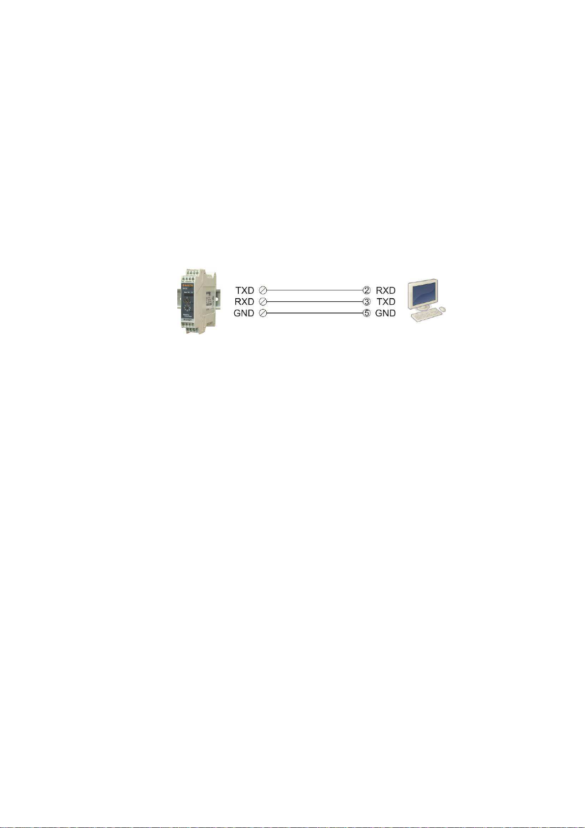
For programming instrument via xFace follow the instructions below;
1. Power off the instrument.
2. Connect the instrument to PC as shown below to use xFace software and run the
xFace. Select TX12 and press “OK” button.
3. Select the analog output type, if you will change.
4. Adjust the filter value if need be.
5. Enter total load cell capacity, scale capacity and estimated dead load if you will not
perform fast zero adjustment by button on the monitor.
6. Press “Write eCal Data to Transmitter” button on the monitor to perform eCal.
7. Unload the scale and Press “ eCal with Zero Adjustment “ button on the monitor if you
will perform zero adjustment with the load cell signal when the scale is unloaded.
8. Power off the instrument, disconnect the PC and bring the programming switch to the
analog output type position and apply the connection between TXD and RXD pins
which is described in the table on page 7 to set the analog output type.
9. Turn the adjustment switch position to “ 0 “ position.
10.Power on the instrument for operation.
After performing eCal as described in the software, check the performance of your system.
You may adjust to instrument to factory default by xFace, if it is changed before.
5.
E
C
AL
A
DJUSTMENT FROM
PLC
Refer to “TX12 Programming via RS232C” document at Baykon web site.

14
6. T
ROUBLE
S
HOOTING
The type TX12 amplifier has been designed as a very reliable and virtually error free
instrument. However if an error occurs, do not attempt to repair the equipment before you
understand what caused the error. Note the status of the front panel LEDs, and try to find the
problem with the help of the table given below. Don’t let unauthorized people interfere with
the instrument.
FRONT PANEL LEDS DEFINITION
Run V/
I
Err
Off Off Off - No power
- Board failure
On On Off - Operation in 4 – 20 mA output type.
On Off Off - Operation in 0 – 20 mA output type.
On Flash Off - Operation in 0 – 10 VDC output type.
On Blinking Off - Operation in 0 – 5 VDC output type.
On X On
- Input signal is out of range
- Calibration needed.
- Check output circuit and cabling.
- Board failure
The analogue output also give additional information about the weighing system as
described in Section 3.

15
Declara ion of Conformi y
We;
BAYKON ENDÜSTRİYEL KONTROL SİSTEMLERİ SAN. VE TİC. A.Ş.
Kimya Sanayicileri Or
ganize Sanayi Bölgesi Organik Cad. No:31
34956 Tepeören Tuzla/İSTANBUL TURKEY
to which this declaration relates, is in conformity with the following standard(s) or other
normative document(s).
EC Directive: Applicable Standards:
Low Voltage Directive (LVD): (2006/95/EC) EN 60950-1
Electromagnetic Compatibility (EMC): (2004/108/EC) EN 61326-1
Baykon, July 2013
Muhammed YALÇINKAYA
Sedat AYDEMİR
General Manager
uality Assurance Manager
Table of contents
Other BAYKON Transmitter manuals


