RADIXON Excalibur Sigma User manual

WiNRADiO®
by RADIXON
®
WR-G65DDC
EXCALIBUR SIGMA
TM
Software-Defined Communications Receiver
User’s Guide
Ver. 1.07

WiNRADiO G65DDC User’s Guide
2
Published by
Radixon Group Pty. Ltd.
45 - 47 Islington Street, Collingwood, Victoria 3066 Australia
© 2018 Radixon, Melbourne, Australia
All rights reserved. No part of this book may be reproduced or transmitted in any form or by any
means without the written permission of the publisher.
Trademarks
WiNRADiO, G3, G65DDC and Excalibur Sigma are trademarks of WiNRADiO Communications
All other brand and product names are trademarks of their respective owners.
Published in Australia

WiNRADiO G65DDC User’s Guide
3
FCC Notice
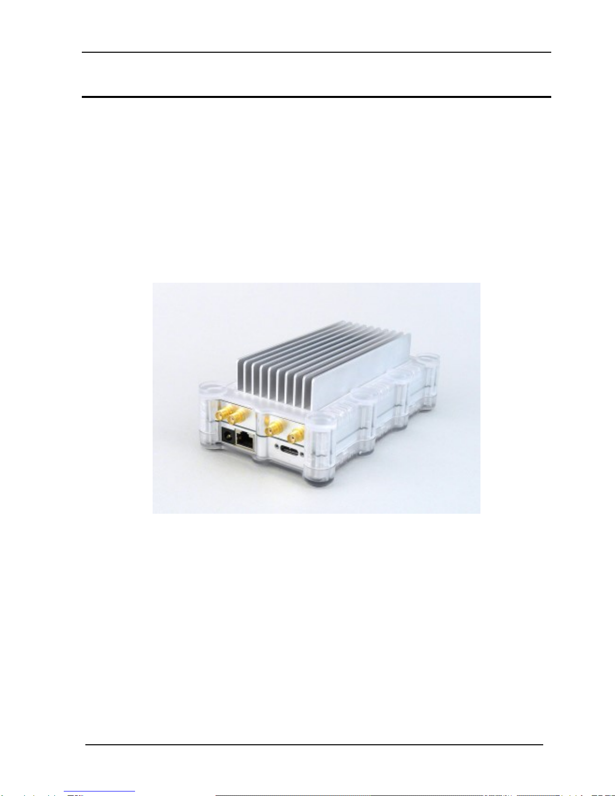
The WiNRADiO WR-G65DDC receiver has been tested and found to comply with the limits for a
Class B digital device, pursuant to Part 15 of the FCC Rules. These limits are designed to provide
reasonable protection against harmful interference in a residential installation. This equipment
generates, uses and can radiate radio frequency energy and, if not installed and used in
accordance with the instructions, may cause harmful interference to radio communications.
However, there is no guarantee that interference will not occur in a particular installation. If this
equipment does cause harmful interference to radio or television reception, which can be
determined by turning the equipment off and on, the user is encouraged to try to correct the
interference by one or more of the following measures:
•Reorient or relocate the receiving antenna
•Increase the separation between the equipment and the receiver
•Connect the computer into a different outlet so that the two devices are on different branch
circuits
•Consult an authorised dealer or an experienced radio/TV technician for help
Caution
To comply with the limits for the Class B digital device, pursuant to Part 15 of the FCC rules, the
WiNRADiO receiver must be attached to a computer certified to comply with the Class B limits.
Only peripherals certified to comply with the Class B limits may be attached to the computer
containing the WiNRADiO receiver. All cables used to connect the computer and peripherals must
be shielded and grounded. Operation with non-certified peripherals may result in interference to
radio and TV reception.
Modifications
Any changes or modifications to the WiNRADiO receiver not expressly approved in this book could
void the user's authority to operate this equipment.
Limitation of Liability and Remedies
The information published in this book has been compiled from several sources. While every
effort has been made to ensure its accuracy, neither the authors nor the publisher can guarantee
that all information is entirely correct or up-to-date. Furthermore, neither the authors nor the
publisher can take any responsibility for the use of this information or any consequences arising
therefrom. WiNRADiO Communications shall have no liability for any damages due to lost profits,
loss of use or anticipated benefits, or other incidental, special or punitive damages arising from the
use of, or the inability to use, the WiNRADiO receiver, whether arising out of contract, negligence,
tort or under any warranty, even if WiNRADiO Communications has been advised of the possibility
of such damages. In no event shall WiNRADiO Communications' liability for damages exceed the
amount paid for this product. WiNRADiO Communications neither assumes nor authorises anyone
to assume for it any other liabilities.
Warning
In certain countries or states it may be illegal to monitor certain frequencies. We cannot accept
any responsibility for the consequences of your non-compliance with government regulations. If
you are in doubt about the regulations in your country or state, please contact your nearest radio
communications regulatory authority.

WiNRADiO G65DDC User’s Guide
4
Table of Contents
Table of Contents.........................................................................................4
Introduction...................................................................................................6
The Hardware................................................................................................7
Installation.....................................................................................................8
Recommended System Requirements.......................................................8
Software and Hardware Installation............................................................9
Setting up the Sound Card .......................................................................10
Connecting the Antenna...........................................................................11
Grounding.................................................................................................11
Getting Started ...........................................................................................13
Achieving Best Selectivity.........................................................................16
Avoiding Front-End Overload ...................................................................17
Inside the Excalibur Sigma........................................................................17
Resizing the Application Window.............................................................21
Drop-Down Menu Controls........................................................................22
Tuning the Excalibur Sigma......................................................................23
Manual Frequency Entry...........................................................................23
Tuning Knob .............................................................................................25
Keyboard Tuning ......................................................................................25
Multiple Receiver Operation .....................................................................26
Point-and-Click Tuning .............................................................................27
Dragging the Passband............................................................................27
IF Shift and Passband Tuning ..................................................................29
Frequency Stepping..................................................................................30
Frequency Display Offset .........................................................................31
Receiver Selection .....................................................................................31
Mode Selection...........................................................................................32
AMS Mode................................................................................................33
ISB and DSB Modes.................................................................................34
DRM Mode................................................................................................35
FSK Mode.................................................................................................38
UDM Mode................................................................................................38
Function Tabs.............................................................................................38
Tuning Tab................................................................................................39
Audio Tab .................................................................................................43
Memory Tab..............................................................................................48
Notch.........................................................................................................54
Squelch.....................................................................................................55
Gain ..........................................................................................................57
Noise Blanker ...........................................................................................60

WiNRADiO G65DDC User’s Guide
5
Pause........................................................................................................61
Spectrum Scopes.......................................................................................63
Zoom Spectrum........................................................................................64
Save and Print Spectrum..........................................................................65
Resolution Bandwidth...............................................................................65
Spectrum Averaging.................................................................................66
Waterfall Spectrum...................................................................................66
Spectrum Markers....................................................................................68
Information Buttons ..................................................................................69
Baseline Level ..........................................................................................70
Peak Hold.................................................................................................70
Audio Spectrum........................................................................................70
Activity Search..........................................................................................72
Recording Functions .................................................................................75
Attenuator...................................................................................................79
Preamplifier.................................................................................................79
RF Filter.......................................................................................................80
S-meter........................................................................................................80
Top Menu Bar .............................................................................................81
File............................................................................................................81
Options .....................................................................................................84
Memory.....................................................................................................98
Scheduler..................................................................................................99
Logger.....................................................................................................103
Plugins....................................................................................................104
Power Switch............................................................................................104
Date and Time Display.............................................................................104
Appendix A – SDR and DDC Primer.......................................................106
Appendix B – Troubleshooting...............................................................113
Appendix C – USB and LAN Interface Diagnostics..............................117
Appendix D – Dealing with Interference ................................................118
Appendix E – Waterfall Spectrum Palettes............................................120
Appendix F – Recording File Formats ...................................................121
Appendix G – G65DDCe Connections ...................................................124
Appendix H – Compliance Declarations................................................125
Appendix I – Safety Disposal..................................................................126

WiNRADiO G65DDC User’s Guide
6
Introduction
Welcome to the WiNRADiO G65DDC receiver, the Excalibur Sigma.
This receiver is an advanced frequency extended successor to the award-
winning WR-G35DDC receiver, the Excalibur Ultra. Like many WiNRADiO
receivers in the past, this advanced software-defined receiver breaks many
new grounds. Some of its features are hard to beat, such as the real-time
88/72 MHz-wide spectrum analyzer, two independent frequency ranges (both
in direct sampling mode) with dedicated inputs, the capability to record up to a
64 MHz wide digitized RF signal, 0.1 ppm frequency stability, USB3 and
Ethernet connectivity (including PoE capability) and much more.
Installed on any modern computer via the USB interface, the Excalibur Sigma
transforms it into a remarkable surveillance, monitoring and testing station
suited for the most demanding applications, and yet still remaining user-
friendly, convenient and remarkably cost-effective.
The WiNRADiO Excalibur Sigma will take you right to the leading edge of what
is possible with today’s technology. As the name Excalibur Sigma suggests, a
magical sword synonymous with power and bravery, this is not just a receiver;
it is a powerful radio communications instrument in a class of its own. We have
crafted it with meticulous workmanship, utmost care, attention to detail and
dedication to excellence, to make it suitable for the most demanding of
applications. We are proud to present you with this instrument and wish you
much success and many hours of enjoyment in putting your WiNRADiO
Excalibur Sigma to a good use.
One of the great benefits and advantages of software-defined radio is its
flexibility and potential for further improvement. By continuously improving the
software, we continue increasing our customers’ return on their investment
long after the receiver purchase. However, this makes producing printed user
manuals impractical, because a printed version may become already obsolete
by the time the manual gets printed and bound. This is why we supply a
complete user’s guide for this receiver in a soft form only. Saving paper is, of
course, yet another side benefit. The user’s guide in a PDF format, will be
installed on your computer as part of the installation process, with a shortcut
placed on the desktop.

WiNRADiO G65DDC User’s Guide
7
The Hardware
The WiNRADiO G65DDC receiver is presented as an external USB-interfaced
design which provides portability and flexibility of use. The WR-G65DDC
hardware is contained in a small metal box, encapsulated with transparent
plastic.
The front of the enclosure contains an indicator LED. The LED also serves for
diagnostic purposes and installation trouble-shooting (see Appendix C – USB
Interface Diagnostics). During normal operation, its flashing can be disabled
by a setting in the application software, should it appear disturbing.
The power input socket requires 12 V DC with a tolerance of ± 1 V. The power
adapter must be rated for a minimum of 1 A.
CAUTION: For best performance and safety, we recommend using only
the power adapter supplied by WiNRADiO, which comes included with
your receiver.
There are two antenna inputsboth being SMA-type connectors with 50 ohm
impedance. The receiver interfaces to a Windows-compatible PC via USB 3.0,
or 1 Gb Ethernet LAN port with PoE (Power over Ethernet functionality
according to IEEE 802.3at).

WiNRADiO G65DDC User’s Guide
8
Installation
The complete WiNRADiO G65DDC receiver package contains the following
items:
•WiNRADiO G65DDC receiver
•Application software, User’s and Installation Guide on a CD ROM
•Installation Guide in printed form
•Warranty information
•AC/DC adapter with power cord
•USB interface cable
In order for the WiNRADiO G65DC receiver to be able to provide best
performance, your computer should fulfil the system requirements specified
below.
Recommended System Requirements
CPU
i5 or better
RAM
4 GB RAM or more
Display
SVGA or better
Hard Disk
separate drive with min. 320 MB/s data
throughput for recording/playback
Sound card
Any standard Windows-supported sound-card
Interface
USB 3.0 port
OS
Windows 7, 8 or 10 (32/64-bit)
The CPU speed directly influences the maximum selectivity and DDC
bandwidth that can be achieved with this receiver. The receiver may still be
usable on slower computers, but with some compromises, for example using
only one of the two receiver channels and/or reduced maximum achievable
selectivity and DDC bandwidth. Other background processes and programs
running simultaneously on the computer may also adversely affect the
receiver’s performance.
Do you have any suggestions about how we could further improve our product, or do
you wish to tell us of your experiences using this receiver in your application? Please
do not hesitate to leave your comments on www.winradio.com/feedback We always
love hearing from you.

WiNRADiO G65DDC User’s Guide
9
Software and Hardware Installation
1. Leave the receiver disconnected from the PC and insert the
installation CD ROM. The installer should start automatically. If the
installation program does not start automatically, choose the Run
command from the Windows Start menu and type D:\INSTALL (if the
CD ROM is the D: drive on your PC).
2. Connect the receiver to the USB port.
3. Connect the supplied power adapter to the power outlet on one side
and the power lead to the receiver on the other side. The blue LED will
flash to indicate that the receiver is ready. Windows should now detect
your new receiver and automatically install the driver.
After all the files have been installed to your hard disk, run the WiNRADiO
G65DDC application by clicking on the new icon that has been installed on
your desktop. Note also a shortcut to the user’s manual file (G65DDC
User’s Guide.pdf) that will also appear on your desktop.
Finally, connect your antenna to the antenna connectors (SMA-type) at the
rear of the receiver. Having a good antenna is most important; see more
details in the chapter Connecting the Antenna.
Something to consider?
WiNRADiO also manufactures numerous antennas
and antenna accessories. For example, the (pictured)
WR-LWA-0130 adapter can be used to match the
impedance of a long wire HF antenna to the 50 ohm
input impedance of a WiNRADiO receiver, as well as
provide a convenient grounding point.
This usually results in a significant signal strength
increase (up to 17 dB in some cases, and approximately 5 dB on average), compared
to a long-wire antenna connected directly to the antenna input of the receiver.
To ensure best performance, we recommend using this long-wire balun for all long-wire
antenna installations.

WiNRADiO G65DDC User’s Guide
10
Setting up the Sound Card
As the digitally down-converted signal from the receiver is transferred to the
PC over the USB interface, no external connection to the PC sound card input
is necessary. The sound card is only used for the demodulated audio output.
On Windows 10, the audio volume can be adjusted using the WR-G65DDC
volume slider inside the Applications section and the master volume inside
the Device section. Both controls need to be unmuted.
Click on the speaker icon and then click on the Mixer link to bring up the
sound card control panel. Different Windows versions may use a different
method of bringing up this control panel; in Windows 10 type mixer into the
Windows Start / Search box to access the "Adjust system volume" link:

WiNRADiO G65DDC User’s Guide
11
To get started, make sure the volume is set approximately as shown above. If
you find that the maximum volume as set on the 'receiver application panel' is
not sufficient, you may then wish to increase the 'sound card' volume later.
Connecting the Antenna
As the old saying goes, “a good antenna is the best amplifier”. No matter how
good a radio receiver is, the performance limit of a radio receiving system is
always determined by the first element of the receiving chain – the antenna.
To make the most out of your WiNRADiO receiver, you should install a good
antenna, preferably located outdoors, as far away as possible from
interference sources. If you are looking for a new antenna, please also check
out the WiNRADiO antenna product range at www.winradio.com/antennas
The specifics of a computer-based receiver may often require careful
consideration with respect to the antenna connection and installation, to make
sure that computer-generated noise does not enter the receiver’s antenna
input.
Grounding
To obtain the maximum possible performance from your receiver, you may
also like to experiment with grounding, in particular when you are using long-
wire antennas. In some cases, signal reception may be significantly enhanced
with improved grounding. Unfortunately, results are not always predictable due
to variations in individual installations, so some trial and error experiments may
be required in the search for ultimate performance.
With long-wire antennas, good grounding is absolutely essential. If you don't
apply any external additional grounding with the receiver, then you are relying
on grounding provided via the power supply or via the computer’s USB
interface. Such grounding may not be optimum as it may introduce noise to the
receiver’s input due to “ground loops”, where the useful signal is sharing the
ground path with undesirable interference.

WiNRADiO G65DDC User’s Guide
12
The grounding requirement does not usually apply with antennas which
do not require ground as a counterpoise to the “live” terminal. For
example, the magnetic field loop antenna, which provides two output
terminals, and also some electric field antennas such as dipole, inverted
"V", etc. These antennas have balanced outputs, and will require
impedance matching to the Excalibur Ultra’s unbalanced 50 ohm input.
A "good" ground for a receiver is one that provides a low impedance path to
ground for radio signals in the frequency range of interest. A metal cold water
pipe located in close proximity to a possible ground connection point could
provide good results. If no such point exists, a copper stake hammered into
the ground may be required. Copper earth stakes can be obtained from
electrical supply outlets.
Assuming a typical installation where the coaxial cable to the receiver enters
the building at some point, an opportunity may exist to make a connection
between the outer shield of the coaxial cable and the suitable ground point. In
order for the grounding to be effective, the connection between the ground
point and the coaxial cable outer should preferably be no more than a few
meters in length. A low impedance connection (such as braid removed from a
section of coaxial cable) should be used to make the connection. In an ideal
situation, the length of coaxial cable to the receiver should be no more than a
few meters in order to provide a low RF ground impedance at the receiver.
In order to make a connection to the coaxial cable, a number of options exist.
These include WiNRADiO antenna accessories such as the WR-CMC-30
Common Mode Choke (see www.winradio.com/cmc30) or the
WR-LWA-0130 Long Wire Adapter (sometimes referred to as a “long wire
balun”; see www.winradio.com/lwa) which, along with their other intended
purpose, the WR-CMC-30 provides a convenient ground connection stud that
will allow the connection to be made.
CAUTION: With any outdoor antennas, be sure to install a lightning
arrestor and disconnect the antenna (and ground it if possible) during
thunderstorms. To prevent receiver damage from static charge build-up,
always ground your antenna momentarily before connecting it to the
receiver.
If it is too difficult to make ground connections near the building, it may still be
well worthwhile experimenting at a point where connections can be more
made more easily. The WR-CMC-30 Common Mode Choke makes it
possible to provide several grounding points along the entire length of the
antenna feedline, in those locations where good quality grounding is available.

WiNRADiO G65DDC User’s Guide
13
Where small physical size is important, magnetic field loop antennas usually
perform best. For indoor applications, WiNRADiO also offers the miniature
AX-17C antenna (see www.winradio.com/ax17c) which does not require
grounding.
Getting Started
The following quick-start introduction is intended to make it possible for you to
enjoy your new receiver as quickly as possible. Detailed operation is described
in the subsequent chapters. We do hope you will return to these chapters as
the WiNRADiO Excalibur Sigma receiver has many unique and innovative
features the usage of which may not be immediately obvious and which would
be a shame to miss.
Start the WiNRADiO Excalibur Sigma receiver application (by double clicking
on the program icon). The receiver’s “virtual control panel” will appear:
The control panel has some basic elements similar to conventional receivers
and many new ones as well. For example, you will note the wideband
spectrum analyzer at the bottom of the application that (if the Spectrum button
is engaged) shows the real-time activity of a wide spectrum, making the
WiNRADiO Excalibur Sigma a true panoramic receiver.

WiNRADiO G65DDC User’s Guide
14
The quickest way to get started with this receiver is to check its operation on
your local stations.
Using the keyboard, type in the frequency of one of your local AM stations: For
example, for 774 kHz, type in 774, then kfor kHz, then press Enter. The
typed-in frequency will appear on the digital frequency display.
When you start the receiver the first time, the AM mode is selected by default.
Otherwise you can set the demodulation mode by clicking on the appropriate
mode selection button at the top-right:
When tuned, you should be able to see the station peak in both real-time
spectrum scopes in the upper section of the application window: The spectrum
scope on the left shows the output of the primary Digital Down-Converter
(DDC1)and the one on the right is that of the secondary DDC (DDC2), which
refines the observed spectrum further.
You can adjust the receiver’s selectivity bandwidth for optimum reception
using the row of numbered buttons at the bottom of the Tuning tab, this being
the left-most tab located just under the AM mode selection button. The
numbers on the buttons represent the bandwidth in kHz.
To adjust the bandwidth continuously, use the DEM BW control located at the
top of the demodulator spectrum scope:
At this point, you should be also able to hear the station. The volume is
adjustable under the Audio tab, located just next to the tuning tab. You can
use either the slider, or select the value next to the Volume edit box, next to
the Mute button.
An alternative and fast way to adjust the volume is by using the left/right arrow
keys of the computer keyboard.

WiNRADiO G65DDC User’s Guide
15
Manual tuning can be done in several ways. Let’s start with the tuning knob:
Place the mouse cursor onto the upper half of the tuning knob, at which point
you will see the cursor change to a curved double ended arrow.
Hold down the right or left mouse buttons to increase or decrease the
frequency, and the knob will rotate clockwise or anti-clockwise, respectively.
If you place your cursor onto the bottom half of the tuning knob, the direction of
the rotation will reverse. (You don’t need to move the cursor up or down to
change the rotation of the knob, simply press either the left or right mouse
button.)
The rotation increment of the tuning knob is 1 kHz. This can be changed easily
using the Alt, Shift or Ctrl keys: If you press the Alt key while tuning, the
increment will decrease ten times (100 Hz). Pressing Shift will decrease the
increment a hundred times (10 Hz). And if you use the Ctrl key, the increment
becomes a thousand times smaller (1 Hz).
Another way of tuning is to use the up and down arrow keys on the PC
keyboard. The Alt, Shift and Ctrl keys can be used to a similar effect as with
the tuning knob, to modify the frequency increment step.
If your mouse has a wheel (as we would recommend), you can also use this;
you might find it somewhat similar to using the tuning knob of a conventional
receiver. And again, the Alt, Shift and Ctrl keys, when used together with the
mouse wheel, modify the tuning step accordingly.
If you press the Shift key while hovering with your mouse cursor over the
individual digits of the main frequency display, the display enters a different
mode where and you can change the digits using the mouse wheel –
presenting another convenient way of quickly tuning to the frequency you
want.

WiNRADiO G65DDC User’s Guide
16
Achieving Best Selectivity
In any software-defined receiver, the maximum achievable selectivity is a
function of the processing power of the host computer: The greater the CPU
power, the “longer” and therefore the sharper its digital filters can be made.
The selectivity of your receiver can be adjusted using the function Filter
length under the top bar menu Options. The greater the Demodulator filter
length parameter, the better the selectivity:
This function also makes it possible to observe the CPU load, which will
depend on this setting. It may not be advisable to select a value resulting in
more than say 30% CPU load as the computer may then become sluggish.
Should the computer become sluggish or even “freeze” as a result of this
adjustment, please reduce the demodulator filter length to a lower value.
Note also that the CPU load can be lowered (while keeping selectivity
high) by reducing the DDC1 and/or DDC2 bandwidths (DDC1 and DDC2
values are shown above the two respective spectrum displays). For
example, HF signals can be demodulated with 20 kHz DDC1 and DDC2
bandwidths without a decrease in the demodulation quality. Wider DDC
bandwidths affect display and recording, while increasing the CPU load
considerably.

WiNRADiO G65DDC User’s Guide
17
Avoiding Front-End Overload
If you are tuned to the HF bands and the S-meter shows the words ADC CLP,
the analog-to-digital converter (ADC) is overloaded (i.e. clipping the signal). In
such a case, use the Attenuator to reduce the level of the signal entering the
ADC. You can use the Auto button which reduces the signal automatically to
the optimum level.
If you experience any installation problems or are unable to tune to any radio
stations at this point, please refer to Appendix B - Troubleshooting.
Should you encounter interference-related problems with your receiver,
effective remedies do exist; please peruse Appendix D – Dealing with
Interference.
Inside the Excalibur Sigma
Let’s have a look at what’s inside this receiver and how it relates to the
graphical user interface of the control application. Here is a simplified
functional block diagram of the hardware portion of the receiver:
The receiver operates in two separate frequency ranges: Range 1 from 1 kHz
to 88 MHz and Range 2 from 118 MHz to 190 MHz.
There are two antenna inputs on the receiver, for each of its respective
frequency ranges. Both antenna inputs are followed by a dedicated signal
chain for its frequency range.
For frequency range 1 the signal chain starts with the antenna input and its
associated protective and impedance matching circuitry, followed by the
Preselector and the Attenuator.

WiNRADiO G65DDC User’s Guide
18
The Preselector contains a bank of user-configurable filters that can be used
to filter out strong frequencies in the vicinity of the received signal, and so
reduce overloading and intermodulation distortion.
The attenuator is adjustable from zero to 21 dB in 3 dB increments and
serves to reduce signal levels in the proximity of strong stations. The
attenuator can be operated either manually, or left to the receiver to determine
its optimum level automatically to avoid overloading.
The signal then passes through a switchable low-noise, low-distortion amplifier
which can be enabled or disabled by the user. When enabled, this adds
approximately 10 dB of amplification, making it possible to achieve higher
sensitivity (at the expense of strong signal handling capability).
Following the amplifier is an anti-aliasing filter, which is necessary for the
digitization.
For frequency range 2 the signal chain starts with the antenna input and its
associated protective and impedance matching circuitry, followed by a 118
MHz high pass anti-alias filter which also effectively suppresses the FM
broadcast band.
The signal then passes through a switchable low-noise, low-distortion amplifier
which can be enabled or disabled by the user. When enabled, this adds
approximately 10 dB of amplification, making it possible to achieve higher
sensitivity (at the expense of strong signal handling capability).
This is followed be the attenuator which is adjustable from zero to 21 dB in 3
dB increments and serves to reduce signal levels in the proximity of strong
stations. The attenuator can be operated either manually, or left to the receiver
to determine its optimum level automatically to avoid overloading.
Following the amplifier is an anti-aliasing low pass filter at 190 MHz which is
necessary for the digitization.
The signals from both frequency ranges meet at signal switch, which selects
the appropriate frequency range according to the tuned frequency. Please
note that only one of the frequency ranges can be used at a time.
The signal is then sampled by a 16-bit analog-to-digital converter (ADC) which
samples the input signal at 210 MSPS (megasamples per second), producing
a steady stream of digital data for the subsequent Digital Down-Converter
(DDC).

WiNRADiO G65DDC User’s Guide
19
The digital data then proceeds via the USB 3.0 or the Gigabit Ethernet
(1000BaseT) to the computer which provides all the additional processing,
filtering, demodulation, signal strength measurement, squelch, noise blanking,
notch, audio filtering and other functions.
Connecting the receiver via the USB 3.0 provides full DDC bandwidth of up to
64 MHz. However when the receiver is connected via a Gigabit Ethernet, the
DDC bandwidth is limited to 16 MHz due to limited throughput of the Gigabit
Ethernet connection.
In the WiNRADiO Excalibur Sigma receiver, the chunk of the input spectra that
is processed by the DDC can be recorded and played back by the PC, making
it possible to “re-receive” signals located anywhere within that chunk. The
maximum width of the DDC chunk (called the DDC bandwidth) is 64 MHz
when connected through the USB 3.0 and 16 MHz when connected through a
Gigabit Ethernet.
The larger the DDC bandwidth, the more CPU processing power is required by
the computer. On slower computers, using the maximum DDC bandwidth may
not be possible as the computer may then become sluggish and the
application may “freeze”.
The chunk of the input signal spectrum seen and processed by the DDC is
shown at the top-left; this is called the DDC1 spectrum. Its bandwidth is
determined by the DDC1 BW control at the top of the DDC spectrum.
Anywhere within the DDC1 spectrum, you can place three independent
demodulators (“virtual receivers”), each of them capable of independently
demodulating signals of different modulation types and different bandwidths.
These signals can also be separately recorded and then played back.
Effectively, the WiNRADiO Excalibur Sigma includes three receivers in one.
You can select any one of these three receivers using the three tabs above the
main frequency display RX1, RX2, RX3). There are some important tuning
ramifications resulting from the fact that all three receivers must reside within
the current DDC spectrum - these will be described in greater detail in a later
chapter, Tuning the Excalibur Sigma.
The spectrum scope at the top-right of the application window shows the
spectrum as seen and acted upon by the currently selected virtual receiver
(DDC2). This spectrum represents the output of the final decimation process
and is available for final filtering and demodulation. As a convenient short-
hand, we will refer to this spectrum simply as the Demodulator spectrum.

WiNRADiO G65DDC User’s Guide
20
As a useful parallel, the demodulator spectrum can be compared to the IF
spectrum of a conventional receiver.
The dark blue rectangular area inside the DDC1 spectrum corresponds to the
demodulator bandwidth, while the gray area inside both the DDC1 and
demodulator spectrums relate to the demodulator filter bandwidth. This
bandwidth represents the selectivity bandwidth of the receiver… and for the
best signal-to-noise ratio of the received signal, you might wish to adjust this
bandwidth to very closely embrace the visible spectrum of the received signal.
You can do this either by using the DEM BW control, or by dragging the edges
of the gray area in the demodulator spectrum.
You can also drag the gray areas sideways, by clicking and dragging at their
center or anywhere inside them, in both the DDC1 and demodulator spectrum.
This is equivalent to the IF Shift function of conventional receivers.
Clicking on any of the three spectrum scopes will cause the receiver to tune to
the corresponding frequency. But as the WiNRADiO Excalibur Sigma consists
of three receivers in one, this does have some ramifications which will be
further explained in the following chapters.
The receiver also features optional external 10 MHz reference input/outputs
and coherence mode of operation, also a 1 PPS pulse input and an FPGA
interface.
Please don’t forget to register as a WiNRADiO user to receive news about new
products, accessories and software upgrades for your Excalibur receiver. Use
our on-line registration form at www.winradio.com/register to take advantage
of this free service.
This manual suits for next models
2
Table of contents
Other RADIXON Receiver manuals