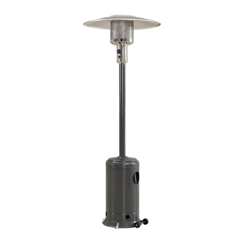
RADtec H1501A User manual

-0-
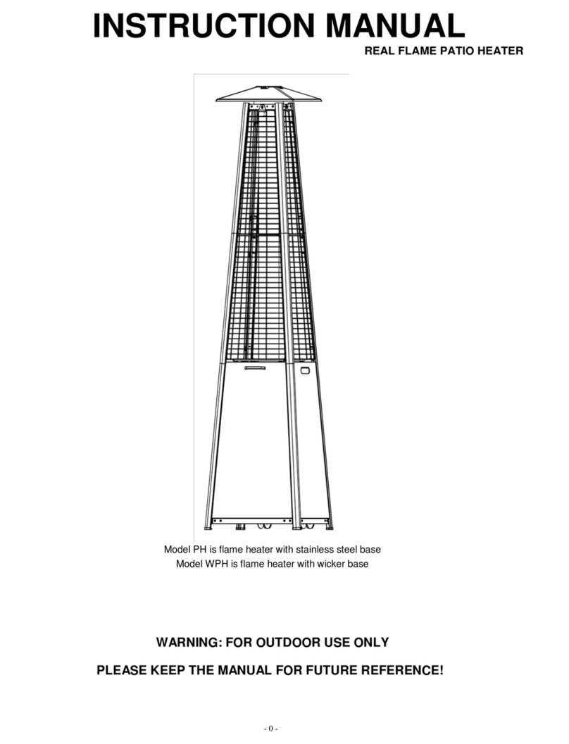
Model PH is flame heater with stainlesssteel base
Model WPH is flame heater with wickerbase
WARNING: FOR OUTDOORUSE ONLY
PLEASE KEEP THE MANUAL FOR FUTURE REFERENCE!
Tower Flame Patio Heater
Intrtion Manal

-1-
TABLE OFCONTENTS
Patio Heater Safety Warnings --------------------------------------------- 1-2
Part List &Hardware--------------------------------------------------------- 3
Exploded View ----------------------------------------------------------------- 4
Patio Heater Assembly ------------------------------------------------------ 4-8
Operating Instructions ------------------------------------------------------- 9
Leak Testing -------------------------------------------------------------------------10
Gas Requirement ------------------------------------------------------------- 10
Connecting To a Gas Cylinder--------------------------------------------- 10
Important Safety Rules ------------------------------------------------------ 11
Maintenance-------------------------------------------------------------------- 11
Servicing------------------------------------------------------------------------- 12
Storage --------------------------------------------------------------------------------12
Troubleshooting --------------------------------------------------------------- 13
Technical Data ----------------------------------------------------------------- 14
Guarantee----------------------------------------------------------------------- 14
Discard--------------------------------------------------------------------------- 14
PATIO HEATER SAFETY WARNINGS
PLEASE READ THE INSTRUCTIONS CAREFULLY EFORE INSTALLATION AND USE
This appliance must be used outdoorsor in a well-ventilated area, andshould not be installed or used indoors.
Change the gas cylinderinawell ventilated area, away from any flammable sources.
The cylinder must be stored outdoors or in a well-ventilated area.
Storage ofthis appliance indoors is permissible only ifthe gas cylinder is disconnectedand removed from the
appliance.
Do not move this appliancewhen in operation, and wait until the unit has cooled beforemoving.
Do not attempttoalter the appliance in any manner.Donot paint the radiant screen,control panel or reflector.
Donot obstruct the ventilation holes ofthe cylinder housing.
The appliance must be installed and gas cylinder storedinaccordance with local gas fitting regulations.
Turn offthevalve at the gas cylinderor regulator before moving the appliance.
Repairs should be done by a qualified repairman.
In case of violent wind, particular attention must be taken against tilting of the appliance.
Check that the regulator sealiscorrectly fittedandable to fulfilitsfunction.
Close the gassupply at the valve of the gas cylinderor the regulator after use.
Donotusethis appliance until all connections havebeen leaktested.
In the event of gas leakage, the applianceshould not be used or if lit, the gassupply should be shut off,andthe
appliance shouldbeinvestigatedand corrected before itis used again.

-2-
•
Check the tubing or the flexible hose per month and eachtime the cylinderischanged.
•
The tubing or the flexible hose must be changed within the prescribedintervals or within one year.
•
Thehose assembly must be replaced priortothe appliancebeing putintooperation ifthere is evidenceof
excessiveabrasion or wear, or ifthehose is damaged. A specified replacement hose assembly shall be
used.
•
Theheater should be inspected before use andat least annually by aqualified service person. More frequent
cleaningmaybe required as necessary. Itis imperativethat thecontrol compartment, burners and circulating
air passageways ofthe appliance be kept clean.
•
Shut off and check heater immediately if any of the followingconditions exist:
D The smell of gasinconjunction with extreme yellow tipping of the burner flames.
DHeater does not reach a proper temperature. A temperature less than 40 degrees Fahrenheit will cause
restricted heatflow and theappliance will notworkproperly.
D The appliance starts makingpopping noises duringuse (aslight poppingnoise is normal when
the appliance is extinguished).
•
The regulator & hose assembly must be located out of pathways where people may trip over it, or in an area
where the hose willnot be subject to accidental damage.
•
Any guard or other protectivedeviceremoved for servicing the heatermust be replaced before operating the
heater.
•
Children and adults should be warnedofthe hazards of high surfacetemperatures and should stay away to
avoid burns or clothing ignition.
•
Young children and petsshould be carefully supervisedwhen they areinthe areaof the heater.
•
Clothingor other flammable materials should not be hungfrom theapplianceorplaced onornear the
appliance.
•
Donot placearticles on oragainst this appliance.Certain material or items when storedunderor near this
appliance will be subjected to radiant heat and couldbeseriouslydamaged.
•
Donot use or store flammable materials near this appliance.
•
Do not spray aerosols in thevicinity of this appliance while it is in operation.
•
Always maintain at least 36 in clearancefromcombustible materials.
•
Always position the appliance on a firm levelsurface. An amply ventilated area must have a minimum of 25% of
the surface area open. The surfacearea is the sum of the walls surface.

-3-
PATIO HEATER PART LIST
PART # PART NAME PICTRE TY
A
REFLECTOR
1
FLAMESCREEN
1
C
MESH GARD - PPER
4
D
MESH GARD - LOWER
4
E
SPPORTAR - PPER
4
F
SPPORTAR - LOWER
4
G
GLASS TE
2
H
CONNECTOR
Glass Tube Connector
1
I
RERRING
1
RNER ASSEMLY
TAN HOSING ASSEMLY
1
L
CHAIN (ASSEMLED WITHDOOR)
1
HARDWARE
PART # PART NAME PICTRE TY DESCRIPTION
AA M5 CAP NT
4
TOCONNECT REFLECTOR AND
FLAMESCREEN
STANDARD
SCREWS &WASHER 12
M5 8 SCREW & M5 WASHER
TO FIRNERASSEMLY ON
THE TAN HOSING ASSEMLY.

-4-
EPLODED IEW

-5-
PATIO HEATER ASSEMLY
ASSEMLY INSTRUCTIONS
•
List of Required Tools: Philips Screwdriver
•
LeakDetection Solution one partdetergent and threeparts water
•
Aemle all nt an olt looel at irt Titen all onnetion ater omletion o aeml
Tieaeor wor an inreae te tailit o te aliane
•
efore assembly, make sure all packing material and any transmit protection must be removed.
•
Small deviations in equipment may occur.
•
If any partis missing or damaged,do not attempt to assemble this product, Contact customer service for
replacement parts.
•
Assembly should be performed on a flat, level, non-abrasive surface.
•
ESTIMATEDASSEMLY TIME: 45 minutes.
STEP : Laydowntank housingassembly () as
shownabove. Takeoff the door and take out all parts.
STEP : eep theburner with the igniter side up. Fix
the burner assembly () totank housing using 4pcs M5
Screws and Washers ().
STEP : nscrew2pcs M5 screws and washers ()preassembled in Support ar Lower (F).
Insertupper Support ar (E)tolower Support ar (F) and fix the connection using 2pcs screws and washers
().Repeat this step and connect other3sets of support bars.

-6-
Repeat this step and connect Flame Screen () to other 3 sets of upper Support ars. (See Figure Ⅲ,Ⅳ)
STEP : Place Reflector (A) on the Flame Screen ()
and fix the connection using 4 M5 CAP NTS (AA).
STEP : nscrew8M5Screws and Washers () preassembled on topof tank housing assembly ().
Place the lower Support ars to the top ofthe tank housingassembly.Make sure to match the top ends of
the tank housing assembly with the slot ofthe lower Support ar.Match the threaded hole and fix each
connection with2M5Screws and Washers ()

--
STEP : Insert4projecting ends of each lower Mesh Guard (D) into the seatslots of lower the Support ar
(F) asshown in picture. Fix all lower Mesh Guards (D) except the front side.
Guard Fastening Plate
STEP : nscrew 4 Guard Fastening Plates
preassembled with the sides of FLAMESCREEN
().
STEP : Fix all upper Mesh Guards to the upper Support ar (E) except the front side.

--
a
-
-
-
1
--
--
-
-
-
-
<--
STEP :PutRubber Ring (I) around the burner hole. Connect the 2 GlassTubes (G) with Connector (H) .Hold
the whole glass tubeassemblycarefully.Insert the top end into the bottom holeof the Flame Screen as much as
possible. eep the wholeglass tube assembly vertical andsit it on the Rubber Ring (1).
NOTE: GLASSTUES ARE FRAGILE HANDLE WITH GLASS TUESCAREFULLY ANDSLOWLY!

--
OPERATING INSTRUCTIONS
EFORE FIRST USE AND AFTEREERY GAS CYLINDERCHANGE THE GAS DELIERY SYSTEMMUST
EPURGED OF AIR EFOREIGNITING! TODOTHIS TURN THE CONTROLKNO COUNTERCLOCKWISE
TO THE PILOT SETTING PRESS KNO IN AND HOLD FOR MINUTES EFORE ATTEMPTING IGNITION
ATTERY REPLACMENT
Remove impulse ignition cap from urner Assembly () by turning cap counterclockwise.Install 1 AAA battery.
Negative end ofbattery goesinfirst, then replace impulse ignition capby turning cap clockwise.
TO LIGHTTHE PILOT
•
Check all connections prior toeach use.
•
Turn on main gas supply at source.
•
Press to turn control knob counter-clockwise to
PILOT, seephoto on the right.
•
Push the control knob in, while simultaneously
pressing the IGNITION button repeatedly until the
pilot flame is lit. Continue to depress the control
knob for at least 10 seconds to assure the pilot
remains lit after releasing the knob.
•
If the pilot fails to ignite, press the knob clockwise
to OFF and repeat.
TO LIGHTTHE PATIOHEATER
•
The pilot should be lit and the knob settoPILOT.
•
Hold the knob in gently and turn counter-clockwisetoLOW.
•
After the glass has warmed up 1-5 minutes, turn knob clockwise fromLow to HIGH as needed.
Note:The burner may be noisy wheninitially turned on. To eliminate excessive noise from the burner turn
the controlnob to the ilot osition. Then turn the nob to the level of heat desired.
RELIGHTING
•
Turn Control nob to OFF.
•
Wait at least 5 minutes, to let gas dissipate, before attemptingtore-light pilot.
•
Repeat the Lighting steps.
TO ETINGUISH
•
Hold the knob in and turn the knob clockwiseto OFF
•
Close the valve of the gas cylinder or the regulatorafter use.
•
Close the gasbottle andallow the appliancetocool before moving.
Note: After use some discoloration of the emitter screen is normal. Close reulator after use allow the
aliancetocool before movin.

-10-
LEAK TESTING
NEER USE A NAKED FLAME TOCHECK FOR LEAKS
NEER LEAK TEST WHILESMOKING
The gas connections on this appliance are leaktested atthefactory priorto
shipment.
This applianceneeds tobeperiodically checkedfor leaks. and an
immediate check isrequired ifthe smell of gas is detected.
•
Makeasoap solution using 1 partliquid dish-washing soapto3parts
water. The soap solution can be appliedwith asoap bottle, brush, or rag
to the leaktestedpoints shown in the figure above.
•
The valve of the gas cylindershould be in the OFF position at this point of
the leaktest. Once the soapysolution is applied to the gas connections,
the valve of the gas cylinder needs to be turnedtothe ON position.
•
Soap bubbles will begin to form in the soapy solution if a leakispresent.
•
In case of a leak, turn offthe gas supply. Tighten any leaking fittings, then
turn the gas supply on and recheck.
GASREUIREMENTS
•
The appliance must use an EN12864 or EN16129 approved gas regulator and CE approvedgas hose with a
length of 20in (S3212 and EN163-1).Choosetheproper regulatoraccording to outlet pressure in the
technical table in page14.
You will need topurchase a suitable gas hose and regulator from your local gas dealer, Iftheappliancedoes
notinclude agas hose andregulator.
•
Neveruse agas cylinder withadamagedbody, valve,collar, or foot ring. A dented or rusty gas tank maybe
hazardous and should be checked out by agas supplier.
•
Never connect this appliance to an unregulated gas source.
•
When the appliance is notinuse, turn the gas cylinder OFF.
•
Always performaleaktest on gas connections wheneveracylinderisconnected.If bubbles forminthe leak test
solution, do not use.Never use a flametotest for leaks.
CONNECTING TO A GAS CYLINDER
•
It is recommended you use a max. 33lb or smaller gas cylinder (maximum height 25in) refertoyour gas
supplier for suitablegas cylinder.
•
An approved gas regulatorisused according to appliance categories and countrieslisted in data plate. An
approved flexible hose would be changed when the national conditions requireit.
•
Assembly of the tubing must be conducted by a qualified personnelindestination countries.
•
Only changegas cylinders outdoorsor in a well-ventilated area away from naked flames and any other source of
ignition (candle, cigarettes, other flame producingappliances.).
•
The gas cylindermust always be used in an upright position.
•
Close the heater control knob by turning fully clockwise.
•
Close the gas cylindertap and then attach the regulator onto the gas cylinder.
•
Tighten all connections firmly and with a spanner where appropriate. The cylindershould be located on the
cylinder base.
•
Ce orlea at all oint in oa water I a leaion titen te oint an ten retet

-11-
IMPORTANTSAFETY RULES
For use outdoors or in amplyventilated areas.
An amply ventilated area must have a minimum of 25% of the surface area open.
The surfaceareais the sum ofthe walls surface.
Theuseofthis appliance in enclosed areas can bedangerous and is
PROHIITED.
Children and adultsshould be aware of the high operating temperaturesof areas
above the postwhen operating this heater. Children should be carefully
supervised when in the vicinity of the heater.
NEERhang anything,including clothes or any other flammable items, on this
heater.
DO NOT operate this heater unless it is fully assembled with its reflector in place.
Respect theminimum clearances fromcombustible materials.
MAINTENANCE
To enjoy years of outstanding performance fromyour heater, make sure you perform the following maintenance
activities on a regular basis:
•
eep exterior surfaces clean.
•
se warm soapy water for cleaning.Never use flammable or corrosive cleaning agents.
•
While washing your unit, be sureto keep the area around the burner and pilot assembly dry at all times. If the
gas controlisexposedtowaterinany way, O NOT trytouse it. It must be replaced.
•
Airflow must be unobstructed. eep controls, burner and circulation air passageways clean. Signs of possible
blockageinclude:
•
Gas odor with extremeyellow tippingof flame.
•
Heater does NOTreach the desired temperature.
•
Heater glow is excessively uneven.
•
Heater makes popping noises.
•
Spiders andinsects can nestinburner or orifices. This dangerouscondition can damage the heater and render
it unsafe for use. Clean burner holes by usingaheavy duty pipe cleaner. Compressed air may help clear away
smaller particles.
•
Carbon deposits may create a fire hazard. If any carbon deposits develop,clean dome and burner with warm
soapy water.
Note:ina saltair environment such as near the sea corrosion occurs more uicly than normal.
Freuently chec the corrodedareas and reairthem romtly.

-12-
SECN
•
Please consultyour local dealer for servicing this appliance andreplacement of its parts. The servicingofthe
appliance shouldbecarried out only by authorized personnel.
•
Caution: do not useunauthorized parts or components for this appliance, only use original equipment
replacement parts andcomponents. Theuseof unauthorized parts or components will voidthe warranty and
can create an unsafecondition.
STORAGE
Tere i no limitation on te toraeo te aliane inoor roie tat te lineriremoe rom te
aliane
Between uses:
•
Turn control knob OFF
•
Turn gas cylinderOFF
Store heater upright in an areasheltered from direct contact with inclement weather (such as rain,sleet, hail,snow,
dust and debris).
If desired,covertoprotect exterior surfaces and to prevent buildupin air passages.
Note: ait until heater is cool beforecoverin.
urin eriods ofextended inactivity or when transortin:
•
Turn control knob OFF.
•
Disconnect gas cylinder and move to a secure, well ventilated location outdoors. DO NOT storein alocation that
will exceed 50C.
Store heater upright in an areasheltered from direct contact with inclement weather (such as rain,sleet, hail,snow,
dust and debris).
If desired,cover heater toprotect exterior surfaces and toprevent buildupin air passages.
Note: ait until heater is cool beforecoverin

-13-
TROULESHOOTING
IFTHEPROLEM IS: AND THIS CONDITIONEISTS: THENDOTHIS:
Pilot wont lit
Cylinder valve is closed Open valve
lockage in orificeorpilot tube Cleanorreplace orificeorpilottube
Air in the gasline
Open gasline and bleed it (pressing
control knob in)for not more than
1-2 minutes oruntil you smell gas
Low gas pressure Replacegas cylinder
Igniter fails se match to light pilot, and obtain new
igniter and replace.
Pilot wonttalit
Dirt build up around pilot Clean dirt fromaround pilot
Connection betweengas valve and pilot
assembly is loose
Tightenconnection and perform
leaktest
ad thermocouple Replace thermocouple
rner wontlit
Gaspressure is low Replacegas cylinder
lockage in orifice Clear blockage
Control knob is notin ON position Turn control knob toON position
rner lameilow
Note:Donot operate
heater below
5℃(F
Gaspressure is low Replacegas cylinder
Outdoortemperature is greater than 5℃(40F)
and tank is less than25% full
Replacegas cylinder
Supply hose is bent or kinked Straighten hose and perform leak test on
hose
Control knob is fully ON
Turn control knob toOFF, let itcool to
roomtemperature and check burner and
orifices for blockage
Emitter low
neen
Note: otto 5 o
etter norall oe
not norall low
Gaspressureis low Replacegas cylinder
ase is not onalevel surface Placeheater on a level surface
Heater not level Level heater
Caron il Dirt or filmonreflectorandemitter Cleanreflector and emitter
Ti la moe lockage in burner
Turn control knob toOFF, let itcool to
roomtemperature and remove
blockage and clean burner inside and
outside.

- 14-
TECHNICAL DATA
Model:H1501A&H1502A&H1505&H1507&H1510
Heatinput ∑Qn(Hs)=11.2kW
Consumption: 815g/h
PIN: 0063CL7070 0063
CountryCode
CH-ES-FR-GB-
GR- IE-IT-PT
BE-CY-CZ-DK-EE-FI-
GR-IT-LT-LV-MT-NL-NO-
SE-SI-SK-BG-RO-TR
AT-CH-DE PL CZ-FR-GB
-GR-IE-PT
AT-CH-
DE-NL
Gas Category I3+(28-30/37) I3B/P(30) I3B/P(50) I3B/P(37)I3P(37) I3P(50)
Type of Gas Butane Propane Butane/
Propane/Mixture
Butane/
Propane/
Mixture
Butane/
Propane
/ Mixture
Propane Propane
Gas pressure 28-30
mbar 37mbar 30mbar 50mbar 37mbar37mbar 50mbar
InjectorMarking 1.6 1.6 1.4 1.5 1.6 1.5
Warnn
Read theinstructions before using this appliance.
The appliance must beinstalled in accordance ith instructions and local regulations.
The use of this applianceinenclosed areas can be dangerous and is PROHIBITED.
For use outdoors orinamply entilated areas.
An amply entilated area must hae a minimum of 25 of thesurface areaopen.
The surface area is thesum of the alls surface.
L Warran
RADtecproides a 30-Day Return Windo (see refund and return policy page) and the folloinglimited
arranty. This limited arranty extends only to the original purchaser.
Please note that any arranty serices or uestions must be accompanied by ordernumber from the transaction
through hich the arranted product as purchased and the ID number locatedon the unit. The order number
and ID sere as your arranty numbers and must be retained. RADtecill offer no arranty serice ithout
these numbers. RADtec arrants this product and its parts against defectsin materials or orkmanship for (1)
year parts and labor (residential use) and (1) year parts andlabor (commercial use) from the original ship
date. During this period RADtec ill repair or replace defectie parts ith ne or reconditioned partsat
RADtecs option ithout charge to you.
Shipping fees incurred fromreturns for under-arrantyserice in the first 30-days ill be paid by RADtec. All
shipping feesboth to and from RADtec folloing this 30-day period must be paid by the customer. All returns
both during and folloing the 30-day period must be affectediathe Procedures for Obtaining Warranty
Serice described belo. All original parts (parts installed by RADtecat theoriginal build) replaced by RADtec
orits authoried serice centerbecome the property of RADtec. Any after-market additions or modifications
ill not be arranted. The heater onerisresponsible for the payment at current rates for any serice or repair
outside thescope of this limited arranty.
RADtec makes no other arranty either express of implied including but not limited toimplied arranties or
merchantability fitness foraparticularpurpose or conformity to any representation or descriptionith respecttothis
heater other than asset forth belo.RADtec makes no arranty or representation either express or implied ith
respect to any other manufacturers product or documentation its uality performance merchantability fitness fora
particular purpose or conformity to any representation or description.

This manual suits for next models
4
Table of contents
Other RADtec Patio Heater manuals