Detroit Radiant Products GPH Series User manual

This heater
must
be installed and serviced by a Gas Safe Registered Gas Engineer
only! Conversion of the heater for use with other gases must be carried out by a Gas
Safe Registered Gas Engineer. Read these instructions carefully before attempting to
install, operate or service the heater.
This heater is not approved for use in indoor residential applications and must
never be install indoor in the home. This heater may only be used in outdoor residential
applications or indoor/outdoor commercial (or industrial) applications. Installation in
residential indoor spaces may result in property damage, asphyxiation, serious injury
or death.
Failure to comply with these warnings and instructions, and those on the heater, could
result in personal injury or death.
WARNING
!
For Use in the UK (GB) and Ireland (IE) Only. These instructions are only valid if the country code
appears on the appliance. If the code does not appear on the appliance, refer to the technical instructions
for adapting the appliance to the conditions for use in that country.
0086
© 2011 Detroit Radiant Products Co.
LIOGPH-Rev. 23411
Print: 2M-9/10-r1_8/22/11(DRP)
Replaces: LIOGPH-1m-5/08(DRP)
WARNING
!
Keep these instructions for future reference.
For Your Safety
If you smell gas:
• Shut off gas to the appliance. • Call your gas supplier. Do not use any phone in your building.
• Extinguish any open flame. • Follow the gas supplier’s instructions.
• Do not try to light any appliance. • If you cannot reach your gas supplier, call the fire department.
• Do not touch any electrical switch.
GPH Series Manual
Gas-Fired High Intensity Patio Heater
Installation, Operation,
Maintenance and Parts
NOTICE

Contents
1.0 Safety . . . . . . . . . . . . . . . . . . . . . . . . . . . . . . . . . . . . . . . . . . . . . . . . . . . . . . . . . . . . . . . . . . . 3
Applications.......................................................... 3
Safety Signs and Labels ................................................ 4
Regulations and General Specifications. . . . . . . . . . . . . . . . . . . . . . . . . . . . . . . . . . . . 5
Design.............................................................. 6
2.0 Installation . . . . . . . . . . . . . . . . . . . . . . . . . . . . . . . . . . . . . . . . . . . . . . . . . . . . . . . . . . . . . . . 7
Mounting the Heater . . . . . . . . . . . . . . . . . . . . . . . . . . . . . . . . . . . . . . . . . . . . . . . . . . . 7
Clearance to Combustibles..............................................10
Gas Supply . . . . . . . . . . . . . . . . . . . . . . . . . . . . . . . . . . . . . . . . . . . . . . . . . . . . . . . . . . 11
Electrical Requirements . . . . . . . . . . . . . . . . . . . . . . . . . . . . . . . . . . . . . . . . . . . . . . . . 13
Ventilation . . . . . . . . . . . . . . . . . . . . . . . . . . . . . . . . . . . . . . . . . . . . . . . . . . . . . . . . . . . 14
3.0 Operation ................................................................15
Pre-Commissioning....................................................15
Commissioning . . . . . . . . . . . . . . . . . . . . . . . . . . . . . . . . . . . . . . . . . . . . . . . . . . . . . . . 16
Sequence of Operation.................................................17
Heater Control Wiring ..................................................17
4.0 Maintenance..............................................................18
Periodic Maintenance . . . . . . . . . . . . . . . . . . . . . . . . . . . . . . . . . . . . . . . . . . . . . . . . . . 18
Troubleshooting . . . . . . . . . . . . . . . . . . . . . . . . . . . . . . . . . . . . . . . . . . . . . . . . . . . . . . 19
Replacement Procedures . . . . . . . . . . . . . . . . . . . . . . . . . . . . . . . . . . . . . . . . . . . . . . . 19
Converting Gas Type...................................................21
5.0 Parts ....................................................................23
Heater Component Breakdown...........................................23
Heater Component Parts List ............................................24
2
WARNING
!
WARNING
!
Improper installation, adjustment, alteration, service or maintenance can cause
property damage, serious injury or death. Read and understand, the installation,
operating and maintenance instructions thoroughly before installing or servicing this
equipment. Only Gas Safe Registered Gas Engineers and service personnel may
install or service this equipment.
3
1.0 Safety • Applications
Applications
This heater is certified for use in both commercial and outdoor domestic installations. Ventilation
requirements vary according to the type of installation.
Commercial Installations
The heater may be installed indoors in commercial buildings subject to the ventilation requirements of the
space to be heated. Refer to page 14.
Infrared heaters are designed and certified for use in industrial and commercial buildings such as outdoor
restaurant patios, warehouses, manufacturing plants, aircraft hangars and vehicle maintenance shops.
For maximum safety, the building must be evaluated for potential hazards before installing the heater
system. A critical safety factor to consider before installation is the clearance to combustibles.
Outdoor Domestic (Residential) Installations
This heater is NOT suitable for use in any indoor residential situation. It may be installed outdoors subject
to the following conditions:
The heater must be installed in accordance with the requirements of EN 14543:2005 and other relevant
standards. The heater must be protected against direct rainfall by a roof, canopy or other means. Ensure
that clearances to combustibles (See Table 2.2, page 10) are maintained at all times and that the area is
amply ventilated. Refer to page 14.
Not For Indoor Residential Use. Installation of an infrared heater system in
residential indoor spaces may result in property damage, asphyxiation,
serious injury or death. In residential applications, this heater may only be
used outdoors.
1.0 Safety
WARNING
!
Storage of petrol or other flammable vapors or liquids in the vicinity of this or any other
appliance may result in fire or explosion.

1.0 Safety • Safety Signs and Labels
4
!
CLEARANCE TO COMBUSTIBLES
FIRE HAZARD. Always maintain published clearance to combustibles.
In locations used for the storage of combustible materials, signs must be
posted. Consult manual for additional guidelines.
MODEL NO.
DANGER
SIDE(S) BELOW TOP BEHINDEND(S) FRONT
ALL MODELS
(in millimeters)
MOUNTING
ANGLE
0°
0°
30°
30°
22”
559mm
22”
559mm
14”
356mm
N/A
N/A
46”
1168mm
46”
1168mm
13”
330mm
17”
432mm
N/A
N/A
8”
203mm
N/A
N/A
46”
1168mm
ALL MODELS
(in inches)
Contact may cause burn.
Do NOT touch hot surface.
Allow to cool before
servicing.
This heater must be installed
by qualified personnel only
and in accordance with the
latest edition of the
ANSI/NFPA Standards.
(ANSI/NFPA 88A Parking Structures), 88B
(Repair Garages), 409 (Aircraft Hangars).
Observe all country, state and local codes.
LIGHTING INSTRUCTIONS
1. Rotate heater’s valve knob to “ON” position.
2. Close electrical circuit (usually thermostat).
3. If the heater fails to light, turn “OFF” gas, open electrical circuit and wait 5 minutes
before repeating.
Avoid Serious Injury or
Death. Improper installation,
adjustment, alteration, service
or maintenance can cause
property damage, injury or
death. Read the installation, operation and
maintenance manual thoroughly before
installing or servicing this equipment.
This is not an explosion-proof heater. Where
there is the possibility of flammable vapors or
dusts, consult the local fire marshal, fire
insurance carrier or other authorities for
approval of the proposed installation. Always
maintain minimum ventilation requirements.
30°
This side down
END VIEWSIDE VIEW 0° Mounting END VIEW
30° Mounting
The minimum end clearance is 22” or 559mm.
F/N: LLDR009 - Observe Proper Gas Type (Natural Gas)
F/N: LLDR010 - Observe Proper Gas Type (LP Gas)
Safety Signs and Labels
It is important to provide warnings to alert individuals to potential hazards and safety actions. It is
important to post a sign “specifying the maximum permissible stacking height to maintain the required
clearances from the heater to the combustibles” near the heaters thermostat or in absence of such
thermostats in a conspicuous location.
Safety warning labels must be maintained on the infrared heater. Illustrations of the safety labels, and their
locations, are pictured below. In locations used for the storage of combustible materials, signs must be
posted to specify the maximum permissible stacking height to maintain the required clearances from the
heater to combustibles. Signs must either be posted adjacent to the heater thermostats or in the absence
of such thermostats in a prominent location.
Top Panel
F/N: LLPCL003
230V Patio Heater
Clearance to Combustibles Label
WARNING OBSERVE
PROPER GAS
DO NOT
ROTATE CONTROL
ASSEMBLY FOR
GAS TYPE
ONLY
USE TWO
WRENCHES
TO TIGHTEN

5
1.0 Safety • Regulations • General Specifications
Regulations
Notwithstanding their limited scope, this appliance must be installed in accordance with the relevant
provisions of the following regulations:
UNITED KINGDOM
Gas Safety (Installation and Use) Regulations 1984 and BS 6896:2005. Due account should be taken of
any obligations arising from the Health and Safety at Work etc Act 1974, the current Building Regulations,
the current I.E.E. Regulations and other relevant codes of practice.
IRELAND
I.S. 3212:1987, ICP 4, I.S. 327. Due account should be taken of any obligations arising from the current
Building Regulations, the current I.E.E. Regulations and other relevant codes of practice.
General Specifications
Figure 1.1 • Main Dimensions
END VIEW
216 mm
229 mm
SIDE VIEW
1074 mm
Model No. Nominal
Input Weight
(kg) Nox
Class Electrical Supply
Voltage Current Frequency Max. Power
GPH 9 9 kW 26 Class 4 230V 0.15A 50Hz. 38W
GPH 10 10 kW 26 Class 4 230V 0.15A 50Hz. 38W
Table 1.1 • Specifications

6
1.0 Safety • Design
To ensure a safe, properly designed heating system, a layout should be developed for the correct
placement of the infrared heater(s). Aside from safety factors such as clearance to combustibles
(see Table 2.2 on page 10), you should take into consideration:
• The environment (e.g., is it cold/drafty, average, protected)?
NOTE: The effective infrared surface temperature of a person or object may be diminished
with wind above 10 kph, wind barriers may be required.
• What is the area of heat coverage needed?
• Is the heater being used in a social gathering area, or work station(s)?
• The mounting height of the heater (see Table 2.1, Figure 2.1, page 8).
• The type of mounting to be used.
• Gas supply and connections.
• Combustion, ventilating air supply and exhaust path.
• Electricity and wiring to the heater.
This installation manual along with local codes and regulations address these issues. It is critical that you
read, understand and follow all guidelines and instructions. Always inspect and evaluate the mounting
conditions, space for exhaust, gas supply and wiring.
Design
IMPORTANT: Fire sprinkler heads must be located at an appropriate distance from the heater. This
distance may exceed the published clearance to combustibles. Certain applications will require the use of
high temperature sprinkler heads or relocation of the heaters.
Sprinkler systems containing propylene glycol or other flammable substances are not to be used in
conjunction with this heater without careful consideration for and avoidance of potential fire or explosion
hazards.

7
2.0 Installation • Mounting the Heater
2.0 Installation
WARNING
!
Read and understand, the installation, operating and maintenance instructions
thoroughly before installing or servicing this equipment.
Only Gas Safe Registered Gas Engineers and service personnel may install or service
this equipment.
To ensure your safety, and comply with the terms of the warranty, all units must be installed in accordance
with these instructions.
WARNING
!
Mounting the Heater
Improper suspension of the infrared heater may result in collapse and persons being
crushed. Always suspend from a permanent part of the building structure that can
support the total force and weight of the heater.
Failure to maintain minimum clearance to combustibles may result in fire and/or explosion,
property damage, serious injury or death. Always maintain minimum clearances and post
signs where needed. Signs should state the hazards for the particular application and be
legible for the building occupants. Consult the factory or a factory representative for
additional information on signage compliance.
The heater can be suspended with chains or rigid threaded rod. Regulations, codes, or conditions such
as wind drafts or other variables can cause movement of the heater and may require rigid threaded rod.
Avoid excessive movement and/or vibration of the gas connection by rigidly mounting the heater (see
Figure 2.3). Optional mounting brackets (P/N: PH-BKT) can be used in place of rigid threaded rods.
Consult all applicable codes and regulations before installation.
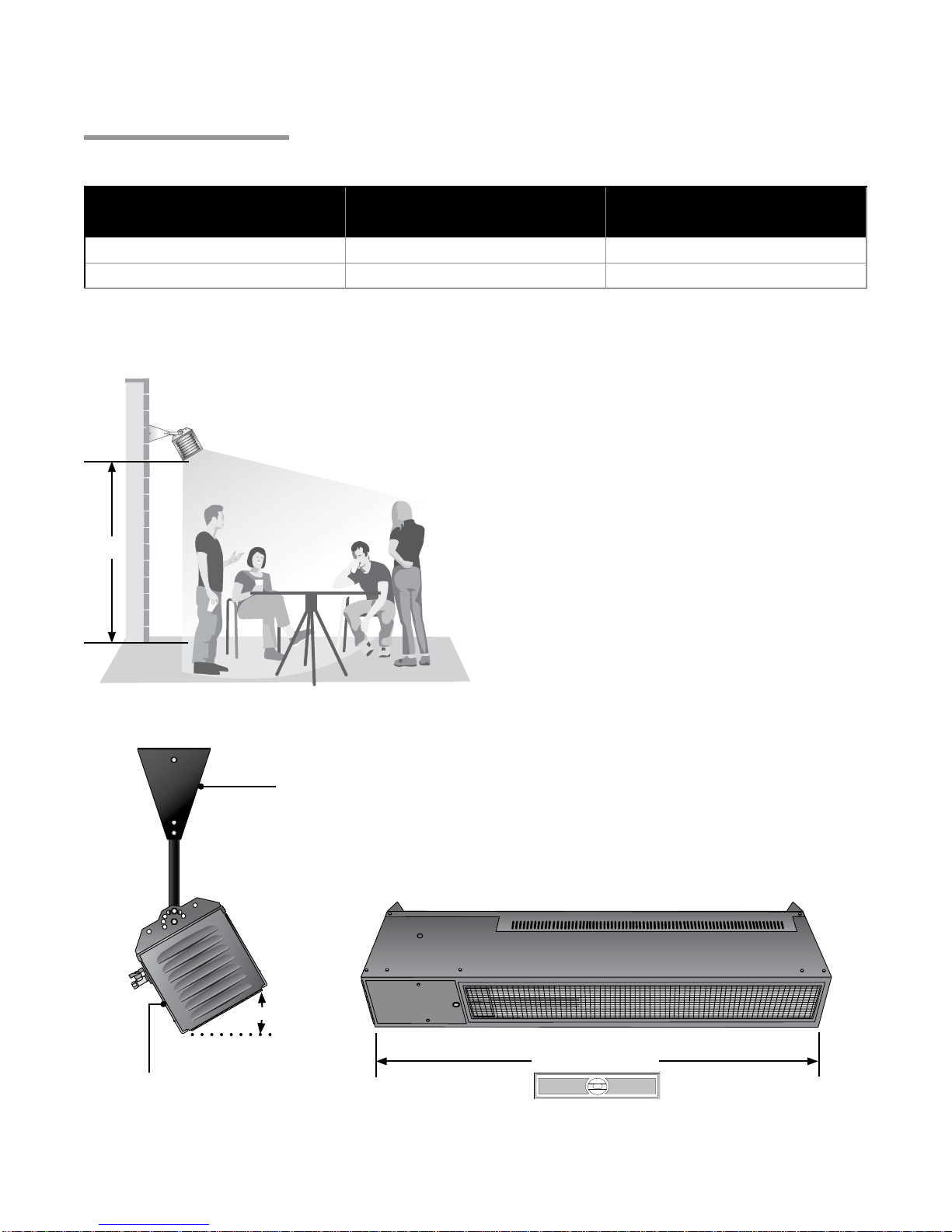
The heater must be level from end to end and can be set at an angle between 0° and 30° from horizontal.
The gas connection and power cord must be located on the lower side (see Figure 2.2).
Whenever possible, fit the heater at the recommended fixing height above floor level (Table 2.1).
When considering heater position, ensure that the required minimum clearances between the various
heater surfaces and combustible material are preserved (Table 2.2).
WARNING
!
Conditions such as wind drafts or other variables can cause movement of the heater and
may require it to be rigidly mounted. Avoid excessive movement and/or vibration of the
gas connection by rigidly mounting the heater.
8
Table 2.1 • Recommended Mounting Heights
Model & Input Recommended Fixing Height
(Dim. A) Approximate
Area Covered
GPH 9 (9 kW) 2000 to 2700 mm 6.0 m2
GPH 10 (10 kW) 2000 to 3100 mm 7.5 m2
A
Figure 2.1 • Recommended Mounting Heights
NOTE: This table is provided as a guideline. Actual conditions dictate variances from this data.
Level end to end
Optional mounting
bracket (P/N: PH-BKT)
30° End
Figure 2.2 • Heater Orientation
End
Mounting the Heater
The heater must be level end to end and mounted
between a 0° to 30° angle from horizontal
2.0 Installation • Mounting the Heater
When mounting the heater on an angle
(0-30°), the gas inlet and power cord
must be located towards the lower side
of the heater (towards the floor).
9
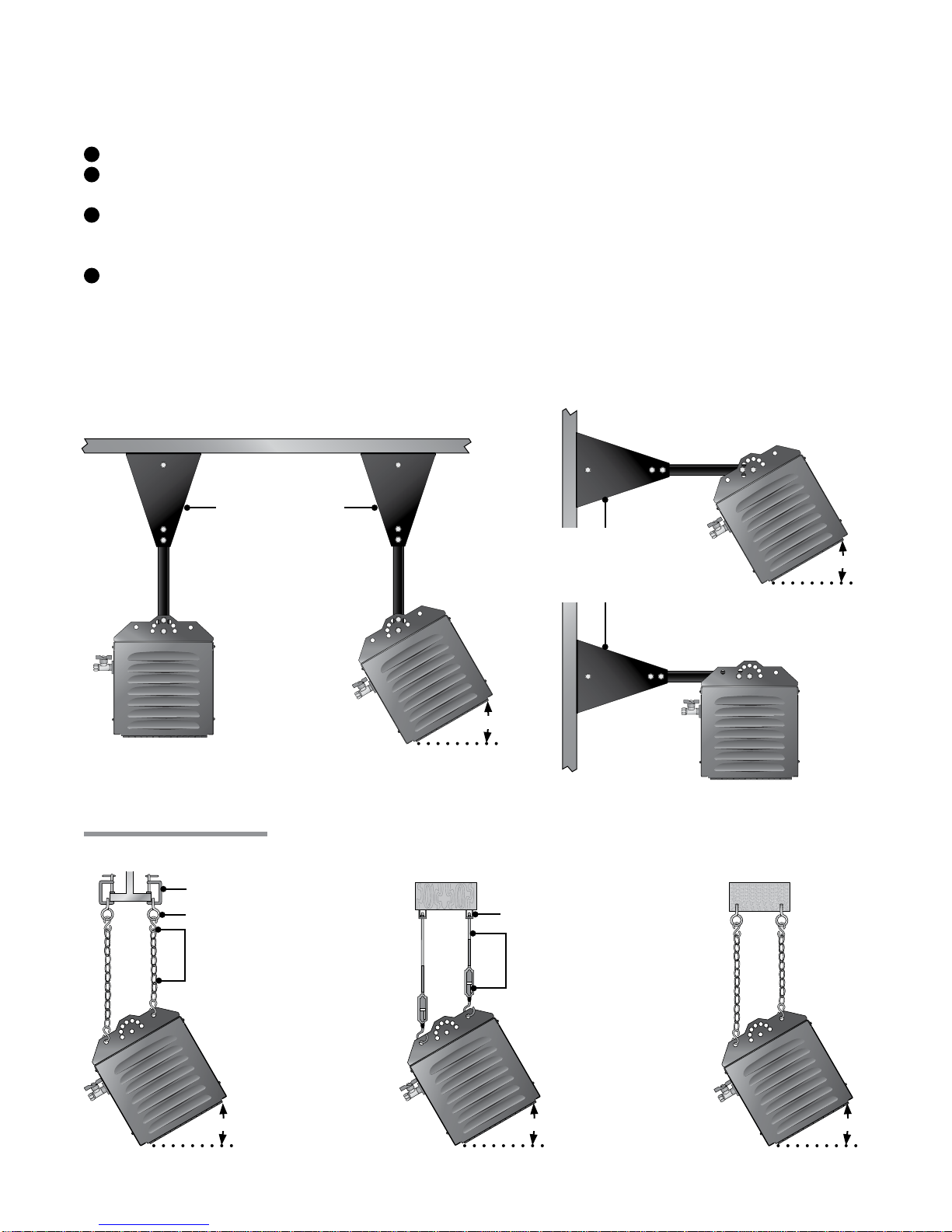
Figure 2.3 illustrates the most common methods for heater mounting. Depending on the type of mounting
you use, be sure to:
Prepare mounting surface. If necessary, weld blocks to mounting structure, drill holes, etc.
Fasten beam clamp, screw hook or other type of suspension anchor to hanging point.
Attach and close S-Hook (P/N: S-HOOK) and #1 double-loop chain (P/N: THCS includes a 1524 mm
chain and two S-hooks, four required) to anchor. Check that it is securely attached.
Attach heater to chains. Adjust chain lengths until the heater is level and equal weight distribution is
achieved. Chains must be straight up and down, do not install chains at an angle.
NOTE: Conditions that would cause the unit to move (e.g. wind drafts, blowers, crane rails, etc.) or codes
may require the heater to be rigidly mounted.
Optional mounting
bracket (PH-BKT)
attached to ceiling. Optional mounting
bracket (PH-BKT)
attached to wall.
Figure 2.3 • Common Heater Mounting
0-30°
0-30°
0° Mounting Angle
30° Mounting Angle
30° Mounting Angle0° Mounting Angle
2.0 Installation • Mounting the Heater
Steel C-clamp
Screw Hook
S-Hook and
#1 double-loop
chain (recommended)
Bar Joist Clip
Rigid threaded rod
and turnbuckle
(field supplied)
Wood Beam
I-Beam Concrete Beam
0-30° 0-30° 0-30°
Other Heater Mounting
1
2
3
4

30˚
10
2.0 Installation • Clearance to Combustibles
Figure 2.4 • Clearance to Combustibles
Below
Side Side
End
END VIEW
0° ANGLE
Top
Clearance to Combustibles
When installing the infrared heater system, the minimum clearances to combustibles must be maintained.
These distances are shown in Table 2.2 and on the minimum clearance to combustibles label
(F/N: LLPCL003) found on the heater.
WARNING
!
Failure to comply with the published clearances to combustibles could result in personal
injury, death and/or property damage.
In locations used for the storage of combustible materials, signs must be posted to
specify the maximum permissible stacking height to maintain the required clearances
from the heater to the combustibles. Signs must either be posted adjacent to the heater
thermostats or in the absence of such thermostats, in a conspicuous location.
Table 2.2 • Clearance to Combustibles in millimeters (see Figure 2.4)
Certain applications (awnings, fabrics, plastics, sprinklers, insulation) may require the heater to be
mounted at a distance in excess of the published clearances to combustibles. Contact the factory.
IMPORTANT! If the heater is mounted beneath a non-combustible surface a 200 mm minimum top
clearance must be maintained from the top of the heater to prevent overheating the controls.
Model No. Mounting
Angle* Sides Behind Top Below End(s) Front
GPH 9
(9 kW) 0° 360 N/A 330 1170 560 N/A
30° N/A 200 430 1170 560 1170
GPH 10
(10 kW) 0° 360 N/A 330 1170 560 N/A
30° N/A 200 430 1170 560 1170
* Heaters mounted on an angle between 0° to 30° must maintain clearances posted for 0° or 30°;
whichever is greater.
Front
Behind
Below
Top
END VIEW
30° ANGLE SIDE VIEW
End
10 11
2.0 Installation • Gas Supply
Gas Supply
WARNING
!
IMPORTANT! Before connecting the gas supply to the infrared heater(s):
• This appliance must be used on a governed gas supply.
• Gas and electrical lines must not be located in the path of exhaust or in direct contact with infrared rays.
• Check for conditions such as drafts or other variables which might cause excessive movement of the
unit and cause damage to the gas connection. Ensure that the unit is securely mounted and connect the
gas with an approved connection device suitable for the environment of use.
• The gas supply to the heat must terminate with an isolation cock and a flexible connector. This will
allow the heater to be disconnected for maintenance or repair. The gas outlet shall be in the same room
as the appliance and the gas connector must not be concealed within or run through any wall, floor or
partition.
• All pipe work must be supported and installed in accordance with the regulations listed on page 5 and
provide the required operating gas pressure and volume for the appliance. Pipes of a smaller size than
the heater inlet gas connection must not be used. Consult gas company for correct sizing.
• The final connection is made to the heater gas valve. This has a pipe thread EN 10226 Rp 3/8”. A
flexible metallic hose conforming to B.S. 6501:1991 (minimum specification type B Class 1) must be
used for this purpose. This must be kept clear of the flue products opening at the top of the heater and
should be of adequate length.
• Take care when making the final connection to the gas valve not to apply excessive turning force to the
gas valve. Always use two wrenches when tightening mating piping connections.
• If all or a portion of the gas supply line consists of used pipe, it must be cleaned and then inspected to
determine its equivalency to new pipe.
• Pressure test all main supply lines according to local codes. Isolate the heater gas valve and supplied
ball valve during this test.
• Test the final connection to the heater for leaks according to the relevant codes of practice.
WARNING
!
Testing for gas leaks with an open flame or other sources of ignition may lead to a fire or
explosion and cause serious injury or death. Test in accordance with relevant codes of
practice.
Failure to install, operate or service this appliance in the
approved manner may result in property damage, asphyxiation,
injury or death. This heater must be installed and serviced by
Gas Safe Registered Gas Engineers and service personnel only.
The installation of this heater must conform to the requirements of EN 14543:2005 and other relevant
standards.
12
2.0 Installation • Gas Supply
Table 2.3 • Gas Pressure
The following information is valid for heaters supplied in the UK and Ireland using either natural gas or
propane fuel. Please check heater data plate and packaging to verify fuel type. Refer to page 21 for
information on converting heater for use in other countries.
NOTE: The gas pressure governor has been factory preset.
Gas Supply from LPG Cylinders
This heater may be supplied with LP gas from cylinders. It is essential the propane gas cylinders used
are sufficiently sized to ensure an adequate supply of gas to the heater. This heater is intended to be
permanently installed and supplied with gas via a metal piping system. Flexible tubing or hose is not
recommended.
A suitable regulator must also be used to supply the correct inlet pressure and gas flow rate to the
heater. A minimum flow rate of 0.72 kg/h is required. The maximum regulator pressure is 37 mbar.
Gas cylinders should not be located in any position where it is exposed to direct heat from the heater.
All relevant standards and local codes must be complied with when choosing a location for the gas
cylinders.
Consult the gas supplier for further information on propane cylinders, regulators and cylinder location.
When using LPG Cylinders
• Change the gas cylinder in an amply ventilated area, away from any ignition source (such as
candles, cigarettes or other flame producing sources).
• Check that the regulator seal is properly fitted and able to fulfill its function.
• In the event of a gas leakage, the appliance shall not be used and the gas supply shall be shut off
and the issue investigated and rectified before using the appliance.
• Check the gas piping at least once per month and each time the cylinder is changed.
• Ensure that the tightness of the cylinder’s regulator connection is adequate to ensure the no gas
leakage can occur.
Table 2.4 • LPG Cylinder Information
Type of Gas Burner Pressure
Setting Minimum Inlet
Pressure Maximum Inlet
Pressure
Natural (G20) 12.5 mbar 15 mbar 20 mbar
Liquefied Petroleum (G31) 26.5 mbar 30 mbar 37 mbar
13
2.0 Installation • Electrical Requirements
WARNING
!
This heater must be earthed.
Incorrect or improper wiring may result in shock, injury or death. Do not touch the
ignition, flame detection electrodes or any part of the circuitry while the power is
connected to the heater. These parts carry high voltage at all times and will produce an
electric shock if touched.
A 230V-50Hz single phase supply is required.
All wiring must comply with I.E.E. and local authority recommendations. The main lead wiring used on
this appliance is colored in accordance with the following:
Earth: Green and Yellow
Neutral: Blue
Mains: Brown
NOTE: If the mains lead is damaged, it must be replaced by a special cord or assembly available from the
manufacturer or distributor.
The method of connection to the electrical supply must facilitate complete isolation and should
preferably be made via a fused double pole isolator having a contact separation of at least 3 mm in all
poles and supply the appliance only. An alternative connection may be made via a fused three pin plug
and an unswitched shuttered socket both complying with the requirements of B.S. 1363.
Ensure that live, neutral and earth are connected properly as the flame detection circuit will not operate
if polarity is reversed.
A thermostat may be installed to control the heater in indoor applications if desired. The thermostat
should be located in the heated area at a height of approximately 1.5 m above floor level and in a
position where it is not directly irradiated by the heater. The use of thermostats in outdoor locations is
not recommended.
Electrical Requirements
IMPORTANT! Radiant heat may damage the flexible power cord. Always keep the flexible power cord
away from the heater. Do not allow the power cord to be subjected to radiant heat.

14
2.0 Installation • Ventilation
Ventilation
WARNING
!
Improper or insufficient ventilation may result in explosion, fire, health problems, carbon
monoxide poisoning or death. Vent enclosed spaces and buildings according to relevant
applicable codes.
This heater may only be used in outdoor residential applications or indoor/outdoor
commercial (or industrial) applications. This heater is not approved for use in indoor
domestic applications and must never be installed indoors in the home.
Figure 2.5 • Hot Flue Discharge
Discharge released from
side air channels. Keep
area clear of gas piping
and electrical wiring.
Ventilation requirements vary according to the type of installation. The installation should be carried out
by a qualified installer.
The space to be heated must be ventilated to remove the products of combustion and to provide an
adequate supply of fresh air. Ventilation may be provided by natural or mechanical means. Exhaust
opening for the removal of flue products must be above the level of the heater(s).
Ventilation requirements in accordance with BS EN 13410:2001 must be adhered to. The the volume of
fresh air entering the building should be at least 37.5 m3/h per kW of total rated heat input. The minimum
air volume requirement must comply with BS 6896:2005.
Example:
One GPH 10 is rated at 10.0 kW
Ventilation requirement = 10.0 x 37.5 m3/h
Ventilation requirement = 375 m3/h
This heater must be installed outdoors or in an amply ventilated area. An amply ventilated are must have
a minimum of 25% of the surface area open. The surface area is the sum of the wall surface.
See Figure 2.6.
Figure 2.6 • Surface Area for Ventilation

15
3.0 Operation
3.0 Operation • Pre-Commissioning Check
Important! Before operating the heater, conduct the following safety procedures:
• Check for any possible gas leaks.
• Alert all persons about the hazards of high surface temperature and to keep a safe distance away
in order to avoid burns and possible clothing ignition.
• Provide supervision when young children are in the area of the heater.
• Check to make sure clothing isn’t hung from the heater and that flammable materials are not
placed on or near the heater.
• Check that all guards or protective devices are in place and secure.
• Check the hose assembly for excessive abrasion, wear or damage. If necessary replace.
• Check control compartment, burners and circulating air passages for debris. If necessary, clean
the debris.
WARNING
!
Improper operation of the heater may result in explosion, fire, shock and
carbon monoxide poisoning. Follow all guidelines and warnings in this manual
and relevant applicable codes. Always conduct safety checks before
operating the heater. Do not operate the heater in unsafe conditions.
Pre-Commissioning Check
Inspect ceramic plaques to ensure that none have been damaged. If any cracks are detected, the heater
must not be commissioned until the affected burner unit has been replaced (see section 4.0 Maintenance).
If compressed air is used to detect leaks in the gas supply line, disconnect and cap the ball valve to avoid
damage to the regulator and gas valve.

16
Ensure that the service cock to the heater is turned off.
Purge air from gas supply and test for gas soundness in accordance with the relevant standards. See
page 5.
Check that all electrical connections are made to the heater and that the unit has a sound earth
connection.
Release burner setting pressure test point screw on the gas valve by rotating one turn counter-
clockwise. Connect the pressure gauge via the outlet pressure test point.
Open the gas service cock and close the control compartment door.
Switch on the power to the heater via remote electrical switch. After a purge period lasting a few
seconds, the solenoid valves will open and the heater will come into operation having been lit by the
electrical spark.
Check burner setting pressure. This should be set according to Table 2.3 on page 12.
The pressure governor on the gas valve has been factory preset to the correct operating pressure. If
the correct operating pressure is not measured then it may be necessary to re-adjust. Please see
page 21 for details of how this is performed.
When the correct pressure is measured, switch off the heater. Remove the pressure gauge. Tighten
the test point screw.
Test the supply between the service cock and the heater for gas soundness.
Fit the low level lighting instruction plate.
The heater is now ready for use.
Commissioning
Switching on the Heater
Ensure that the gas supply to the heater is turned on.
Ensure that the thermostat and/or time clock is calling for heat.
Switch on the electrical supply to commence the ignition sequence.
There is a delay of approximately ten seconds. The burner is then ignited by the electrical spark.
If ignition fails, the heater will make two attempts before locking out.
If lockout occurs, shut off the power supply and restore after 30 seconds. If lockout re-occurs
more than three times, switch off the heater and call a service technician.
Switching off the Heater
Switch off the electrical supply to the heater. The burner will be extinguished.
NOTE: If the heater is to be switched off for more than one month, it is recommended that both
the electrical and gas supplies are turned off.
3.0 Operation • Commissioning
1
2
3
4
5
6
7
8
9
1
2
3
4
5
17
16
GPH Series 230V-50Hz Amp draw:
.15 starting
.15 running
This heater features a fully automatic ignition and control system. When power is supplied to the heater,
the gas valve opens allowing gas to enter the burner. A spark is generated at the ignition electrode which
ignites the gas.
After ignition, the sparking ceases and the flame rod on the electrode monitors the flame as the heater
commences normal operation.
If the flame is not established, the spark is interrupted after a few seconds and the gas valve closes. The
heater will make two attempts to ignite before entering lockout. The power supply to the heater must be
switched off and then switched back on before another ignition attempt is made.
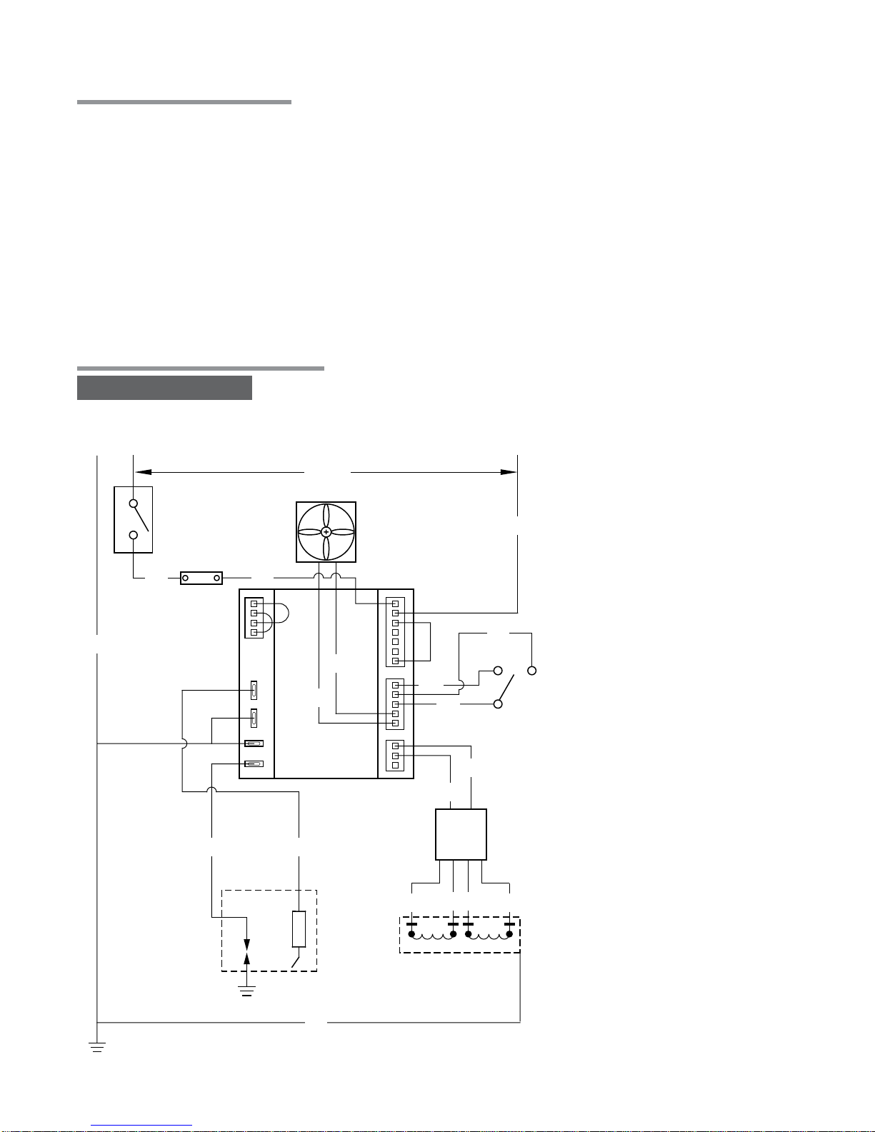
Sequence of Operation
3.0 Operation • Sequence of Operation • Heater Control Wiring
Figure 3.1 • Heater Control Wiring
230V
Fan
Gas Valve
Electrode
Assembly
BL
BR
BR
BL
BL
BR
W
BR BL
OO
Pressure
Switch
Circuit
Board
W
BK
GR NO
NC
Thermal
Switch
O230-115V
Rectifier
G
G
Door
Switch
NO
BR
NL1
18
WARNING
!
4.0 Maintenance
Electrical shock or explosion may occur when conducting maintenance while the heater
is connected to the power source and gas supply. Disconnect power and gas supply to
heater before servicing.
Do not touch the ignition or flame detection electrodes or any part of the ignition/flame
detection circuitry while power is supplied to the heater. These parts carry high voltages
at all times and will produce an electric shock if touched.
This heater requires annual service in order to ensure continued safe and efficient operation.
Periodic maintenance:
• Clean the heater with cleaning agents suitable for the unit’s construction material.
NOTE: Stainless steel cleaner is recommended on stainless steel surfaces.
• Inspect the gas supply piping system for signs of corrosion or failure. Replace if necessary.
Annual maintenance is normally sufficient unless abnormal site conditions necessitate that such work be
carried out at more frequent intervals (e.g. dusty environments, etc.).
The following service procedure should be followed:
Turn OFF the electrical isolating switch and gas cock.
Remove dirt and other deposits form all heater surfaces. Low pressure compressed air may be used
to clean ceramic plaques and venturies. Air hose pressure must not exceed 200kPa or 30psi as it
could cause damage to the heater elements and cause equipment failure. Gently pass the air hose
over the entire exposed area of the ceramic. A distance of 600-1200 mm from the unit is
recommended.
Remove and clean the injector.
Check that:
• All ceramic plaques are free from cracks or damage.
• The heater fixing arrangements are satisfactory.
• The flue products outlet is free of obstructions.
• The minimum clearances between the various heater surfaces and combustible materials are
preserved.
Re-commission the heater as outlined in section 3.0 Operation.
Switch OFF the heater. Close the gas service cock if the heaters are not to be used for an extended
period. During long periods of non-usage, remove or cover heater with a polyethylene bag and shut
off gas supply. If further service to the heater is desired, contact your distributor.
4.0 Maintenance • Periodic Maintenance
1
2
3
4
5
6
19
4.0 Maintenance • Troubleshooting • Replacement Procedures
Troubleshooting
Symptom:
Power is connected to the heater, but nothing happens.
Remedy:
Check the electrical supply and all electrical connections. If this reveals nothing, it is likely that the fan,
gas controller or pressure switch has failed. Check the fan, pressure switch and controller sequence.
Replace as necessary.
Symptom:
The electrode sparks, but the heater fails to ignite.
Remedy:
Check the heater inlet gas pressure (test point located on gas valve). This should be at least 18 mbar
for natural gas or 30 mbar for propane.
Check electrode spacing (3 mm gap recommended).
Check gas valve operation. Replace if necessary.
Replace controller if the valve is not defective.
Symptom:
The heater ignites satisfactory, but it switches off after a short period.
Remedy:
Check electrode spacing (3 mm gap recommended. A 3 mm clearance should also be maintained to
the surface of the ceramic plaques).
If this does not resolve the problem, replace the controller.
Symptom:
A burner does not reach its normal operating temperature (orange color) and a loud,
roaring noise is audible.
Remedy:
This indicates that the burner has flashed back. The condition is caused by damage to the ceramic
plaques. Replace the burner unit.
Replacement Procedures
Replacement of gas controller:
Switch OFF electrical and gas supplies.
Unscrew the screw which retains the hinged
cover of the control enclosure.
Disconnect all electrical connection from the
control box terminals.
Unscrew the two screws which retain the gas
controller in place. Lift controller clear.
Replace controller and re-assemble.
Re-commission the heater. Gas controller retaining screw
Figure 4.1 • Control Enclosure
1
2
3
4
5
6

20
Replacement Procedures
Replacement of gas valve (see Figure 4.2):
Switch OFF electrical and gas supplies.
Disconnect the electrical connections from gas valve.
Disconnect the inlet gas connector from the heater.
Unscrew the inlet gas pipe from gas valve inlet.
Unscrew the brass fitting from gas valve outlet.
Remove gas valve.
Replace valve and re-commission heater.
Replacement of electrode set (see Figure 4.3):
If electrodes are damaged, they must be replaced
complete with holder.
Switch OFF electrical supply and gas service cock.
Disconnect the leads from electrode.
Remove the electrode set from mounting bracket by
unfastening the retaining screws.
Replace with the new electrode set.
Re-assemble and re-commission the heater.
Replacement of Burner (see Figure 4.4):
If the ceramic plaques are damaged, it is necessary
to replace the entire burner assembly.
Remove the four nuts and bolts which retain the
burner unit to the heater frame.
Remove burner and replace.
Re-commission heater.
Replacement of Pressure Switch (see Figure 4.5):
If the pressure switch fails, it is necessary to replace it.
Disconnect the wiring.
Remove the retaining screws; retain.
Disconnect the pipes.
Replace the switch, refasten screws, connect pipes
and reconnect the wiring.
Re-commission the heater.
4.0 Maintenance • Replacement Procedures
Burner setting pressure test point
Inlet pressure
test point
Burner setting pressure
adjustment screw
Electrode retaining
screws
Burner retaining screws
Figure 4.2 • Gas Valve
Figure 4.3 • Electrode
Figure 4.4 • Burner Assembly
Figure 4.5 • Pressure Switch
1
2
3
4
5
7
6
1
2
3
4
5
1
2
3
1
2
3
4
5
Table of contents
Popular Patio Heater manuals by other brands

Blumfeldt
Blumfeldt 10035250 manual

Solaira
Solaira Alpha H3 SALPHAH3-30240LL-C Reference manual

Blumfeldt
Blumfeldt Heatbell Tower manual

Sunred
Sunred RD-SILVER-2000W Translation of the original instructions

SunGlo
SunGlo PSA 265 Installation, operation & maintenance manual

Parasol
Parasol OZGLOW HE40 Installation, operation and maintenance instructions


Brander
Brander TR6029 NG User installation and operation guide

IR Energy
IR Energy HABANERO HAB Series Manual for installation, operation & maintenance

Lehner Versand
Lehner Versand ZHQ2566-RM-S instruction manual

Hiland
Hiland BURN-2400-BRZ manual

Hiland
Hiland GS-2400-BLK manual

Hortus
Hortus 211-377 instructions