RADWAG MW-01 Series User manual


2
FEBRUARY 2021

3
PRECAUTIONS
Prior to installation, operation or maintenance activities, carefully read this user
manual. Follow the instructions strictly.
Prior to the first use, carefully read this user manual. Use the device only
as intended.
Protect the device against considerable temperature variation, solar and
UV radiation, substances causing chemical reactions.
The device must not be operated in hazardous areas endangered with
explosion of gases, and in dusty environments.
In the case of damage, immediately unplug the device from the mains.
The device to be decommissioned must be decommissioned in
accordance with valid legal regulations.
If the module is to be operated in conditions that are difficult due to
electrostatics (e.g. printing house, packing centre, etc.), you must connect
it to the earth wire. To enable this, the device features functional earthing
terminal, marked with symbol.

4
CONTENTS
1. INTENDED USE .................................................................................................................................................5
2. WARRANTY CONDITIONS ...............................................................................................................................5
3. MAINTENANCE..................................................................................................................................................5
4. SERVICE AND REPAIR.....................................................................................................................................6
5. RECYCLING.......................................................................................................................................................6
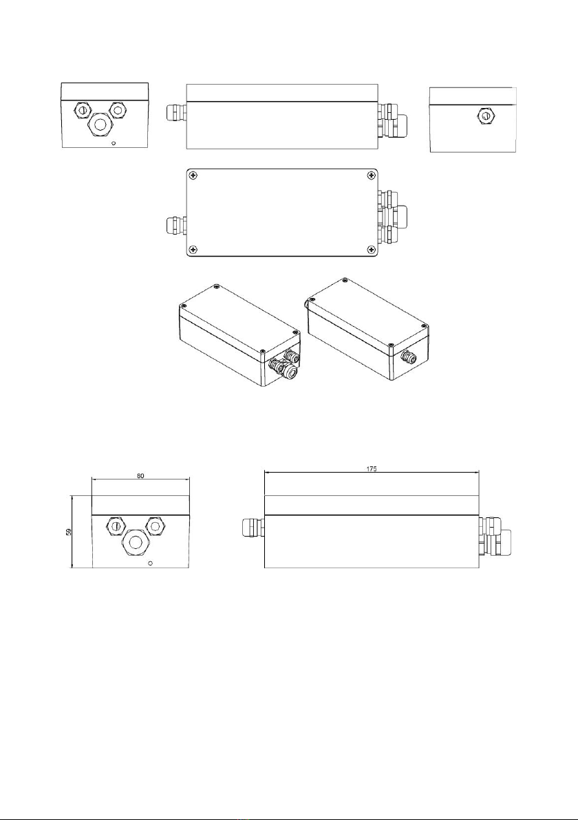
6. MECHANICAL DESIGN..................................................................................................................................... 6
6.1.General View................................................................................................................................................7
6.2.Dimensions...................................................................................................................................................7
6.3.Connectors...................................................................................................................................................7
6.3.1.RS232 Connector................................................................................................................................8
6.3.2.RS485 Connector................................................................................................................................8
6.3.3.Ethernet Connector .............................................................................................................................8
6.3.4.PROFIBUS Connector ........................................................................................................................8
6.4.Diagrams of Connection Cables..................................................................................................................9
6.5.Technical Specifications.............................................................................................................................10
6.5.1.IN/OUT Parameters...........................................................................................................................11
7. INSTALLATION................................................................................................................................................11
7.1.Unpacking and Installation.........................................................................................................................11
7.2.START-UP .................................................................................................................................................12
8. INSTALLER INSTRUCTION............................................................................................................................12
8.1.6-Wire Load Cell Connection.....................................................................................................................12
8.2.4-Wire Load Cell Connection.....................................................................................................................13
8.3.Connecting Load Cell’s Cable Shield.........................................................................................................14
9. FACTORY PARAMETERS ..............................................................................................................................14
9.1.Factory Parameter Access.........................................................................................................................14
9.2.Factory Parameters....................................................................................................................................15
9.3.Parameter Value Modification....................................................................................................................16
9.4.Factory Adjustment ....................................................................................................................................16
9.4.1.Start Mass Determination..................................................................................................................16
9.4.2.Adjustment Factor Determination......................................................................................................17
9.5.Gravitational Correction .............................................................................................................................17
9.6.Linearity Correction....................................................................................................................................18
10. ERROR MESSAGES .....................................................................................................................................19

5
1.INTENDED USE
The MW-01 mass converter is designed to be a component of an industrial
load cell scale. Depending on the needs, communication with the mass
converter can be carried out via the following communication interfaces:
RS232, RS485, Ethernet, Profibus, and Modbus protocol. The MW-01 mass
converter can connect with PUE 5.15, PUE 5.19 indicators or a PC.
Operation of the MW-01 mass converter via PC is carried out using
MwManager software. For more information on the MwManager software read
MwManager manual.
2.WARRANTY CONDITIONS
A. RADWAG is obliged to repair or exchange all elements that appear to be
faulty by production or by construction.
B. Defining defects of unclear origin and means of their elimination can only
be realized with the assistance of the manufacturer and the user
representatives.
C. RADWAG does not bear any responsibility for damage or losses
resulting from unauthorized or inadequate performing of production or
service processes.
D. The warranty does not cover:
mechanical damage caused by product exploitation other than
intended, damage of thermal and chemical origin, damage caused by
lightning, overvoltage in the power network or other random event,
inappropriate cleaning habits.
E. Loss of warranty takes place if:
a repair is carried out outside RADWAG authorized service point,
service claims intrusion into mechanical or electronic construction by
unauthorized people,
the scale does not bear security seal stickers.
F. Warranty conditions outline the warranty period for rechargeable
batteries attached to the device for 12 months.
G. For detailed warranty conditions read the service card.
H. Contact with the central authorized service: +48 (48) 386 63 30.
3.MAINTENANCE
In order to clean the weighing instrument risk-free, it is necessary to disconnect
the device from the mains. Avoid using cleansers containing any corrosive
chemicals, e.g. bleach (with chlorine). Do not use cleansers containing
abrasive substances. Always remove the dirt using microfiber cloth to avoid
damage of protective coating.

6
In the case of a daily maintenance:
1. Remove the dirt using cloth dipped in warm water.
2. For best results, add a little bit of dishwashing detergent.
4. SERVICE AND REPAIR
In the case of any sign of damage, it is necessary to
disconnect the device form the mains immediately. The
damaged component must be replaced or repaired by
RADWAG service directly.
In the case of any problems with correct operation of the device, contact the
closest manufacturer's service point.
In the case of defects, deliver the faulty product to the manufacturer's service
point. If the product cannot be delivered to the manufacturer's service point, call
the service and report the defect. Repair scope and method will be set up.
The user is NOT ALLOWED to carry out any kind of repair of
the device himself/herself. Any attempt of module
modification, repair etc., by unauthorized persons, will result
with loss of validity of manufacturer-issued certificates,
declarations and warranty.
5. RECYCLING
MW-01 mass converters must be recycled, they are not to be treated as a
regular household waste. Devices to be decommissioned must be
decommissioned in accordance with valid legal regulations.
6.MECHANICAL DESIGN
The MW-01 mass converter is equipped with metal housing. Signal cables are
fed through cable glands. Communication with peripheral devices is carried out
via one of the following communication interfaces: RS485, RS232, Ethernet,
Profibus. It is equipped with 2 optoisolated inputs, 2 reed switch outputs and a
high speed transistor output. It is powered with 8÷30VDC voltage.

7
6.1. General View
MW-01 mass converter, general view
6.2. Dimensions
MW-01 mass converter, dimensions
6.3. Connectors
MW-01 mass converter ver1 features RS232, RS485, Ethernet cables, they are
fed through cable glands. MW-01 mass converter ver2 features 2 connectors,
PROFIBUS IN and PROFIBUS OUT, and RS232 cable fed through the cable
gland.

8
Arrangement and description of connectors on the main board of the MW-01.
6.3.1. RS232 Connector
Signals are transmitted via cable fed through a cable gland M16. The cable
is connected to joint J5 of the main board of MW-01 mass converter.
6.3.2. RS485 Connector
Signals are transmitted via cable fed through a cable gland M16. The cable
is connected to joint J5 of the main board of MW-01 mass converter.
6.3.3. Ethernet Connector
Signals are transmitted via cable fed through a cable gland M16. The cable
is connected to Ethernet module (board 218Rxxx mounted to joint J2 of the
main board of MW-01 mass converter.
6.3.4. PROFIBUS Connector
The MW-01 ver2 mass converter is equipped with input and output connectors
for PROFIBUS. On the output connector there is 5 VDC voltage, this provides
correct operation of a terminator. M12 5 pin B coded connectors are installed
(for PROFIBUS DP).

9
Pin arrangement
PROFIBUS IN
(male)
Pin1 –NC
Pin2 –A
Pin3 –NC
Pin4 –B
Pin5 –NC
PROFIBUS OUT
(female)
Pin1 - +5V
Pin2 –A
Pin3 –GND
Pin4 –B
Pin5 –NC
6.4. Diagrams of Connection Cables
'Mass converter’–'RS232' cable (PT0145)
'Mass converter' –'RS485' cable (PT0012)

10
'Mass converter' –'Ethernet' cable (PT0014)
'Mass converter' –'IN/OUT' cable (PT0146)
6.5. Technical Specifications
MODEL
MW-01 ver.1
MW-01 ver.2
Communication interface
RS232, RS485,
Ethernet
RS232, PROFIBUS
Power supply
8 ÷ 30 VDC
Housing
metal
Ingress protection
IP 66
Operating temperature
-10 °C ÷ 40 °C
OIML class
III

11
Verification units
10 000
Maximum input signal gain
19.5 mV
Minimum voltage per verification unit
0.5 µV
Minimum load cell impedance
80 Ω
Maximum load cell impedance
1200 Ω
Load cell excitation voltage
5 VDC
Load cell type
4 or 6 wires + shield
Platform quantity
1
2IN/3OUT
Standard
RS232 RS485 baud rate
57600 bit/s by default
6.5.1. IN/OUT Parameters
The mass converter is equipped with 2 optoisolated inputs, 2 reed switch
outputs and a high speed transistor output (open collector type).
OUT1 –OUT2 Parameters
Output quantity
2
Output type
NO type reed switch
Cable cross-section
0.14 - 0.5 mm2
Maximum output current
200 mA
Maximum output voltage
50 VDC
OUT3 Parameters
Output quantity
1
Output type
Transistor
Umax
5 VDC
Imax
100 mA
Input parameters
Input quantity
2
Input type
Optoisolated
Cable cross-section
0.14 - 0.5 mm2
Input voltage range
5 - 24 VDC
7. INSTALLATION
7.1. Unpacking and Installation
A. Take the mass converter out of the packaging.

12
B. Connect the weighing platform to the mass converter, next place the
weighing device on a flat and even surface. Keep it away from any
sources of heat.
C. Level the device.
Levelling procedure is to be found in 'TWM1 Scale' user
manual.
7.2. START-UP
Plug the power supply to the mains.
Wait for connection to be established between the mass converter and the
MwManager software, read the weighing result.
The procedure of communication establishing and a detailed
description of connection between the device and the
‘MwManager’software is to be found in the ‘MwManager’
user manual.
8.INSTALLER INSTRUCTION
The MW-01 mass converter can be a base component of a load cell scale.
8.1. 6-Wire Load Cell Connection
Connect 6-wire load cell to the main board following the diagram below:
6-wire load cell connection

13
Connection
Load cell signal
REMARKS
E
SHIELD
Refer to section 8.3
REF+
SENSE +
JP1 not to be soldered
REF-
SENSE -
JP2 not to be soldered
IN+
OUTPUT+
IN-
OUTPUT-
+EXC
INPUT+
-EXC
INPUT-
8.2. 4-Wire Load Cell Connection
Connect 4-wire load cell to the main board following the diagram below:
4-wire load cell connection
Connection
Load cell signal
REMARKS
E
SHIELD
Refer to section 8.3
REF+
-
JP1 soldered
REF-
-
JP2 soldered
IN+
OUTPUT+
IN-
OUTPUT-
+EXC
INPUT+
-EXC
INPUT-

14
8.3. Connecting Load Cell’s Cable Shield
Scale with a mass converter in
a metal housing connected with
a platform via a load cell signal
cable.
Scale of compact mechanical design,
mass converter in a metal housing
connected with a platform via an
extension arm, etc.
Platform w/o galvanic
connection of the signal
cable shield.
POINT A
E
Platform with galvanic
connection of the signal
cable shield.
POINT A
POINT A
Point A –electrical connection with the housing.
E–solder pad on A/D converter board.
9.FACTORY PARAMETERS
In order to be able to edit and save factory parameters to the MW-01 mass
converter's memory, it is necessary to put a jumper allowing access to the
factory parameters.
9.1. Factory Parameter Access
Plug the power cord to the mains.
Put jumper to JP3 on the electronics board.
Factory parameters’ access jumper

15
Wait for connection to be established between the mass converter and the
'MwManager’software, go to <Parameters / Factory parameters>
submenu.
Factory parameters are set into groups: Adjustment, Weighing,
Information, Converter. To access a given group, select a respective tab.
Factory parameter window
9.2. Factory Parameters
NAME
DEFAULT
VALUES
REMARKS
Adjustment
-
-
-
Range
3.009
-
Maximum range + 9e overload.
Range 2 threshold
0
-
Switching point of range II. For single range
balances set 0.
Range 3 threshold
0
-
Switching point of range III. For I-range
or II-range scales set 0value.
Reading unit: range 1
0.001
0.001 50
Rounding of the last digit and position
of a decimal point for weighing range I.
Reading unit: range 2
0.001
0.001 50
Rounding of the last digit and position
of a decimal point for weighing range II.
Reading unit: range 3
0.001
0.001 50
Rounding of the last digit and position
of a decimal point for weighing range III.
Adjustment weight
3
-
Adjustment weight mass.
Adjustment unit
kg
g, kg, lb
Adjustment (calibration) unit.

16
Verified
NO
YES - NO
Declaring whether the scale is verified or not.
YES - verified scale, NO - non-verified scale.
Determine start mass
-
-
Start mass determination (refer to section
9.4.1).
Determine adjustment
factor
-
-
Adjustment factor determination (read section
9.4.2).
Set defaults
-
-
Restoring default adjustment parameter
settings.
Weighing
-
-
-
Autozero range
0.25
0.1 ÷ 5
Autozero range (in divisions).
Stability range
1
0.1 ÷ 5
Stability range in [d] units.
Stability time
0.8
0.1 ÷ 5
Stability time, given in seconds.
Start mass control
1
0, 1, 2
Start mass control: 0–disabled, 1–range:
from -5% to +15% of start mass, 2–range:
from -20% to +20% of start mass.
Information
-
-
-
A/D divisions
-
-
Current quantity of converter divisions.
Adjustment factor
100
-
Adjustment/calibration factor.
Start mass
100
-
Start mass value (in divisions).
Gcor
1
-
Gravitational correction factor (refer to section
9.5).
Serial number
-
-
Serial number of the mass converter.
Adjustment qty counter
-
-
The quantity of factory parameter recordings.
Converter
-
-
-
Converter rate
6,25
6.25 ÷ 1600
Converter rate change.
9.3. Parameter Value Modification
Select a parameter, enter/modify its value.
Press <Save> button, Message <Save parameters?> is displayed.
Press <Yes> button to confirm, message <Changes saved> is displayed.
Press <OK> button to confirm.
9.4. Factory Adjustment
9.4.1. Start Mass Determination
Unload the weighing pan.
Go to <Adjustment> tab, press <Determine start mass> button,
message <Unload the pan> is displayed.
Press <OK.> button to confirm, start mass adjustment begins.

17
Upon completion, message <Start mass determination completed
successfully> is displayed.
Press <OK> button to confirm.
Press <Save> button, message <Save parameters?> is displayed.
Press <Yes> button to confirm, message <Changes saved> is displayed.
Press <Yes> button to confirm. Determined start mass gets saved to
converter's memory.
9.4.2. Adjustment Factor Determination
Unload the weighing pan.
Press <Determine adjustment factor> button, message <Unload the
pan> is displayed.
Press <OK.> button to confirm, start mass adjustment begins.
Upon completion, message <Load xxx> (where: xxx –declared
adjustment weight mass).
Load the weighing pan with weight of specified mass value and press
<OK> button.
Upon completion, message <Adjustment factor determination
completed successfully> is displayed.
Press <OK> button to confirm.
Press <Save> button, message: <Save parameters?> is displayed.
Press <Yes> button to confirm, message: <Changes saved> is displayed.
Press <Yes> button to confirm. Determined adjustment factor gets saved
to converter's memory.
9.5. Gravitational Correction
The function of gravitational correction compensates changes of earth gravity
being a result of different latitude and longitude. It enables correct calibration of
the weighing device away from the place of use. The gravitational correction
value must be entered with reference to tables prepared by „Radwag Balances
and Scales” or calculated using the below formula:
kal.
uzyt.
g
g
Gcor
Correction value ranges between 0.90000 ÷ 1.99999.
If the scale is calibrated at the place of use then the
gravitational correction value (<g-cor.> parameter) is 1.00000.
If the scale is calibrated away from the place of use
(longitudinal change) the value of <g-cor.> parameter must be
corrected.

18
9.6. Linearity Correction
„Linearity” tab enables access to thresholds and linearity deviations.
Linearity correction window
Where:
Press to zero all threshold values. To zero the deviations and the
thresholds, select <Zero thresholds while zeroing linearity> option.
Press to zero a value of a particular threshold / deviation.
Press to determine deviation of a particular threshold.
Procedure:
Enter linearity threshold values.
Press particular threshold button, , message <Load xxx> (where: xxx
–entered mass value) is displayed.
Load the weighing pan with declared mass and press <OK> button.
Deviation is calculated automatically and entered in the linearity threshold
deviation field.
Determination of deviations for remaining linearity thresholds proceeds
analogously.
Press <Save> button to save changes, message <Save parameters?> is
displayed.
Press <Yes> button to confirm, message <Changes saved> is displayed.
Press <Yes> button to confirm.

19
10. ERROR MESSAGES
Err2
Value out of zero range.
Err3
Value out of tare range.
Err8
Taring/zeroing time out of range.
NULL
Zero value from converter.
FULL
Weighing range exceeded.
HI
Display capacity out of range.
LH
Start mass error, indication out of range (-5% –+15% of start mass).

20
Other manuals for MW-01 Series
2
Table of contents
Other RADWAG Media Converter manuals