RADWAG MW-04 User manual


2
FEBRUARY 2021

3
PRECAUTIONS
Prior to installation, operation or maintenance activities, carefully read this user
manual. Follow the instructions strictly.
Prior to the first use, carefully read this user manual. Use the device only
as intended.
Protect the device against considerable temperature variation, solar and
UV radiation, substances causing chemical reactions.
The device must not be operated in hazardous areas endangered with
explosion of gases, and in dusty environments.
In the case of damage, immediately unplug the device from the mains.
The device to be decommissioned must be decommissioned in
accordance with valid legal regulations.
If the module is to be operated in conditions that are difficult due to
electrostatics (e.g. printing house, packing centre, etc.), you must connect
it to the earth wire. To enable this, the device features functional earthing
terminal, marked with symbol.

4
CONTENTS
1. INTENDED USE .................................................................................................................................................5
2. WARRANTY CONDITIONS ...............................................................................................................................5
3. MAINTENANCE..................................................................................................................................................5
4. SERVICE AND REPAIR.....................................................................................................................................6
5. RECYCLING.......................................................................................................................................................6
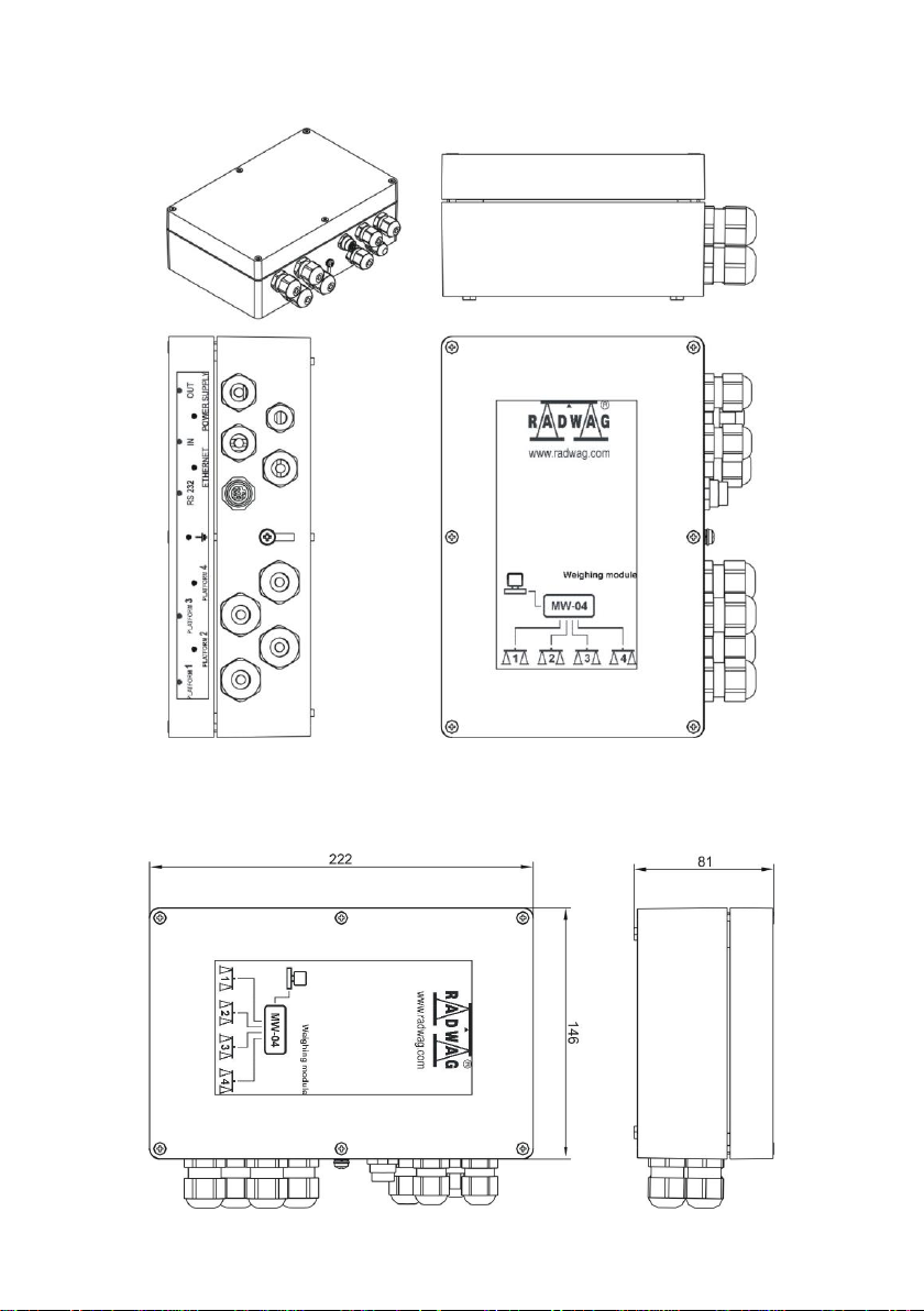
6. MECHANICAL DESIGN.....................................................................................................................................6
6.1.General View................................................................................................................................................7
6.2.Dimensions...................................................................................................................................................7
6.3.Connectors...................................................................................................................................................8
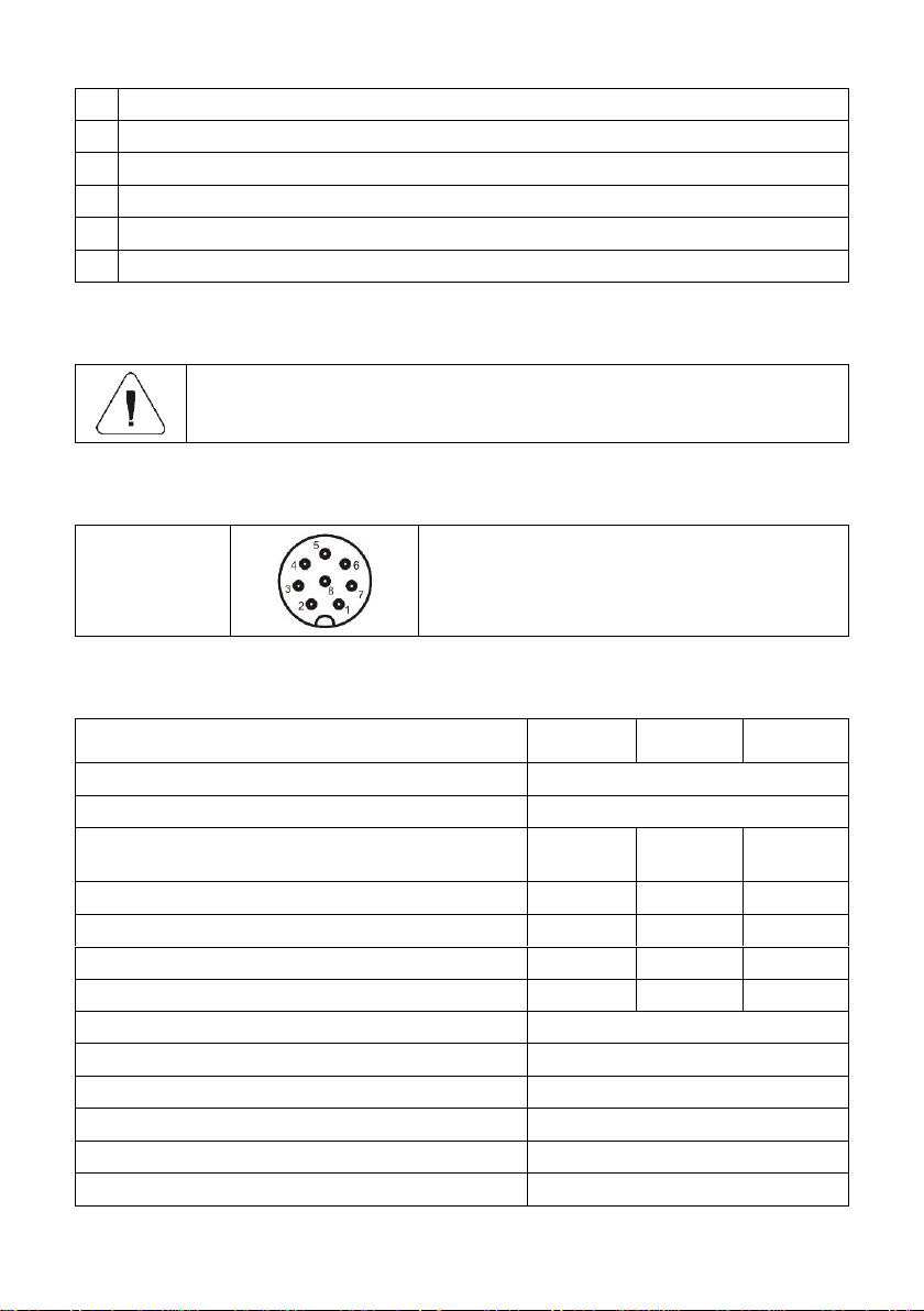
6.4.Pin Arrangement ..........................................................................................................................................9
6.4.1.RS232 Pins .......................................................................................................................................9
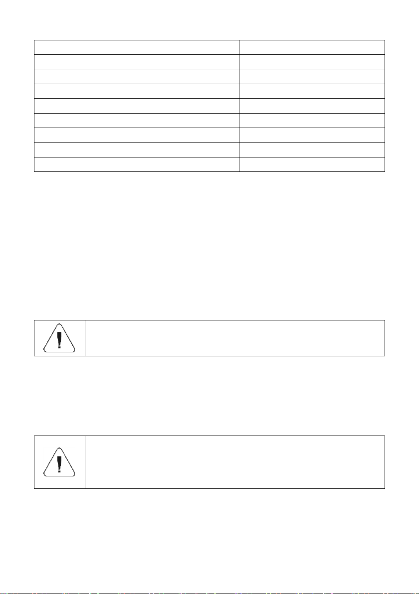
6.5.Technical Specifications...............................................................................................................................9
7. INSTALLATION................................................................................................................................................ 10
7.1.Unpacking and Installation.........................................................................................................................10
7.2.START-UP .................................................................................................................................................10
8. INSTALLER INSTRUCTION ............................................................................................................................11
8.1.6-Wire Load Cell Connection.....................................................................................................................11
8.2.4-Wire Load Cell Connection.....................................................................................................................12
8.3.Connecting Load Cell’s Cable Shield.........................................................................................................12
9. FACTORY PARAMETERS .............................................................................................................................. 13
9.1.Factory Parameter Access.........................................................................................................................13
9.2.Factory Parameters....................................................................................................................................14
9.3.Parameter Value Modification....................................................................................................................16
9.4.A/D Converter and Platform Configuration ................................................................................................16
9.5.Factory Adjustment ....................................................................................................................................16
9.5.1.Global Adjustment...........................................................................................................................16
9.5.2.Point Adjustment.............................................................................................................................17
9.5.3.Start Mass Determination................................................................................................................19
9.6.Gravitational Correction .............................................................................................................................20
9.7.Linearity Correction....................................................................................................................................20
10. EXTENSION MODULES................................................................................................................................21
10.1. 4IN//4OUT Module ...................................................................................................................................21
10.1.1. Technical Specifications...............................................................................................................21
10.1.2. Schematic Diagrams.....................................................................................................................22
10.1.3. Input / Output Signals ...................................................................................................................22
10.2. RS485 Module .........................................................................................................................................23
10.2.1. Signal Layout ................................................................................................................................23
10.2.2. RS485 Cable.................................................................................................................................23
10.3. PROFIBUS Module..................................................................................................................................23
10.3.1. Pin Arrangement...........................................................................................................................24
10.3.2. Interfaces Board with PROFIBUS Module Installed.....................................................................24
11. DIAGRAMS OF CONNECTION CABLES.....................................................................................................25
12. ERROR MESSAGES .....................................................................................................................................26

5
1.INTENDED USE
The MW-04 mass converter is designed to be a component of an industrial
load cell scale. Depending on the needs, communication with the mass
converter can be carried out via the following communication interfaces:
RS232, RS485, Ethernet, Profibus, and Modbus protocol. The MW-04 mass
converter can connect with PUE 5.15, PUE 5.19, indicators or a PC.
Operation of the MW-04 mass converter via PC is carried out using
MwManager software. For more information on the MwManager software read
MwManager manual.
2.WARRANTY CONDITIONS
A. RADWAG is obliged to repair or exchange all elements that appear to be
faulty by production or by construction.
B. Defining defects of unclear origin and means of their elimination can only
be realized with the assistance of the manufacturer and the user
representatives.
C. RADWAG does not bear any responsibility for damage or losses
resulting from unauthorized or inadequate performing of production or
service processes.
D. The warranty does not cover:
mechanical damage caused by product exploitation other than
intended, damage of thermal and chemical origin, damage caused by
lightning, overvoltage in the power network or other random event,
inappropriate cleaning habits.
E. Loss of warranty takes place if:
a repair is carried out outside RADWAG authorized service point,
service claims intrusion into mechanical or electronic construction by
unauthorized people,
the device does not bear security seal stickers.
F. Warranty conditions outline the warranty period for rechargeable
batteries attached to the device for 12 months.
G. For detailed warranty conditions read the service card.
H. Contact with the central authorized service: +48 (48) 386 63 30.
3.MAINTENANCE
In order to clean the weighing instrument risk-free, it is necessary to disconnect
the device from the mains.
Avoid using cleansers containing any corrosive chemicals, e.g. bleach
(with chlorine). Do not use cleansers containing abrasive substances. Always
remove the dirt using microfiber cloth to avoid damage of protective coating.

6
In the case of a daily maintenance:
1. Remove the dirt using cloth dipped in warm water.
2. For best results, add a little bit of dishwashing detergent.
4. SERVICE AND REPAIR
In the case of any sign of damage, it is necessary
to disconnect the device form the mains immediately.
The damaged component must be replaced or repaired by
RADWAG service directly.
In the case of any problems with correct operation of the device, contact the
closest manufacturer's service point.
In the case of defects, deliver the faulty product to the manufacturer's service
point. If the product cannot be delivered to the manufacturer's service point, call
the service and report the defect. Repair scope and method will be set up.
The user is NOT ALLOWED to carry out any kind of repair
of the device himself/herself. Any attempt of module
modification, repair etc., by unauthorized persons, will result
with loss of validity of manufacturer-issued certificates,
declarations and warranty.
5. RECYCLING
MW-04 mass converters must be recycled, they are not to be treated as a
regular household waste. Devices to be decommissioned must be
decommissioned in accordance with valid legal regulations.
6.MECHANICAL DESIGN
The MW-04 mass converter is equipped with metal housing. Signal cables are
fed through cable glands. Communication with peripheral devices is carried out
via one of the following communication interfaces: RS232, RS485, Ethernet,
Profibus. MW-04 converter is equipped with 4 optoisolated inputs and 4 Opto
MOS outputs. It is powered with 100÷-240 VDC voltage.

7
6.1. General View
MW-04 mass converter, general view
6.2. Dimensions

8
MW-04 mass converter, dimensions
6.3. Connectors
Arrangement of MW-04 mass converter's connectors
1
PG11 cable gland for platform 1.
2
PG11 cable gland for platform 2.
3
PG11 cable gland for platform 3.

9
4
PG11 cable gland for platform 4.
5
M12 8P connector for RS232.
6
M16 cable gland for Ethernet/RS485 cable (conditioned by the converter model).
7
M16 cable gland for 4IN cable (or PROFIBUS IN connector).
8
M12 cable gland for power cord 230VAC.
9
M16 cable gland for 4IN cable (or PROFIBUS OUT connector).
6.4. Pin Arrangement
Pin arrangement (signals) for 4IN/4OUT, RS485, PROFIBUS
modules is to be found in section 10 of this manual.
6.4.1. RS232 Pins
RS232
Pin2 –RxD
Pin3 –TxD
Pin5 –GND
6.5. Technical Specifications
MODEL
MW-04-1
MW-04-2
MW-04-3
Standard platform qty
2
Maximum platform qty
4
Communication interface
RS232,
Ethernet
RS232,
RS485
RS232
PROFIBUS
4IN/4OUT module*
1
1
-
RS485 module
-
1
-
PROFIBUS module*
-
-
1
DP-5 platform module
2
2
2
Housing
Aluminium
Ingress protection
IP65
Power supply
100 ÷ 240 VAC 50 ÷ 60 Hz
Power consumption
25 W
Operating temperature range
-10 °C ÷ 40 °C
OIML class
III

10
Verification units
6000
Maximum input signal gain
19.5 mV
Maximum converter division qty
8388608
Maximum voltage per verification unit
3.25 uV
Minimum voltage per verification unit
0.4 uV
Minimum Ioad cell impedance
80
Maximum load cell impedance
1200
Load cell excitation voltage
5 V
Load cell connection
4 or 6 wires
*) - PROFIBUS and 4IN/4OUT modules are mounted interchangeably (the device is equipped
with one of them only).
7. INSTALLATION
7.1. Unpacking and Installation
A. Take the mass converter out of the packaging.
B. Connect the weighing platform to the mass converter, next place the
weighing device on a flat and even surface. Keep it away from any
sources of heat.
C. Level the device.
Levelling procedure is to be found in 'TWM4 Scale' user
manual.
7.2. START-UP
Plug the power cord to the mains.
Wait for connection to be established between the mass converter and the
„MwManager” software, read the weighing result.
The procedure of communication establishing and a detailed
description of connection between the MW-04 mass
converter and the ‘MwManager’software is to be found in
the ‘MwManager’ user manual.

11
8.INSTALLER INSTRUCTION
The MW-04 mass converter can be a base component of a load cell scale.
Maximum quantity of installed A/D converters in MW-04 mass converter is
4 pcs. Parameters of all converters are identical.
A/D converter board
8.1. 6-Wire Load Cell Connection
Connect 6-wire load cell to the main board following the diagram below:
6-wire load cell connection
Connection
Load cell signal
REMARKS
E
SHIELD
Refer to section 8.3
REF+
SENSE +
JP1 not to be soldered
REF-
SENSE -
JP2 not to be soldered
IN+
OUTPUT+
IN-
OUTPUT-
+EXC
INPUT+
-EXC
INPUT-

12
8.2. 4-Wire Load Cell Connection
Connect 4-wire load cell to the main board following the diagram below:
4-wire load cell connection
Connection
Load cell signal
REMARKS
E
SHIELD
Refer to section 8.3
REF+
-
Connect to +5V
REF-
-
Connect to AGND
IN+
OUTPUT+
IN-
OUTPUT-
+EXC
INPUT+
-EXC
INPUT-
8.3. Connecting Load Cell’s Cable Shield
Scale with a mass converter in
a metal housing connected with
a platform via a load-cell signal
cable.
Scale of compact mechanical
design, mass converter in a metal
housing connected with a platform
via an extension arm, etc.
Platform w/o galvanic
connection of the signal
cable shield.
POINT A, B
E
Platform with galvanic
connection of the signal
cable shield.
POINT A, B
POINT A, B
Point A, B –electrical connection with the housing.
E–solder pad on A/D converter board.

13
9.FACTORY PARAMETERS
In order to be able to edit and save factory parameters to the MW-04 mass
converter's memory, it is necessary to put a jumper allowing access to the
factory parameters.
9.1. Factory Parameter Access
Plug the power cord to the mains.
Press SW1 switch on the electronics board.
Factory parameters' access switch
Wait for connection to be established between the mass converter and the
„MwManager” software, go to <Parameters / Factory parameters>
submenu.
Factory parameters are set into groups: Adjustment, Weighing,
Information, Converter. To access a given group, select a respective tab.

14
Factory parameter window
In the case of few weighing platforms, the parameters are
displayed and edited for the platform which is currently
selected in the weighing result window (marked green).
<Converter rate> parameter is an exception, this parameter
is set globally for all available converters.
9.2. Factory Parameters
NAME
DEFAULT
VALUES
REMARKS
Adjustment
-
-
-
Range
3,009
-
Maximum range + 9e overload.
Range 2 threshold
0
-
Switching point of range II. For single
range balances set 0.
Range 3 threshold
0
-
Switching point of range III. For I-range
or II-range scales set 0value.
Reading unit: range 1
0.001
0.001 50
Rounding of the last digit and position
of a decimal point for weighing range I.
Reading unit: range 2
0.001
0.001 50
Rounding of the last digit and position
of a decimal point for weighing range II.
Reading unit: range 3
0.001
0.001 50
Rounding of the last digit and position
of a decimal point for weighing range III.

15
Adjustment weight
3
-
Adjustment weight mass.
Adjustment unit
kg
g, kg, lb
Adjustment (calibration) unit.
Verified
NO
YES - NO
Declaring whether the scale is verified
or not. YES - verified scale, NO - non-
verified scale.
Determine start mass
-
-
Start mass determination (refer to
section 9.5.3).
Global adjustment
-
-
Global adjustment (calibration) process
(read section 9.5.1).
Point adjustment
-
-
Point adjustment (calibration) process
(read section 9.5.2).
Set default
-
-
Restoring default adjustment parameter
settings of the active platform.
Weighing
-
-
-
Autozero range
0.25
0.1 ÷ 5
Autozero range (in divisions).
Stability range
1
0.1 ÷ 5
Stability range in [d] units.
Stability time
0.8
0.1 ÷ 5
Stability time, given in seconds.
Start mass control
1
0, 1, 2
Start mass control: 0–disabled, 1–
range: from -5% to +15% of start mass,
2–range: from -20% to +20% of start
mass.
Information
-
-
-
A/D divisions
-
-
Current quantity of converter divisions.
Adjustment factor
100
-
Adjustment/calibration factor.
Correction factor
1
-
Correction factor value
Start mass
100
-
Start mass value (in divisions).
Gcor
1
-
Gravitational correction factor (refer to
section 9.6).
Serial number
-
-
Serial number of the mass converter.
Adjustment qty counter
-
-
The quantity of factory parameter
recordings.
Extension module
4I4O
4I4O, 2I6O,
8I8O, Profibus
Installed extension module support:
4I4O –4 inputs / 4 outputs module;
2I6O –2 inputs / 6 outputs module;
8I8O –8 inputs / 8 outputs module;
Profibus –Profibus module.
Converter
-
-
-
Converter rate
10
10, 80
Converter rate change.
A/D converter and
platform configuration
-
-
Configuration of A/D converters and
platforms (read section 9.4).

16
9.3. Parameter Value Modification
Select a parameter, enter/modify its value.
Press <Save> button, Message <Save parameters?> is displayed.
Press <Yes> button to confirm, message <Changes saved> is displayed.
Press <OK> button to confirm.
9.4. A/D Converter and Platform Configuration
MW-04 mass converter can connect with 4 A/D converters. The used
converters and weighing platforms can be freely combined, and as a result give
many platform-converter variants. Devices to be constructed:
1-platform –multi-converter scale.
Multiplatform –1-converter scale.
Any configuration (mixed).
In order to configure platforms and A/D converters, enter <Parameters /
Factory parameters / Converter> submenu.
Procedure:
Configure converters and weighing platforms, to do it tick the right option.
In the case of an attempt to assign one converter to more
than one weighing platform, the following message is
displayed: <Converter is already in use>. Press <OK> button
to confirm and make a right choice.
Upon correct reconfiguration press <Save> button, message <Save
parameters?> is displayed.
Press <Yes> button to confirm, message <Changes saved> is displayed.
Press <OK> button to confirm.
9.5. Factory Adjustment
The MW-04 mass converter offers two methods of determination of adjustment
factor: global adjustment and point adjustment.
9.5.1. Global Adjustment
Global adjustment is carried out concurrently for all used A/D converters.
Determined values of correction factors are the same for each converter, they
equal 1. Global adjustment is intended for 1-load-cell devices (platforms), with
one A/D converter.

17
Procedure:
Go to the weighing result window, select a respective platform number.
Unload the weighing pan.
Press <Global adjustment> button, the following message is displayed:
Load the weighing pan with weight of specified mass value and press
<OK> button.
Upon completion, message <Adjustment factor determination
completed successfully> is displayed.
Press <OK> button to confirm.
Press <Save> button, message <Save parameters?> is displayed.
Press <Yes> button to confirm, message <Changes saved> is displayed.
Press <Yes> button to confirm. Determined adjustment factor, for the
currently selected platform, gets saved to mass converter's memory.
9.5.2. Point Adjustment
Point adjustment is carried out separately for every single used A/D converter.
Determined values of correction factors may differ for each converter.
Point adjustment is intended for multi-load-cell devices (platforms), where each
load cell is connected to a different A/D converter. This method ensures
automatic calculation of correction factor for each A/D converter, providing
correct scale eccentricity.
Example of correction factors, determined in the course of point adjustment.
Adjustment factor determination is performed for a currently
selected platform.

18
Procedure:
Go to the weighing result window, select a respective platform number.
Unload the weighing pan.
Press <Point adjustment> button, the following message is displayed:
Load the weighing pan with a weight of the specified mass value, make
sure that the weight loads the first A/D converter (1).
Press <OK> button, the following message is displayed:
Load the weighing pan with a weight of the specified mass value, make
sure that the weight loads the second A/D converter (2).
Press <OK> button, the following message is displayed:
Load the weighing pan with a weight of the specified mass value, make
sure that the weight loads the third A/D converter (3).
Press <OK> button, the following message is displayed:

19
Load the weighing pan with a weight of the specified mass value, make
sure that the weight loads the fourth A/D converter (4).
Press <OK> button,
Upon completion, message <Adjustment factor determination
completed successfully> is displayed.
Press <OK> button to confirm.
Press <Save> button, message <Save parameters?> is displayed.
Press <Yes> button to confirm, message: <Changes saved> is displayed.
Press <Yes> button to confirm. Determined adjustment factor, for the
currently selected platform, gets saved to mass converter's memory.
Upon completed point adjustment it is necessary to readjust
the start mass.
9.5.3. Start Mass Determination
Go to the weighing result window, select a given weighing platform
number.
Unload the weighing pan.
Go to <Adjustment> tab, press <Determine start mass> button,
message <Unload the pan> is displayed.
Press <OK.> button to confirm, start mass adjustment begins.
Upon completion, message <Start mass determination completed
successfully> is displayed.
Press <OK> button to confirm.
Press <Save> button, message <Save parameters?> is displayed.
Press <Yes> button to confirm, message: <Changes saved> is displayed.
Press <Yes> button to confirm. Determined start mass, for the currently
selected platform, gets saved to mass converter's memory.
Start mass determination is performed for a currently
selected platform.

20
9.6. Gravitational Correction
The function of gravitational correction compensates changes of earth gravity
being a result of different latitude and longitude. It enables correct calibration
of the weighing device away from the place of use. The gravitational correction
value must be entered with reference to tables prepared by „Radwag Balances
and Scales” or calculated using the below formula:
kal.
uzyt.
g
g
Gcor
Correction value ranges between 0.90000 ÷ 1.99999.
If the scale is calibrated at the place of use then the
gravitational correction value (<g-cor.> parameter) is 1.00000.
If the scale is calibrated away from the place of use
(longitudinal change) the value of <g-cor.> parameter must be
corrected.
9.7. Linearity Correction
„Linearity” tab enables access to thresholds and linearity deviations
of a currently selected platform.
Linearity correction window
Other manuals for MW-04
1
This manual suits for next models
3
Table of contents
Other RADWAG Media Converter manuals