Rainbow DPA 1.2500 User manual

Installation instruction for
Digital Line Amplifier
DPA 1.2500 Subwoofer Amplifier 1 x 2500 watt art.no.: 271023
Please read carefully the installation instructions before you start installing the amplifier!
Audio Teile Team GmbH - P.O. Box 1225 – 74899 Bad Rappenau
Phone + 49 / 7264 – 9136-0, Fax + 49 / 7264-9163-50
1

Technical specifications DPA 1.2500
• Digital power amplifier (class D) with integrated peak current MOSFET switch-mode power
supply.
• Double amplifier output for double voice coil-subwoofer, 1 Ωstable.
• Amplification with very low noise.
• Pre-amplification input dissymmetrical used for optimum interference suppression.
• Additional pre-amplification output „Line Out“ for active crossover or additional amplifier.
• Input level control „Level“ infinitely adjustable.
• Sub Level Control infinitely adjustable through cable remote control.
• Active crossover, low-pass, 35 Hz – 250 Hz 24 dB/oct. on/off switch.
• Active crossover, subsonic 15 Hz – 35 Hz 18 dB/oct. on/off switch.
• Bass boost at 45 Hz, up to + 18 dB infinitely adjustable.
• Reversible disconnection cut off with thermal protection.
• Disconnection cut-out at d.c. for speakers.
• Disconnection cut-out at speaker short circuit and speaker under-impedance
• Protect and Overload display with red and yellow LED.
• Gold-plated fuse carrier with 80 A fuse, replaceable from outside.
• Soft start remote muting to suppress switch-on peaks.
• Low power requirement for remote muting circuit.
• Conforming to standard gold-plated power connection up to 35 mm² and speaker connection
up to 10 mm².
• High-tech assembly in semi-SMD design with low coupling bar function.
• Noise immune due to homologation with officially approved new „e“ standard and
CE certificate.
Technical dates DPA 1.2500
Peak load 1 x 2500 watt
Output 1 x 560 watt rms on 4 Ω
Output 1 x 750 watt rms on 2 Ω
Output 1 x 1200 watt rms on 1 Ω
Total harmonic distortion 0,04 % (1kHz / 1 watt)
Signal-to-noise ratio >80 dB / A-assessment
Transmission range – 3 dB 10 Hz – 500 Hz
Input sensitivity Line Input 200 mV – 6 V
Input impedance Line Input 22 kΩ
Connection impedance 1 Ω, 2 Ωor 4 Ωpossible
Attenuation constant >500 on 4 Ω
Operating voltage 11 V – 16 V DC
Power consumption max./ Impulse power consumption 95 A / 200 A
Efficiency 91 % at 13.8 V DC
Short-circuit fuse – overload immediate disconnection
Temperature monitoring cooler 85 °C disconnection
Soft start muting on/off 2s switch-on delay
Dimensions: b x h x d 382 x 226 x 54 mm
Weight 5,0 kg
Approval number e13 and CE
Active controls:
Low-pass 35 Hz – 250 Hz infinitely adjustable, 24 dB dB/oct.
Subsonic filter 15 Hz – 35 Hz infinitely adjustable, 18 dB/oct.B
Bass boost 45 Hz, up to + 18 dB infinitely adjustable
2

Front view and operating elements DPA 1.2500
Picture 1:
1 = Input jacks stereo „Line Input“ for the signal input from the CD-radio.
2 = Output jacks stereo „Line Out“ for additional amplifier.
3 = Controller „Level“ for the adjustment of the input sensitivity of „Line Input“.
4 = Controller „Bass Boost“ for the bass boost of the subwoofer at 45 Hz from 0 dB up to + 18 dB.
5 = Frequency regulation of the low-pass, infinitely adjustable from 35 Hz up to 250 Hz.
6 = Frequency regulation of the Subsonic filter, infinitely adjustable from 15 Hz up to 35 Hz.
7 = Operational check: LED Power, amplifier in operation.
8 = Operational check: LED Protect (see description).
9 = Operational check: LED Overload (see description).
10 = Connecting jack for the Sub Level remote control (cable and remote control are included).
11 = Power connection (+) plus „+12V“, use only with fuse.
11 = Power connection (-) minus „GND“, car body or central mass point.
12 = Remote connection „REM“ for the switch-on muting of the CD-radio.
13 = Loudspeaker connection mono (intern parallel switched!).
14 = Fuse 80 A according to DIN-norm, replaceable from outside.
3

Installation DPA 1.2500
Install the amplifier on a suitable, well-aerated place in the vehicle possibly on the Chassis sheet
metal with the included sheet metal screws.
The heating of the amplifier can reach a very high surface temperature. Enough space to high
temperature sensible elements is absolutely necessary.
Attention: Disconnect the minus pole of the battery before you start with the installation work.
Our products are only suitable for users with the necessary professional installation
knowledge and can only be carried out very carefully according to the relevant safety
regulations.
Before the connection of the power supply- and loudspeaker cables you have to unwind and remove
to the top all hexagon bolts on the amplifier connecting side with the included hexagon spanners in
order that the screws will not hinder the insertion of the cables. Don’t screw them out entirely!
Attention: Important safety notice.
The unwinding or screwing down of the hexagon screws on the amplifier connecting side during
active operation of the amplifier (amplifier is alive) is not allowed, as a short cut from the hexagon
spanner to the heating cannot be excluded, which could result in a damage of the amplifier and
vehicle, as well as burns due to the high short cut voltage on the spanner.
The opening by boring of the amplifier connection side, in order to enlarge the cross section for
cable input will lead to the destruction of the electronics and to the immediate loss of all guarantee
claims.
Connect the red cable with a diameter of 25 mm² to 35 mm² directly to the positive pole (+) of the
battery or to the central positive point of the Hifi-system and lay the cable to the amplifier. Be
absolutely sure that the main current cable of a central positive point has been protected by xxA fuse
(see below).
Provide the free end of the current cable with an end splice and insert in one of the two free clamps
of the included fuse carriers (with 80 A fuse). Take off the cross section reduction of the clamp if
necessary. Drive in the clamp screws with the included hexagon spanner.
Connect the black cable with a diameter of 25 mm² to 35 mm² directly to the car body or on the
central mass point of the hifi system and lay the cable to the amplifier.
Provide the free end of the current cable with an end splice and insert into the clamp „GND“ (11) of
the amplifier. Drive in the clamp screw with the included hexagon spanner.
The xxA fuse must be proportional for the overall power of the complete audio system. Therefore the
overall power of all appliances must be considered. Check the manufacturer indications on the used
appliances and determine the current consumption by adding (if necessary then add the fuses with
indication of Ampere). The resulting total is the overall power in Ampere and will be transmitted to
the included fuse. It is absolutely necessary that the fuse will be put in the mainstream cable behind
the battery (+).
4

Remote Connection DPA 1.2500
Lay the cable with small diameter from the car-radio- or CD-player-Remote clamp to the amplifier
and fix onto the amplifier connection „REM“ (12) using an end splice.
When switching on- or off the car-radio/CD-player, the amplifier will be switched on- or off with a
time-invariant of 2 seconds by a soft muting.
Switching-on- / Functioning control by LED DPA 1.2500
The turn-on of the amplifier will be indicated by a „Power“ LED (7). The amplifier will be switched-
on with a time-invariant of 2 seconds. Due to this soft start, an uncontrolled excursion of the
loudspeakers will be omitted when switching on the amplifier.
In case of a critical impedance below 1 Ωor a complex burden, short cut on the loudspeaker outputs,
direct current on the loudspeaker voice coils, as well as the overstressing with too high heating
temperatures, the monitoring electronic will switch off the amplifier immediately.
If the „protect“ LED (8) is lighted up than switch off the amplifier and check the system on above-
mentioned errors. If the amplifier has been switched off due to too high heating temperature than the
„protect“ LED will not be lighted up!
In case of an overstressing of the amplifier the „overload“ LED (9) will blink in a 3 second interval.
Please switch off the amplifier and check the system for errors. In addition you make with the help of
the „overload“ LED a self-test of the amplifier during switching on. The LED should light up when
switching on the amplifier and switch off after 3 seconds.
After the repair of the failures or after the cooling period due to overheating you can activate the
amplifier again by switching it on-/off.
A numerous switch off of the amplifier due to overheating is indicating a wrong installation place of
the amplifier, which should be changed by a well-aerated place. In case of a permanent failure
indication the system will be defect, please send in the amplifier for inspection.
Connection „Line Input“: Pre-amplifier-input DPA 1.2500
The output signal of the car-radio/CD-player will be fed on the chinch jack „Line Input“ (1) R (right)
and L (left) with chinch cables. The input level will be controlled by the potentiometer „Level“ (3)
from 200 volt (max.) to 6 volt (min.). The input needs the smallest input voltage of 200 m volt at
right limit stop (max.) of the potentiometer „Level“.
The jacks (1) of the amplifier must always obtain a right and left signal. Only with a signal input at
the same time to the right and left chinch jacks the complete mono power will be played.
If only one mono signal is available, e.g. when operating with an active crossover with only one sub-
extension, then the jacks (1) must be provided with an Y-chinch adapter.
Attention: When using chinch cables with different length than a potential difference could be the
result. Due to this difference in length a zero potential will be formed, which causes unpleasant
interferences in the lighting dynamo.
Don’t lay chinch cables parallel to current cables, in order to prevent interferences.
5

Picture 2: Connection of the amplifier with chinch cables.
Connection of the loudspeaker DPA 1.2500
The subwoofer will be connected to the connecting terminal „SP“ (13), which are clearly marked
with + and -. Please provide before connection the endings of cables with end splices. The use of a
minimum cable diameter of 4 mm² to 10 mm² enables the necessary low impedance with little
potential drop; the excellent attenuation factor of the amplifier will be remained during almost the
complete frequency response. When connecting the subwoofer to the amplifier it is absolutely
necessary to provide the same polarity/in phasing. In case you mix up the polarity / phases, than the
woofer reproduction will get lost due to phase delete.
Attention: The amplifier can only be operated mono; the two supply terminals are connected
parallel intern. Therefore the amplifier can also not be operated with a bridge circuit!
The loudspeaker connections must not attach to the car body. In case of non-observance, the
amplifier may be damaged.
The connecting impedance of the subwoofer must in case of connection of both supply terminals not
be below 2 Ω, in order not to remain under the critical 1 Ωlimit. A 1 Ωloudspeaker connection is
due to thermal limit of current loading capacity not allowed.
6

The reason is that the amplifier is not equipped for „HCC-High-Current“ type (full-load amplifier),
which can activate over dimensional power reserve capacities on very small impedances < 0,5 Ω.The
semiconductors are not dimensioned enough for this operational case.
Notice: A 4 Ωloudspeaker impedance on each of both clamps presents for the amplifier only a real
end resistor of 2 Ω. In case of 2 Ωeach it will be only 1 Ωand in case of 1 Ωit will be only 0,5 Ω.
This impedance dividing is the result of the parallel switching of the connecting clamps.
Picture 3: Connection of one or two subwoofers. In case of subwoofers with double voice coils, you
can use one connecting clamp each for the voice coils.
Adjustment of the „subwoofer“ DPA 1.2500
Low Pass:
This operation mode is only used for the operation of subwoofers. The internal active crossover will
only pass according to the installations of the potentiometer „Low Pass“ (5), up to 250 Hz at 24 dB
slope per octave. A low slope frequency (80 Hz) has the advantage that the subwoofer which is
mostly placed in the boost cannot be located anymore and will seem to be at the front in the total
acoustic pattern.
Bass Boost:
For vehicles with a strong absorbing woofer reproduction, it can be optimised with the potentiometer
„Bass Boost“ (4) at 45 Hz up to + 18 dB. Adjust the woofer reproduction according to the insertion
and the acoustic. The correct adjustment is achieved, if the woofer reproduction is full and dry. A too
strong woofer accentuation will lead in case of high loudness to the overstressing of the subwoofer!
+ 6dB corresponds to 4 times of the amplifier power and will lead to an unnatural acoustic pattern.
7

Subsonic:
The intern subsonic filter deregulates the subwoofer and amplifier from all frequencies below the
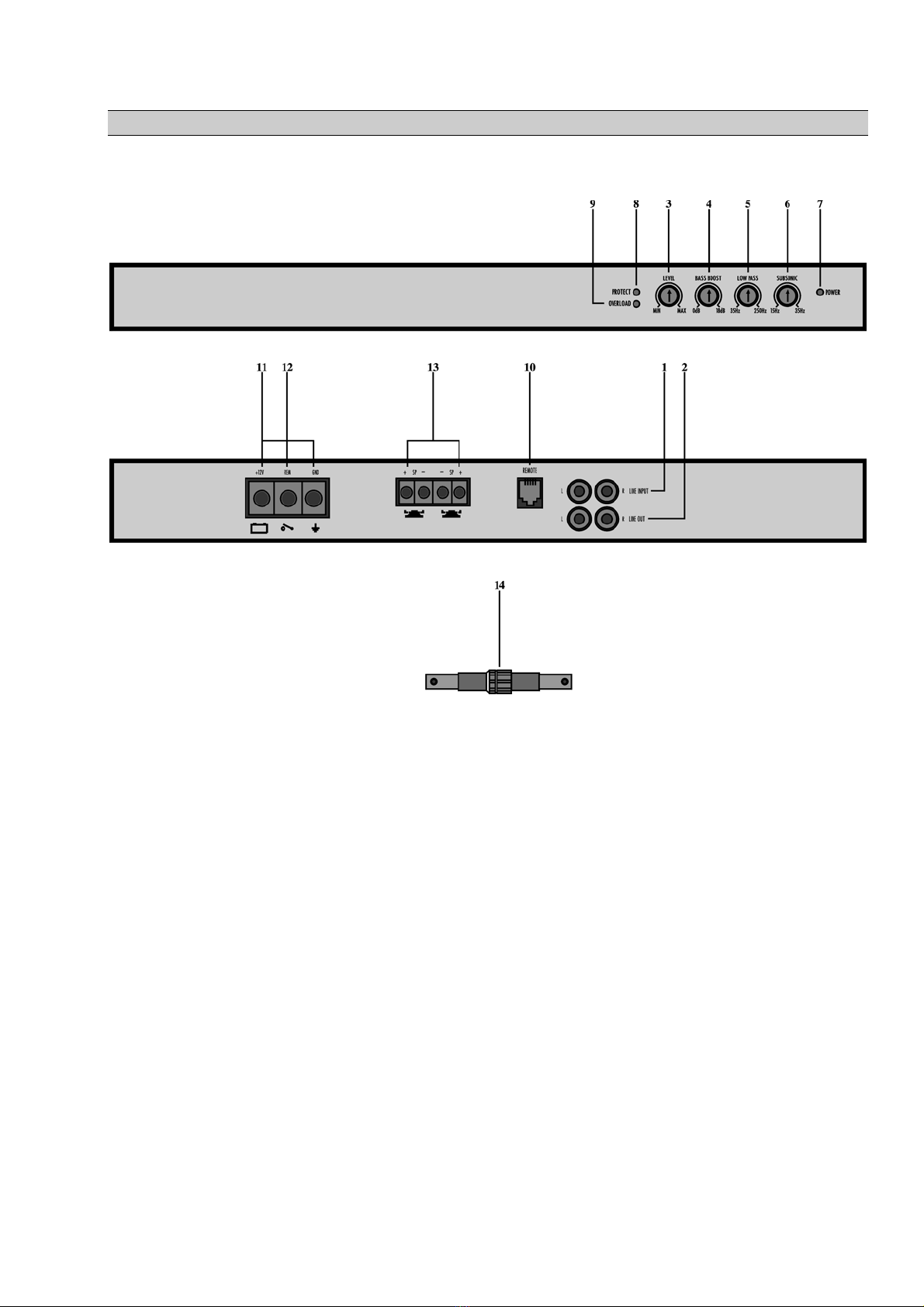
potentiometer „Subsonic“ (6) adjusted frequencies (15 Hz up to 35 Hz at 18 dB slope per octave).
This enables that the frequencies which cannot be reproduced by the woofer will be kept away which
ensures an unnecessary stress of the subwoofer and amplifier.
Subwoofer-adjustment DPA 1.2500
In order to find the correct adjustment of the loudness, dividing frequency and the phase position,
you should have much time, patience, know-how and your favourite CD.
In the first step you have to locate the installation place of the subwoofer. The preferred boot corners
and close to the dividing wall situated positions on the boot floor will only slightly increase the
electron beam resistance. Therefore the expected increase of the efficiency and an improve of the
dynamics for the desired 3 dB cannot be completely achieved.
The adjustment of the Dividing frequency, phase position and the loudness level is only relevant for
the stipulated installation place. All adjustments should only be optimised by the user only when the
front and rear systems are operating. The single operation of the subwoofer without front- or rear
system is not advisable and will lead to the mismatching of the level, the dividing frequency and the
phase position.
Adjustment of the dividing frequency:
The dividing frequency of the subwoofer must be matching to the dividing frequency of the front-
and rear system. Will the front- and rear systems get a 80 Hz high-pass signal, than the dividing
frequency of the subwoofer should be matched to the high-pass frequency. But the dividing
frequency should not be essentially higher. A maximum of 80 Hz – 100 Hz are advisable, in order
that the locating of the subwoofer can be excluded and a clean roll-off at 80 Hz – 3 dB at both
dividing frequencies can be guaranteed.
Adjustment of the phase position:
The relative phase position between subwoofer and the front- and rear systems is relatively
independent to the dividing frequency of the subwoofer. It is advisable to find for the second step the
correct and optimal phase position of the subwoofer to the front- and rear systems. This results in the
correct adjustment and in case of correct polarity from the summing up of the sonic part of the
subwoofer and the front- and rear systems and can be recognized by a more dry and voluminous
bass. In case of a incorrect or wrong polarity of the subwoofer or the front- and rear system, a
subtraction of the sonic parts which can be recognized by a weak level and a mat bass. The amplifier
DPA 1.2500 has no phase invert circuit. The adjustment of the phase can be effected through a
change of the poles of the loudspeaker cables on the subwoofer (+ to – and – to +).
Adjustment of the loudness level:
The last step is the adjustment of the loudness of the subwoofer to the front- and rear systems. Adjust
the level controller of the front- and rear system in order that together with the fader of the car-radio
an optimum loudness can be guaranteed. Switch the front- and rear system with a title of your
favourite CD on medium loudness. Adjust the subwoofer loudness on the level controller of the
amplifier to silent (minimum loudness), not on the radio. Then adjust the level controller of the
subwoofer while music is playing and increase the volume slowly until the subwoofer will be
pointed out of the acoustic pattern. Then reduce the subwoofer loudness with the level controller
until the subwoofer will just not point out from the acoustic pattern anymore. Don’t change the level
controller of the subwoofer anymore.
8

Notice for current supply DPA 1.2500
In order to avoid potential differences and disturbances, it has to be guaranteed that the minus line (-)
has the same cable diameter as the positive line (+). The car body is due to the high potential
differences not suitable as minus pole for this use.
In order to avoid interferences all audio-systems must be put on a central mass point, which will be
determined according to each vehicle type with the testing during installation. A direct connection to
the minus pole (-) of the battery is due to interference reasons not always advisable. Choose motor
unit or search interference minimum on the car body and provide all components from this point
with the minus line (-) (use distributing cabinet).
The same criteria are relevant for the positive pole (+). In order to prevent disturbances you have to
put the battery line onto a distributing cabinet. From this point all audio-components (including radio
and CD-player) as well as all memory lines will be provided with current.
In case the positive line (+) has to be filtered due to interference suppression reasons, than you can
only use a filter choke with the corresponding total loading capacity for the main current line (+),
(Consider total current of all components). Additional filters in the individual component positive
inputs will only worsen the interference suppression.
In case of high reproduction loudness, in particular in the woofer area, the amplifier may clip early
due to the potential difference on the long cable line. This can be prevented through a high cable
diameter and a minimizing of the transition resistance on the inputs. Corresponding precautions can
be taken with minimize loosing battery terminals and distributing cabinets by the first installation.
In case of insufficient cable diameter or high current consumption in the impulse clipping of the
woofer reproduction as well as the active operation of several amplifiers, a better clipping can be
achieved with the help of an additional balancing capacitor. This capacitor will provide enough
currency in milliseconds due to its high capacity (~ 1 F / 40 V) and enables a supplement
interference suppression and smoothening of the distribution voltage and the currency. The
installation has to be effected directly onto the amplifier or on the distributing cabinet.
Indication of the „central mass point“ DPA 1.2500
1. Install and test the system completely.
2. Prepare the minus (-) connection of the audio system provisional on the car body-minus
(point 1). Install the equipotential bonding conductor in case it does not exist from the
generator body to point 1.
3. Switch on the system, put in an empty cassette or CD (0dB-Track) and put the loudness on
minimum.
4. Put on the motor and take into operation all consumers, also the light, electrical heating and
the blast. →In case you will hear whistling interruptions due to speeding up of the engine
which will in- or decrease with the speed in the frequency, than the mass connection has to be
corrected.
5. Plug off the antenna plug from the car radio. Has the interference disappeared than a potential
difference “antenna foot point to the battery” is existing.
9

→Remedy: Put electrical insulation filters into the antenna cable (Art.no.: 251001/251055).
If the interruption still didn’t appear then make the following:
6. Disconnect the minus line (-) of the audio system from point 1 and connect to the motor
block. →Check if the interference has been removed.
7. In case the motor block should not solve the interference, than you have to scan the car body
while the engine is running with minus line of the system as long as the interference has
removed drastically. →Lay bare this point (point 2) and free from underseal rests.
8. Fix screw with large diameter on this point. Polish the metal sheet around the screw and
protect with car body coating fat.
9. Fix all mass cables onto this screw or place the distributing cabinet and distribute to all
components (central mass point).
10. Remaining interferences can be removed with an LC-filter in the positive line.
The search for the central mass point can also be achieved by means of a millivoltmeter (lowest
potential drop) or by means of a milli ohmmeter (lowest resistor). Home position should always be
motor block or point 1.
The digital electronics in the vehicle area provides an unignorable interruption spectrum up to the
GHz area (interruption while radio reception and car telephone). The combinational circuit parts of
the amplifier, Digital tuner and CD-player contribute also to the current pollution. All these
interrupting spectrums can be found on the supplying lines and will be partly worked up.
The result is a roughness acoustic pattern with a fog on the tweeter area. The amplifiers will already
in the no load operation or in the smallest power range heated very high-by-high frequently
interrupting frequencies. The pre-amplifier of the amplifier cannot distinguish between music and
interrupting signal and amplifies everything according to its function, which is on the „Pre-In“ input
or on the current input. According to the manufacturer the best possible has been realized with the
amplifiers in order to attenuate such occurrences. This will be documented by the EEG-type
approval, which tests the amplifiers for irradiation disturbances and for self produced disturbances.
After the tests for EMV-limits have been passed, an e-number will be given. The frequency response
of the amplifiers should therefore for the stated reasons decline by at latest 30 kHz in order to
prevent an unnecessary heat up. At amplifiers in Class A or with pre-amplifiers in Class A, a heating
up will be unavoidable because of the higher static current also in a small volume range, which
should not be mixed up with the described interruption interferences.
The removing of the mentioned interferences can only be effected concertedly and requires already
for the installation of the system special knowledge in the field of interference elimination. In
addition you can find in the specialist literature and specialist publications convenient and practical
suggestions currently described. When observing the basic rules for cable installation, central mass
point and filtering of the current supply, a good screening can be provided when using quality
chinche cables. Special screening problems, which can occur according to each vehicle type
differently, must be removed from case to case by a specialist directly on the object.
10

Picture 5: Principle of the circuit diagram
Main fuse Equipotential bonding conductor generator body
Connection if needed
11

Important operational notice DPA 1.2500
The amplifier is provided for the use on a 12 V step-down system or for presentation purpose on a 12
– 14,3 V / 25 A power supply. The connection on another supply point is not allowed.
In case of a defect fuse, please replace only with the same type. Please pay attention for the
indications on the defect fuse. In case the new fuse should be defect again, than there might be an
error in the system. The opening of the amplifier for the change of components, piece parts or the
function, as well as the self repair is not allowed. In case of non-observance, the guarantee claims
will expire.
Due to safety technical reasons, you should only fix the amplifier with the included sheet metal
screws. In case of other fixing methods, we will not be held liable for.
Safety instructions for the user in order to prevent injuries and accidents:
The products are only suitable for users with the necessary installation knowledge. The relevant
safety regulations for bearing car body parts, instructions on the vehicle safety inside, as well as the
regulations of the competent vehicle manufacturer are necessary to be observed.
Guarantee regulations DPA 1.2500
With this user guarantee the Rainbow GmbH in Bad Rappanau guarantees on the product from the
date of the first purchase or the first installation by the authorised specialist dealer a 12 months
guarantee on material and manufacturing.
The guarantee is limited to the replacement of defective components, which have defect due to
construction- or material fault, as well as to the guarantee repair.
Accidents, acts of god or other causes, which Rainbow is not responsible for, in particular water and
fire are not included in the guarantee.
901133
Edition: MPJ/1.0 – 11/00
This installation instruction is copyrighted. Each duplication or reprinting, also part of it and each
reproduction of the pictures, also in a different version, is only permitted with a written allowance of the
Rainbow company.
Copyright © 2000 Rainbow GmbH. Rainbow is a registered Trademark.
12
This manual suits for next models
1
Table of contents
Other Rainbow Amplifier manuals