RainTracker RT-50A User manual

2. TEST THE EXISTING WIPER SYSTEM
Make sure that the existing wiper system works in off,
intermittent (if so equipped), slow, and fast modes of
operation, and that the wash motor works.
3. LOCATE THE
WIPER SYSTEM
PARTS
You will likely need to
remove access panels.
You can often trace wires
from the switch or motor,
or listen for clicking relays
when the wiper system is
in intermittent mode.
5. INSTALL THE RAIN TRACKER
INTERFACE MODULE
Make sure the location you select for the
module will not conflict with the
operation of any equipment, such as
accelerator or brake cables. Use the
wiring diagram as a guide in connecting
the Rain Tracker interface module into
the existing wiper system. See last
pages for tips on making connections.
5A. MAKE THE INTERFACE CONNECTIONS
Connect the wires as shown in the
diagram. If the diagram requires that you
make a chassis ground connection, find a
suitable metal frame member and screw,
and make sure that it is free of paint. Bad
grounds are the most common problems
we encounter when troubleshooting Rain
Tracker installations.
5B. PLUG IN THE INTERFACE MODULE
Plug in the interface connector so that its
locking ramp engages the locking ramp on
the interface module. The BLK ground wire
should be closest to the sensor Jack, J1.
DO NOT PLUG THE INTERFACE MODULE
CONNECTOR IN UPSIDE-DOWN.
Rain Tracker Model RT-50A Installation Manual - Page 1 of 4
DOCUMENT NUMBER 001-1125-001 A
The supplied round activation switch turns the Rain activation switch, drill a hole (5/8 inch or ¾ inch
Tracker on to default sensitivity. Mount the switch depending on switch model supplied) and file the
before you connect the switch wires to the Rain hole slightly larger until the switch can press in
Tracker. Select a mounting location in a dash appropriately. File a locating notch as needed.
knock-out panel, or in an under-dash panel Other styles of (SINGLE POLE) switches are
(available at auto parts store.) To mount the round available from Radio Shack and other suppliers.
1. GET A WIRING DIAGRAM FOR YOUR VEHICLE
Go to www.raintracker.com and click on “Compatibility.” Print out any
special installations wiring diagrams that pertain to your car or truck.
If the instructions refer to either the HSS or GSS diagrams included
with this manual, write your specific vehicle
wire colors on the diagram. If the
instructions call for external components,
they are usually included in the
accessory kit.
INSTALLATION INSTRUCTIONS
MODEL RT-50A
MODEL RT-50A RAIN SENSING WINDSHIELD WIPER CONTROL
6. INSTALL THE SENSOR
Select a coupler mounting location within the area swept by
the wipers, and out of the shadeband. Just below the mirror
mount is usually a good location. Tip: mark the location with a
piece of masking tape on the outside of the windshield, and
stand back from the vehicle to make sure the mark is level.
Prime the sensor mounting location with isopropyl alcohol.
Do not skip this step! Un-snap the coupler from the sensor.
Remove the red protective film
from the coupler, and rock the
coupler onto the windshield.
Snap the sensor into the
coupler.
7. INSTALL THE SENSOR
CABLE
Connect one end of the sensor
cable to the sensor, and route
the cable under the head liner
and down the vehicle's trim to
connect it to the interface
module.
8. SECURE THE
INTERFACE MODULE
Use cable ties to secure the
interface module to a bracket or
convenient location. Reinstall
access panels as needed.
9. TEST THE RAIN TRACKER SYSTEM WITH A SPRAY
BOTTLE OR GARDEN HOSE
Turn the ignition to accessory mode. Use the wiper control switch
to verify that all manual modes (off, slow, fast, and wash) work.
Put the system in Rain Tracker mode by turning on the activation
switch. Spray a light mist at the sensor and verify that the Rain
Tracker runs the wipers in intermittent mode. Spray more water
and confirm operation in steady slow and fast speeds.
SENSOR CABLE ROUTED
UNDER HEADLINER
SENSOR CABLE
BEHIND PLASTIC TRIM
SENSOR REARVIEW
MIRROR
SHADE-BAND
AREA SWEPT
BY WIPERS
TYPICAL RAIN TRACKER
INSTALLATION
RAIN TRACKER
INTERFACE MODULE
WIPER MOTOR
ASSEMBLY
WIRING
HARNESS
RAIN TRACKER
ACTIVATION SWITCH
EXISTING CONTROL MODULE,
BODY-COMPUTER, OR RELAY.
BUILT INTO SWITCH IN SOME CASES
4. MOUNT THE RAIN TRACKER ACTIVATION SWITCH
EXISTING
WIPER
SWITCH

/
OFF
INT
SLO
FAST
OFF
INT
SLO
FAST
+12V
TYPICAL EXISTING WIPER
CONTROL SYSTEM
WASH
CUT
CAM
+12V
+12V
INT
RELAY SLOW
FAST
FAST
+12V
BUTT-SPLICE
CONNECTION
BUTT-SPLICE
CONNECTION
1
2
3
4
5
678 SENSOR
CON. J1
MODEL RT-50A
SENSOR
B+ GND
/
MODE
READER
SLOW
RELAY
(+12V)
BLK
RED
PPL
ORN
PNK
GRY
WHT
YEL
GRN
BLU
RAIN TRACKER
ACTIVATION SWITCH
910
SNC
SNO
SC
RI
RO
FAST1
FAST2
/
FAST
RELAY
MOUNT THE SWITCH
BEFORE YOU WIRE TO IT!
GROUND
WASH
CAM
WIPER
MOTOR
GROUND
PARK
RUN
SLOW
GROUND
WASH
MOTOR
MOTOR
COMMON
TERMINAL
RAIN TRACKER RT-50A IN HOT-SIDE SWITCHING APPLICATIONS (MOST COMMON)
/
OFF
INT
SLO
FAST
OFF
INT
SLO
FAST
TYPICAL EXISTING WIPER
CONTROL SYSTEM
WASH
CUT
CAM
+12V
+12V
INT
RELAY SLOW
FAST
FAST
+12V
BUTT-SPLICE
CONNECTION
BUTT-SPLICE
CONNECTION
1
2
3
4
5
6
78 SENSOR
CON. J1
MODEL RT-50A
SENSOR
B+ GND
/
MODE
READER
SLOW
RELAY
(+12V)
BLK
RED
PPL
ORN
PNK
GRY
WHT
YEL
GRN
BLU
RAIN TRACKER
ACTIVATION SWITCH
910
SNC
SNO
SC
RI
RO
FAST1
FAST2
/
FAST
RELAY
MOUNT THE SWITCH
BEFORE YOU WIRE TO IT!
GROUND
WASH
CAM
WIPER
MOTOR
PARK
RUN
SLOW
GROUND
WASH
MOTOR
MOTOR
COMMON
TERMINAL
+12V
RAIN TRACKER RT-50A IN GROUND-SIDE SWITCHING APPLICATIONS
Use this drawing for applications
where the motor common
terminal (may be through
chassis/case of motor) connects
to ground, with motor windings
switched to +12V.
Use this drawing for applications
where the motor common
terminal connects to +12V, with
motor windings switched to
ground.
Rain Tracker Model RT-50A Installation Manual - Page 2 of 4
FOR VEHICLE-SPECIFIC WIRE COLORS AND DETAILED WIRING DIAGRAMS,
GO TO WWW. RAINTRACKER.COM. CLICK ON “COMPATIBILITY.”
DRAWING:
RT-50A - HSS
DRAWING:
RT-50A - GSS

Check Ground First - Check that the Rain Tracker is getting a good
ground. Use a multi-meter to verify that the resistance between the black
ground wire on the Rain Tracker interface connector and the vehicle
chassis is less than two ohms.
One or more manual modes (Off, Slow, Fast, Wash) does not work - If
so, then the problem is in the interface wiring, not the sensor.
Wipers still run after you stop spraying water at it - This is to remove
water that may blow off the hood onto the windshield, but miss the sensor.
When you spray the Rain Tracker with a spray bottle, it will appear to
accelerate too slowly, and keep going too long. When you drive with the
Rain Tracker in a real rain storm, it will respond appropriately to changing
conditions, and will not appear jerky or erratic.
Wipers stop in middle of windshield, or will not run manual slow:
Check the wiring to J2 pin 8 (PPL)
Wipers will not run automatic-fast: Check wiring around J2 pins 9, 10
Automatic fast speed is slower than manual fast: Be sure you do not
wire the system in some way that applies power to both fast and slow
windings with no blocking diode.
WIPES TOO MUCH
Make sure the Rain Tracker is in an area that is being completely cleared by
the wipers. Sometimes at the edges of wipe patterns the wipers leave a film
of water, and this will make the Rain Tracker wipe too much. Also, worn
wiper blades will cause excessive follow-up wipes.
WILL NOT SENSE RAIN OR WIPES TOO LITTLE
Make sure the Rain Tracker coupler is properly mounted to the windshield,
and is reasonably free of air bubbles. Note that the Rain Tracker will not see
through the red tape- the coupler must be mounted to the glass. Also, the
glass just over the sensor should be free from RAIN-X or other windshield
treatments.
ADJUSTING THE SENSITIVITY (RARELY NEEDED!)
The Rain Tracker adjusts itself for the windshield of your car and
typically requires no adjustments. The sensitivity adjustment is to
account for driver preference; the Rain Tracker is a very high quality
product, thoroughly tested, and unit variation is low. Consider carefully
before adjusting the sensitivity-- the wiper response rate is appropriate
for most drivers and vehicles. Inappropriately high sensitivity can lead
to more smearing, and is usually not better. The Rain Tracker
increases the sensitivity slightly at night, when most drivers want
higher sensitivity, and decreases the sensitivity in bright sunlight, when
sensed water is often due to road spray. It decreases the sensitivity
slightly in cold weather, to prevent over-wiping.
But if you still want to adjust the sensitivity, the sensor itself may be
adjusted. There is a trimmer potentiometer on the sensor, and a
qualified technician can adjust this with the aid of a tiny screwdriver.
The potentiometer ships from the factory at nominal. For more
sensitivity, adjust this about 20% clockwise. For less sensitivity, go
20% counter clockwise. Move this just a little at a time.
TROUBLESHOOTING: SENSOR SENSITIVITY ISSUES
TROUBLESHOOTING: VEHICLE INTERFACE ISSUES
SEPARATING WIRES IN A RIBBON
CABLE
To connect to vehicle wires in a ribbon
cable, separate them first. Use a single
edge razor blade or a utility knife, with
many light passes. Be careful not to
damage the wires!
TIPS ON MAKING GOOD INTERFACE CONNECTIONS
BUTT SPLICES
To connect a single wire to another single wire.
Strip off 3/8” from end of wire. Slide wire into
terminal barrel as far as it will go.
CLOSED-END TEE SPLICES
To connect three to five wires to each other. Strip
1/2” from the end of each wire. Twist the wires
together and slide them all into the barrel of the
terminal.
GROUND CONNECTIONS
If the wiring diagram calls for a connection to ground
that is not through one of the vehicle wires, be sure
to provide a solid ground. (Bad grounds are the
most common wiring problem we encounter.) Use
the ring terminal to a screw or bolt that runs into a
metal part of the chassis. Alternatively, you may be
able to find an existing vehicle wire that provides a
good ground. The ground side of the cigarette
lighter is often a good candidate.
CRIMPING INSTRUCTIONS-- ALL
CRIMPS
Use a crimp tool and apply enough force. Twist
wire strands together after stripping, and avoid
broken strands. Always check each crimp with a
gentle tug on the wire to make sure it will not come
undone.
CRIMP-POINTS
CRIMP-POINTS
NO-STRIP TEE SPLICES
Use the blue tee-splices to connect a single Rain
Tracker interface wire to an existing heavy gage
(16 or 18) vehicle wire, or to connect Rain Tracker
wires to each other. Use a slip-joint pliers to close
the splice over the wire. Also: NMEDA guidelines
prohibit these connectors in mobility-enabled
applications.
EXISTING VEHICLE WIRE
RAIN TRACKER WIRE
CRIMP-POINTS
EXTERNAL RESISTORS OR OTHER
COMPONENTS
If a vehicle interface requires an external
resistor or other component: 1) Strip 3/8”
from the ends of the connecting wires. 2)
Twist the ends of each of the resistor leads
around the wires. 3) Crimp a closed-end
tee splice over the connection. 4) Wrap
electrical tape around the connection
assembly, and tape the two connecting
wires together.
RESISTOR
CLOSED-END
TEE-SPLICE
TAPE
THOROUGHLY!
DIODES
SYMBOL
PART
ANODE CATHODE
RESISTORS have three colors and then a gold
band that signifies 5% tolerance.
Rain Tracker Model RT-50A Installation Manual - Page 3 of 4
SENSITIVITY ADJUST
POT TOP
VIEW:
OPTIONAL LIGHT SENSING / CAM FEEDBACK KIT
The Rain Tracker model RT-50A will automatically turn on headlamps at
dusk and when it is raining with the addition of LSK-1. This kit is also
needed for some CAN bus wiper systems. This kit plugs into the larger
three pin connector on the Rain Tracker interface.

WARRANTY
RAIN TRACKER THREE YEAR LIMITED WARRANTY
Opto-Electronic Design, Inc. (OEDES) warrants to the original purchaser
that this Rain Sensing Windshield Wiper Control is free of defects in
materials and workmanship under normal use and maintenance for a
period of three (3) years from the date of original purchase, whether or
not actual use begins on that date. User however, is responsible for
removal, packaging, and transportation of product to OEDES.
LABOR IS NOT COVERED.
If the Wiper Control fails within the three (3) year period, it will be
repaired or replaced during normal working hours, at OEDES's option, at
no charge, when returned prepaid to OEDES with Proof of Purchase.
The sales receipt may be used for this purpose. All replacement parts,
whether new or re-manufactured, assume as their warranty period only
the remaining time of this warranty.
This warranty does not apply to damage caused by improper installation,
accident, misuse, abuse, improper voltage, service, flood, lightning,
vehicle accident or other acts of God, or if the product was altered or
repaired by anyone other than OEDES. OEDES does not warrant
installation of the Wiper Control (labor) and therefore will not be
responsible for installation or re-installation charges. OEDES under no
circumstances shall be liable for any consequential damages for this
unit.
This warranty gives you specific legal rights, and you may also have
rights which vary from state to state.
In the US and Europe:
Opto-Electronic Design, Inc.
6440 Flying Cloud Drive, Suite 207
Eden Prairie, MN 55344
Phone: (952) 943-2378 Fax: (952) 943-1020
Toll free: 1-888-621-5800
In South-East Asia:
XENSO Group Sdn. Bhd.
No.49, Jalan Taboh 33/23,
Shah Alam Technology Park,
Section 33, 40400 Shah Alam,
Selangor, Malaysia.
Tel : +603 - 5122 9266, 5122 7266, 5122 0063
Fax: 603-5122 4300
www.xenso.com.my
CONTACT INFORMATION
Questions? Comments? Concerns? Complements? Criticism?
Please contact us:
TRADEMARKS, COPYRIGHTS, AND PATENTS
“Rain Tracker” is a trademark of Opto-Electronic Design, Inc. Other
trademarks are properties of their respective owners. This manual is
copyright 2001-2008 Opto-Electronic Design, Inc. No portion of this
document may be reproduced without the express written permission of
Opto-Electronic Design, Inc. The Rain Tracker product is protected by one
or more of the following US Patents:
4,620,141 5,059,877 5,239,244 5,262,640 5,556,493 5,568,027
5,743,991 5,898,183 6,078,056 6,091,065 6,124,691
WINDSHIELD COMPATIBILITY
The Rain Tracker will work on almost all windshields used in cars and light
trucks sold in the US. The Rain Tracker will work with all commonly
available thicknesses and windshield tints, from clear glass to high
performance solar absorbing glass. Choose a mounting location that is not
deep within the shade-band.
The Rain Tracker will not work on (relatively rare) solar-reflective
windshields. (E.g. “Sun-Gate”, KOOL-LOF) You can identify a film coated
windshield by looking for the edge of the film coated region, which usually
ends about an inch from the edges of the windshield. Sometimes these
windshields have a non-coated region where you can mount the Rain
Tracker sensor. The Rain Tracker RT-50A will work on windshields up to 12
mm / 0.47” thick-- generally well above that required for even recreational
vehicles and heavy trucks.
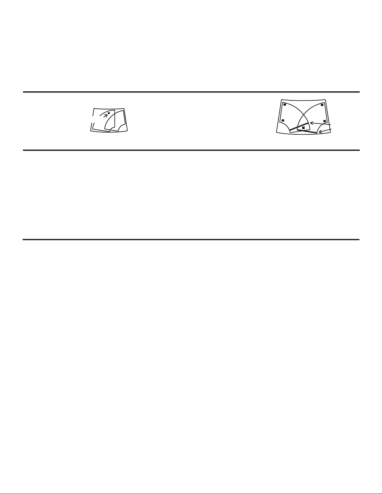
Some vehicles use a center-out wipe pattern.
The Rain Tracker needs to be in the area swept
by the wipers. It will not work if mounted behind
the rearview mirror on these vehicles. You can
locate the sensor between the wipers when they
are out of the park position, or up in a corner of
the windshield near the pillars-- but an inch and
half away enough from the edge of the pattern
so the wipers do not leave a film of water.
WIPER PATTERN COMPATIBILITY
TANDEM WIPE PATTERN
(TYPICAL INSTALLATION)
SENSOR
CENTER OUT-WIPE PATTERN
ALTERNATIVE SENSOR LOCATIONS
In most vehicles, the
wipers move from side
to side in tandem,
making it easy to mount
the Rain Tracker sensor
out of view, behind the
rearview mirror.
WIPERS OUT
OF PARK
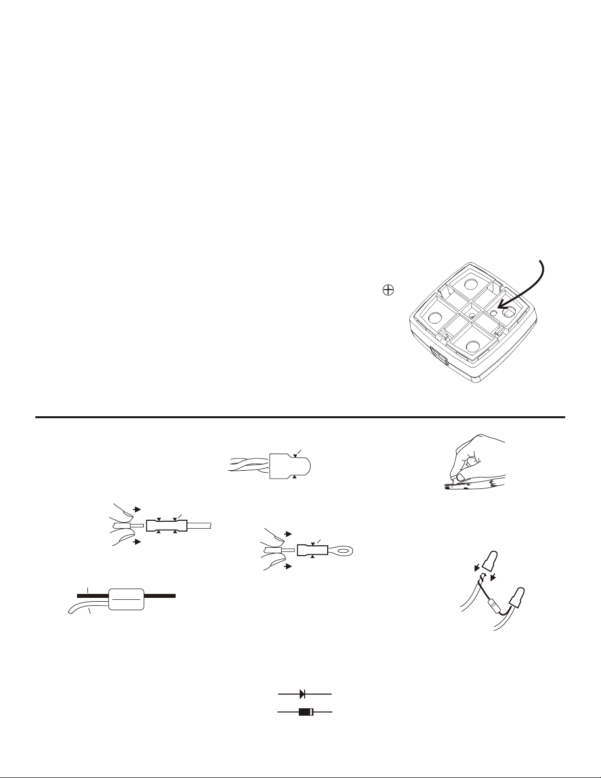
RAIN TRACKER SPECIFICATIONS:
Wiper relay contact ratings: 15A
Power diode rating: 6A continuous (used only intermittently in
application)
Input voltage: 10 - 16V, 12V nominal. 24V overvoltage protected.
Sensor operation: invisible infrared beams (880 nM)
Windshield thickness: 0.12” - 0.47” (3 - 12 MM)
Windshield transmittance requirement: 12% - 100% at 880 nM
Mechanical: Sensor: 1.75" x 1.75" x .75" / 1 oz.
Interface module: 4.45" x 2.45" x 1.15" / 4 oz.
HOW THE RAIN TRACKER RT-50A INTERFACE WORKS
ACTIVATION - The RT-50A is turned ON by connecting the mode reader
(J2 Pin 3, GRY) is to +12V
MANUAL MODES - The RT-50A Rain Tracker relies on the existing wiper
system to operate the wipers in manual slow, fast, intermittent, or wash.
AUTOMATIC INTERMITTENT MODE - When the RT-50A commands the
system to wipe intermittently, the slow relay pulses on. The fast relay
remains off.
AUTOMATIC STEADY SLOW MODE - The RT-50A turns on the slow
relay and leaves the fast relay off.
Rain Tracker Model RT-50A Installation Manual - Page 4 of 4
AUTOMATIC STEADY FAST - The RT-50A turns on both the slow and the
fast relays.
BLOCKING DIODE- The built-in rectifier (J2 pins 4 and 5) is provided so
that no Rain Tracker application ever shorts fast and slow windings
together, which would cause an over-current condition.
Other RainTracker Automobile Accessories manuals
Popular Automobile Accessories manuals by other brands

Metra Electronics
Metra Electronics Saddle Tramp BC-HDR-K4 quick start guide

Privacy Shades
Privacy Shades CIT-XSPI-5-A installation instructions

Volvo Penta
Volvo Penta 21573834 installation instructions

Metra Electronics
Metra Electronics 95-7324 installation instructions

Whispbar
Whispbar K677W Fitting instructions

3SIXT
3SIXT 3S-1186 operating instructions

Carefree of Colorado
Carefree of Colorado TRUCKIN' AWN Owner's Manual/Installation Instructions/Parts List

Prorack
Prorack K758 quick start guide

WIX
WIX WP9328 Installation instruction

MayPole
MayPole BC2085 manual

LEGENDEX
LEGENDEX ROGUE M.O.L.L.E MR-MP-COL-1 manual

Directed
Directed DBALL2-TL7 installation guide