RAK RAK7200 User manual

2
RA
K52
05
RAK7200 User Manual V1.1
RAK7200
Table of Contents
1 Overview..................................................................................................................................................... 4
1.1 Introduction......................................................................................................................................... 4
1.2 Main Features.................................................................................................................................... 4
2 LoRa Tracker Device RAK7200.............................................................................................................5
2.1 Overview............................................................................................................................................. 5
2.2 Block Diagram.................................................................................................................................... 5
2.3 Interfaces............................................................................................................................................ 6
2.4 LEDs.................................................................................................................................................... 6
2.5 Operating Frequencies..................................................................................................................... 7
2.6 Working Mode.................................................................................................................................... 7
2.7 Power Requirements.........................................................................................................................8
2.8 Environmental Requirements.......................................................................................................... 8
3 Built-in Antenna........................................................................................................................................ 9
3.1 GPS Antenna......................................................................................................................................9
3.2 LoRa Antenna.................................................................................................................................. 10
4 Upgrade Firmware................................................................................................................................. 11
5 AT commands......................................................................................................................................... 15
6 Contact Information...............................................................................................................................17
7 Revision History..................................................................................................................................... 18
8 Document Summary..............................................................................................................................18

3
RA
K52
05
RAK7200 User Manual V1.1
RAK7200
List of Tables
Table 1 | Operating Frequencies.................................................................................................................7
Table 2 | Power consumption...................................................................................................................... 8
Table 3 | Electrical Characteristics..............................................................................................................8
Table 4 | GPS Antenna Parameters........................................................................................................... 9
Table 5 | LoRa Antenna Gain.................................................................................................................... 10
Table 6 | AT Commands.............................................................................................................................16
List of Figures
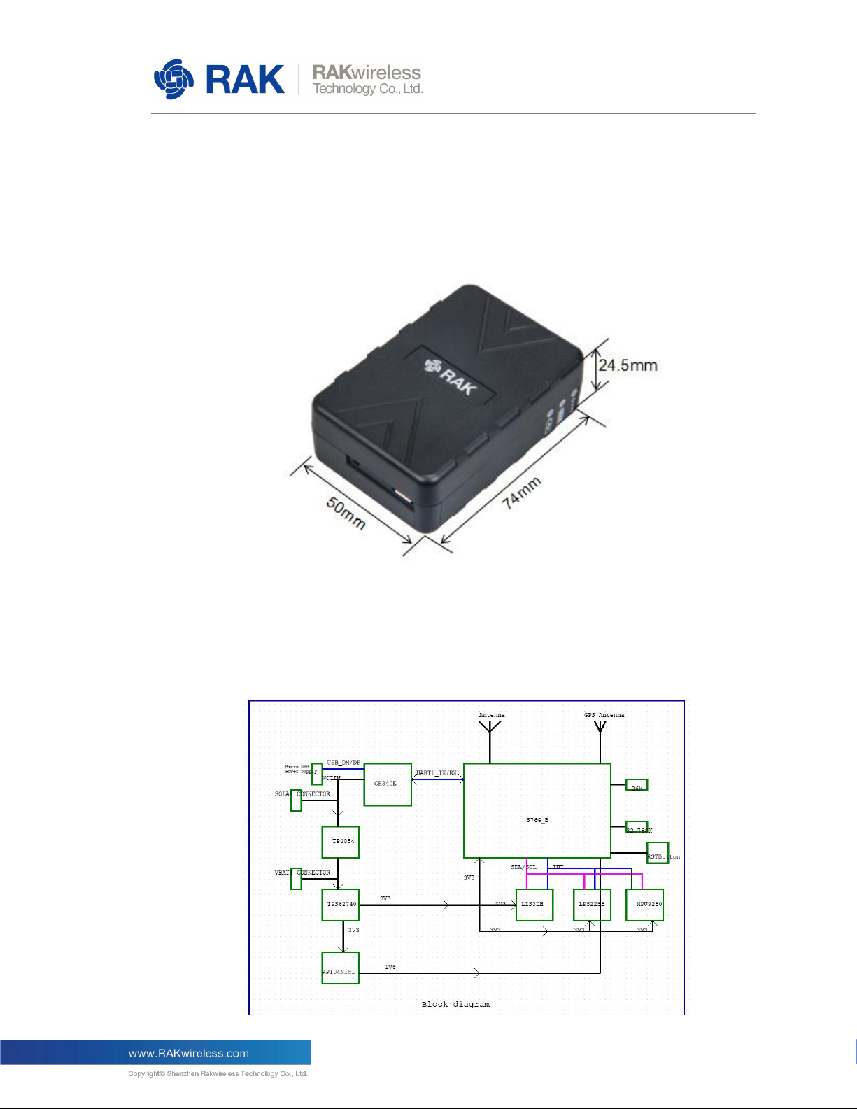
Figure 1 | RAK7200 OverView.....................................................................................................................5
Figure 2 | Block Diagram.............................................................................................................................. 5
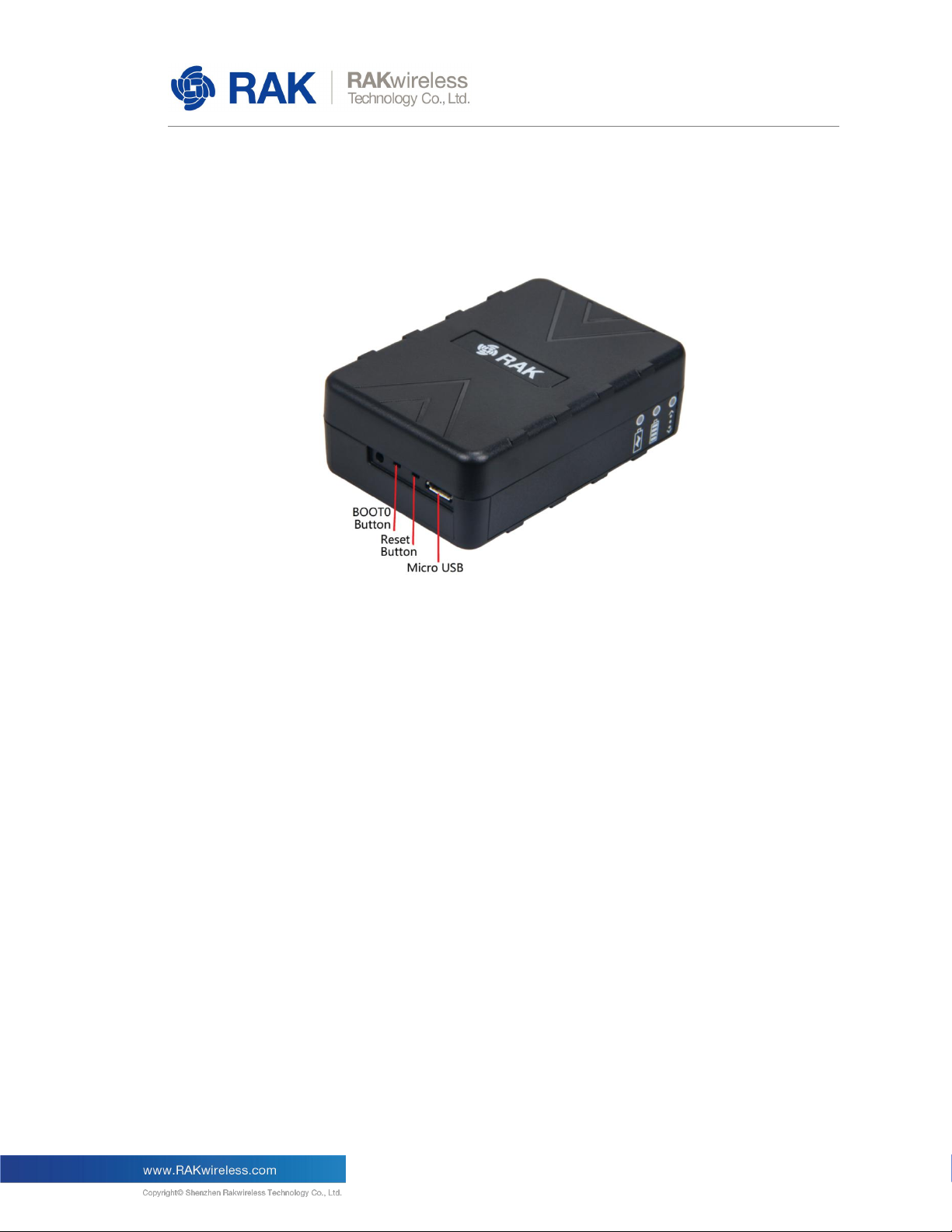
Figure 3 | Interfaces.......................................................................................................................................6
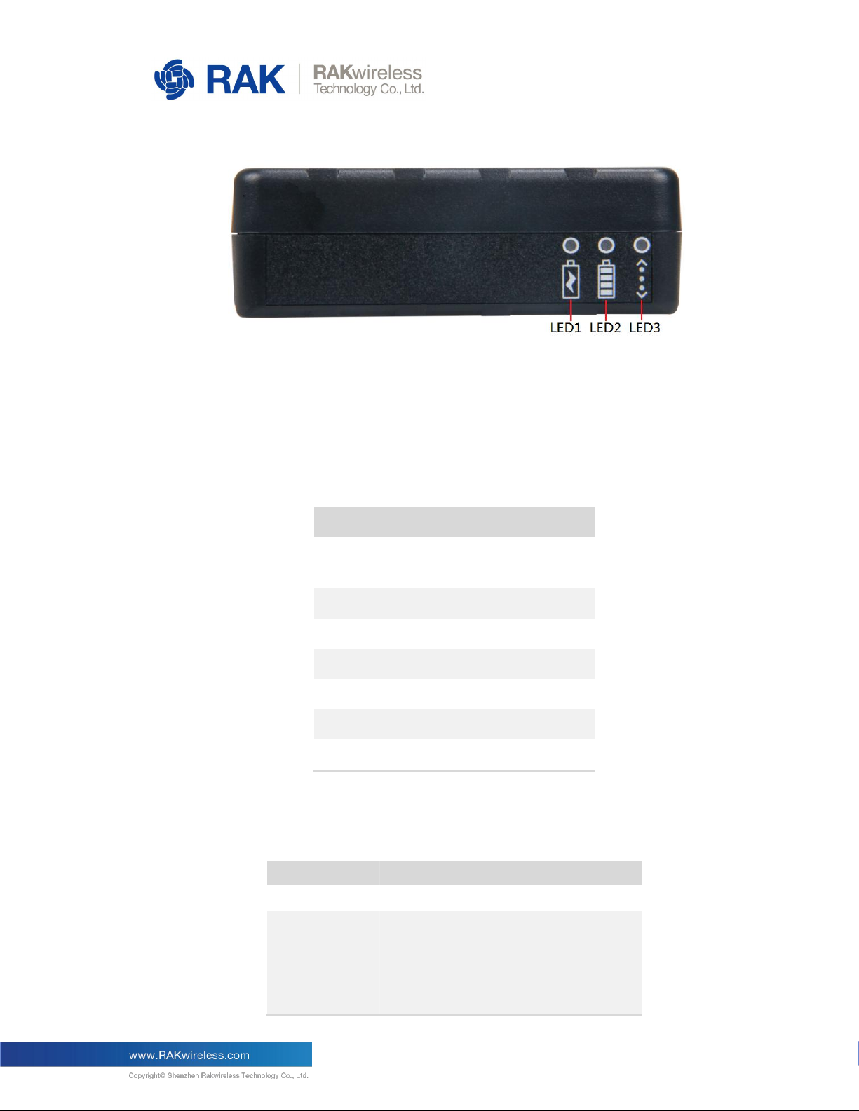
Figure 4 | LEDs.............................................................................................................................................. 7
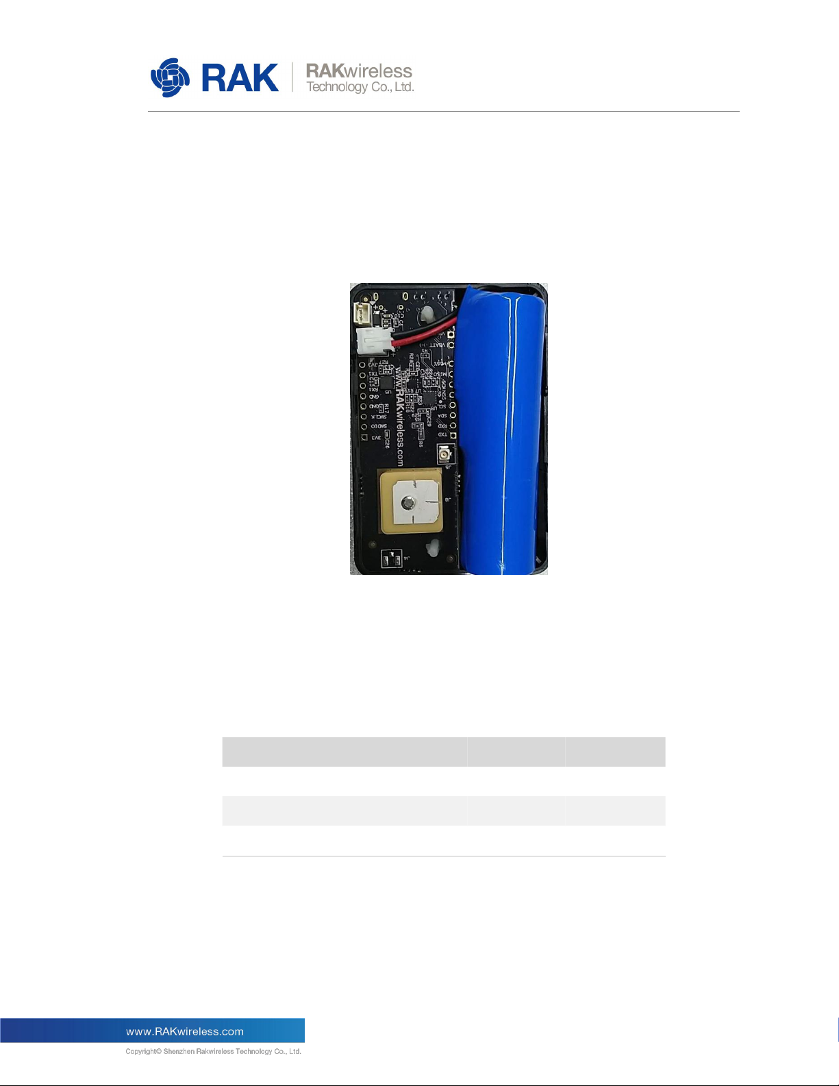
Figure 5 | Built-in Battery.............................................................................................................................. 8
Figure 6 | GPS Antenna................................................................................................................................9
Figure 7 | GPS Antenna S-parameter...................................................................................................... 10
Figure 8 | LoRa Antenna............................................................................................................................ 10
Figure 9 | LoRa Antenna performance.....................................................................................................10
Figure 10 | Upgrade Steps 1......................................................................................................................11
Figure 11 | Upgrade Steps 2......................................................................................................................12
Figure 12 | Upgrade Steps 3......................................................................................................................13
Figure 13 | Upgrade Steps 4......................................................................................................................13
Figure 14 | Upgrade Steps 5......................................................................................................................14
Figure 15 | Upgrade Steps 6......................................................................................................................14

4
RA
K52
05
RAK7200 User Manual V1.1
RAK7200
1Overview
1.1 Introduction
LoRa tracker device RAK7200 is the best available prototyping LoRa sensor device
with built-in 3.7V rechargeable Li-ion battery and GPS modem. The RAK7200 is built-in
S76G which integrats the ultra low power ARM Cortex-M3 STM32L073 microcontroller
and SX1276 LoRa long range modem and onboard CXD5603GF GPS modem. It is a
feature-packed tracker device for featured applications development.
It can as a quick prototyping tool for Internet-of-Things and LoRaWAN Network
integration. It is perfect for IoT applications such as asset tracking, smart vehicle
management and location-based services. And we provide the open source code which
make users quickly develop own applications.
1.2 Main Features
The main features are listed below:
Supports sleep mode, low power consumption.
Built-in digital output motion sensor LIS3DH, which has dynamic user selectable
full scales of ±2g/±4g/±8g/±18g and it is capable of measuring accelerations with
output data rates from 1Hz to 5kHz.
Built-in nano pressure sensor LPS22HB which functions as a digital output
barometer.
Built-in a 9-axis sensor which include the triple-axis gyroscope and the triple-axis
accelerometer and the triple-axis magnetormeter.
Supports latest LoRaWAN 1.0.2 protocol stack and supports Activation by
Personalization (ABP) or Over the Air (OTA) working mode.
Onboard Antennas for LoRa modem and GPS.
Supports Micro USB or built-in battery for power supply.
Supports global license-free frequency band: EU433, CN470, EU868, US915,
AS923, AU915, KR920 and IN865.

5
RA
K52
05
RAK7200 User Manual V1.1
RAK7200
2LoRa Tracker Device RAK7200
2.1 Overview
The picture below shows the external dimensions of the RAK7200 tracker device.
Figure 1 | RAK7200 OverView
2.2 Block Diagram
The block diagram below shows the internal architecture and external interfaces of the
RAK7200 tracker device.
Figure 2 | Block Diagram

6
RA
K52
05
RAK7200 User Manual V1.1
RAK7200
2.3 Interfaces
The RAK7200 device provides three external interfaces, as shown in the following figure.
Figure 3 | Interfaces
Micro USB
5V DC power supply and UART communication.
Reset Button
Reset Button is used to reset the RAK7200 device. Press the Reset Button for
more than 1 second, then the device will be reset.
BOOT0 Button
When upgrade the firmware, you need press and hold the BOOT0 Button, and then
press the reset button meanwhile to enter the boot mode.
2.4 LEDs
The device provides three LEDs for indicating the operating status, here are their
functions:
LED1 STATUS – indicates the Li-ion Battery is charging.
LED2 STATUS – indicates the Li-ion Battery is full charge.
LED3 STATUS – indicates the device is sending data.

7
RA
K52
05
RAK7200 User Manual V1.1
RAK7200
Figure 4 | LEDs
2.5 Operating Frequencies
The device supports all LoRaWAN frequency bands as below. Which is easy to
configure while building the firmware from the source code.
Region
Frequency ( MHz )
Europe
EU433, EU868
China
CN470
North America
US915
Asia
AS923
Australia
AU915
Korea
KR920
Indian
IN865
Table 1 | Operating Frequencies
2.6 Working Mode
Mode
Power consumption
Sleep mode
26uA
Normal mode
Tx @20dB 124mA
Tx @17dB 108mA
Tx @13dB 89mA
Tx @10dB 79mA
Tx @7dB 69mA
Rx 44mA

8
RA
K52
05
RAK7200 User Manual V1.1
RAK7200
Table 2 | Power consumption
2.7 Power Requirements
The RAK7200 tracker device is built-in a rechargeable 3.7V Li-ion battery which can be
charged via MicroUSB, the built-in battery is shown in the following figure.
Figure 5 | Built-in Battery
2.8 Environmental Requirements
The table below lists the operation and storage temperature requirements.
Parameter
Min.
Typical
Max.
Operation Temp. Range
-10 ºC
+25 ºC
+60 ºC
Extended Temp. Range
-10 ˚C
+80 ˚C
Storage Temp. Range
-10 ˚C
+80 ˚C
Table 3 | Electrical Characteristics

9
RA
K52
05
RAK7200 User Manual V1.1
RAK7200
3Built-in Antenna
The RAK7200 has a built-in passive GPS Antenna and an ipex LoRa Antenna. The
performance and parameters of the Antenna are as follows.
3.1 GPS Antenna
The GPS Antenna is shown in the following figure.
Figure 6 | GPS Antenna
The table below lists the parameters of the built-in GPS Antenna.
Items
Parameter
Outline Dimension
15×15×4mm
Frequency
1575.42MHz
Return Loss
≤ -10
Polarization
RHCP
Gain @Zenith
≥ -4dBi
Table 4 | GPS Antenna Parameters
S-parameter of the GPS Antenna as below.

10
RA
K52
05
RAK7200 User Manual V1.1
RAK7200
Figure 7 | GPS Antenna S-parameter
3.2 LoRa Antenna
The LoRa Antenna is shown in the following figure.
Figure 8 | LoRa Antenna
The table below lists the Efficiency/Gain of the built-in LoRa Antenna.
Freq
863M
928M
EFF
37.40%
40.40%
Gain(dBi)
0.23
1.25
Table 5 | LoRa Antenna Gain
LoRa Antenna return loss as shown below.
Figure 9 | LoRa Antenna performance

11
RA
K52
05
RAK7200 User Manual V1.1
RAK7200
4Upgrade Firmware
You can download the firmware of RAK7200 from here:
https://www.rakwireless.com/en/download/LoRa/RAK7200_Tracker_Device#Firmware
It is recommended to use Flash Loader Demonstrator to upgrade firmware.
You can download Flash Loader Demonstrator from :
https://www.rakwireless.com/en/download/LoRa/RAK811#Tools
Upgrade Steps :
1. Firstly connect the RAK7200 device to PC via microUSB and find the COM port. Then
open the Flash Loader Demonstrator and select the corresponding RAK7200 COM port and
set Baud Rate to “115200”, as shown in the following figure.
Figure 10 | Upgrade Steps 1
2. Enable the device to enter the BOOT mode(Press and hold the BOOT button of your
device, and then press the reset button), then click the ‘next’ to proceed.

12
RA
K52
05
RAK7200 User Manual V1.1
RAK7200
Figure 11 | Upgrade Steps 2
3. Select target as shown in the following figure, then click the ‘next’.

13
RA
K52
05
RAK7200 User Manual V1.1
RAK7200
Figure 12 | Upgrade Steps 3
4. Download the firmware to device as shown in the following figure, then click the ‘next’.
Figure 13 | Upgrade Steps 4
5. Then it will begin to download the firmware, as shown in the following figure.

14
RA
K52
05
RAK7200 User Manual V1.1
RAK7200
Figure 14 | Upgrade Steps 5
6. Now upgrade finished.
Figure 15 | Upgrade Steps 6

15
RA
K52
05
RAK7200 User Manual V1.1
RAK7200
5AT commands
You can use the AT commands listed in the table below to operate the RAK7200 device.
Item
AT Command
Set Device EUI
at+dev_eui=xxxxxxxxxxxxxxxx\r\n
e.g:at+dev_eui=60C5A8FFFF1Cxxxx\r\n
Set Application EUI
at+app_eui=xxxxxxxxxxxxxxxx\r\n
e.g:at+app_eui=70B3D57ED001xxxx\r\n
Set Application Key
at+app_key=xxxxxxxxxxxxxxxxxxxxxxxxxxx\r\n
e.g:at+app_key=F898136EB05B020DECE7D4A88851xxxx\r\n
Set Device Address
at+dev_addr=xxxxxxxxx\r\n
e.g:at+dev_addr=2604xxxx\r\n
Set Network Session Key
at+nwks_key=xxxxxxxxxxxxxxxxxxxxxxxxx\r\n
e.g:at+nwks_key=F5931FD0C62742D09BFCB942AF15xxxx\r\n
Set Application Session Key
at+apps_key=xxxxxxxxxxxxxxxxxxxxxxxxx\r\n
e.g:at+apps_key=79F2129C18A055BD5806CA84816Dxxxx\r\n
Set Activation Method
(otaa/abp)
at+join_mode=xxxx\r\n
e.g:at+join_mode=otaa\r\n
Set Region ( Frequencry:
US915/EU868/AU915/AS923/IN8
65/KR920 )
at+region=xxxx\r\n
e.g:at+region=US915\r\n
Set send data interval
( 60 ~ 86400 seconds )
at+app_interval=xxxx\r\n
e.g:at+app_interval=120\r\n
Set GPS Location wait time
( 30 ~ 600 seconds )
at+gps_stime=xxxx\r\n
e.g:at+gps_stime=30\r\n
Set Power Save mode
( 0: close , 1: open )
at+ps=x\r\n
e.g:at+ps=1\r\n
Get Device EUI
at+dev_eui\r\n
It will return the device eui

16
RA
K52
05
RAK7200 User Manual V1.1
RAK7200
Get Application EUI
at+app_eui\r\n
It will return the application eui
Get Application Key
at+app_key\r\n
It will return the app key
Get Device Address
at+dev_addr\r\n
It will return the device address
Get Network Session Key
at+nwks_key\r\n
It will return the network session key
Get Application Session Key
at+apps_key\r\n
It will return the application session key
Get Activation Method
at+join_mode\r\n
It will return the join method(otaa/abp)
Get data interval
at+app_interval\r\n
It will return the interval of send data
Get GPS Location wait time
at+gps_stime\r\n
It will return the GPS location wait time
Get Power Save mode
at+ps\r\n
It will return the power mode
Get Region
at+region\r\n
It will return the region
Table 6 | AT Commands

17
RA
K52
05
RAK7200 User Manual V1.1
RAK7200
6Contact Information
Shenzhen Business
ken.yu@rakwireless.com
Room 506, Bldg. 3, Minqi Technology Park, No.65 Taoyuan Road,
Xili Block, Nanshan District, Shenzhen
Shenzhen Technical
steven.tang@rakwireless.com
0755-86108311
Room 506, Bldg. 3, Minqi Technology Park, No.65 Taoyuan Road,
Xili Block, Nanshan District, Shenzhen

18
RA
K52
05
RAK7200 User Manual V1.1
RAK7200
7Revision History
Revision
Description
Date
1.0
Initial version
2019-02-26
1.1
Add AT commands chapter
2019-03-25
8Document Summary
Document Name: WisDevice LoRa Tracker RAK7200 User Manual
Product Name: RAK7200
Revision Number: V1.1
Prepared by
Checked by:
Approved by:
Hairui & Penn
About RAKwireless:
RAKwireless is the pioneer in providing innovative and diverse cellular and LoRa
connectivity solutions for IoT edge devices. It's easy and modular design can be used in
different IoT applications and accelerate time-to-market.
For more information, please visit RAKwireless website at www.rakwireless.com.
Table of contents
Other RAK GPS manuals