Ramix PMC233 Quick user guide

-~
ARTISAN
®
~I
TECHNOLOGY
GROUP
Your definitive source
for
quality
pre-owned
equipment.
Artisan Technology
Group
Full-service,
independent
repair
center
with
experienced
engineers
and
technicians
on staff.
We
buy
your
excess,
underutilized,
and
idle
equipment
along
with
credit
for
buybacks
and
trade-ins
.
Custom
engineering
so
your
equipment
works
exactly as
you
specify.
•
Critical
and
expedited
services
•
Leasing
/
Rentals/
Demos
• In
stock/
Ready-to-ship
•
!TAR-certified
secure
asset
solutions
Expert
team
ITrust
guarantee
I
100%
satisfaction
All
tr
ademarks,
br
a
nd
names, a
nd
br
a
nd
s a
pp
earing here
in
are
th
e property of
th
e
ir
r
es
pecti
ve
ow
ner
s.
Visit our website - Click HERE

Hardware Reference Manual
PMC233/4/5 &
PMC243/4/5 High
Capacity Disk Solutions
DDC No. Rx-URMH 090 Rev A
Issued 7 April 2002
0260307-000 / HARD DISK,IAS SBC,PMC MODULE,5XX
MFR PN: PMC233-R40

Hardware Reference Manual
PMC233/4/5 & PMC243/4/5 High Capacity Disk Solutions
Notice
The information contained in this manual has been carefully reviewed and is believed to be entirely accurate.
However, RAMiX shall not be liable for errors contained herein.
Users are encouraged to recommend improvements for future revisions.
RAMiX reserves all rights to make changes to improve reliability, function or design without notice.
Customer Support
Corporate Headquarters
RAMiX Inc.
1672 Donlon Street, Ventura, CA 93003, USA
Tel: 1+805-650-2111
•
Fax: 1+805-650-2110
http://www.ramix.com
RAMiX Europe Ltd.
3/2 Great Michael House, 14 Links Place
Edinburgh EH6 7EZ, United Kingdom
Tel: +44 131 561-3520
•
Fax: +44 131 561-3521
Copyright 2002 RAMiX Inc. All rights reserved. No part of this document may be reproduced, by any means,
without the prior written consent of the copyright holder. Reproduction without written consent constitutes
infringement under the Copyright Law of the United States.
DDC No. Rx-URMH 090 Rev A
Issued 7 April 2002
2 of 27

Hardware Reference Manual
PMC233/4/5 & PMC243/4/5 High Capacity Disk Solutions
This page intentionally left blank.
DDC No. Rx-URMH 090 Rev A
Issued 7 April 2002
3 of 27

Hardware Reference Manual
PMC233/4/5 & PMC243/4/5 High Capacity Disk Solutions
1 Introduction
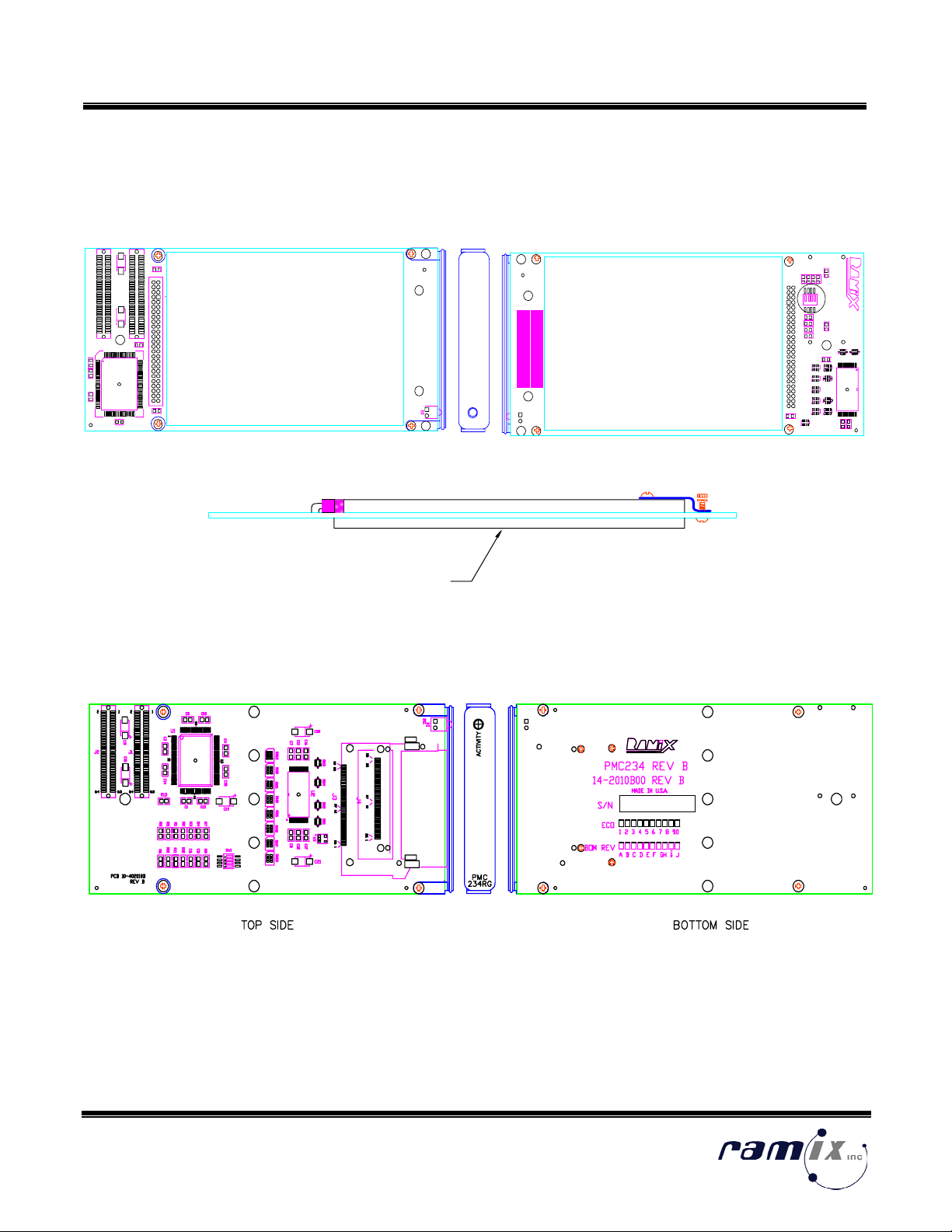
This manual describes the operation, configuration and installation instructions for the PMC23X and PMC24X
High Capacity Disk modules. The PMC23X/PMC24X family provides a single PMC slot storage solution utilizing
industry standard ATA rotating and solid state disks. Designed to be plugged onto a host processor (e.g., Single
Board Computer) card, these products provide an extremely compact, flexible and economical high performance
storage solution.
The PMC23X/PMC24X family of embedded disk modules offers a totally new high performance, low cost option
for file system and boot storage. Combining high performance controllers developed for high-end workstations,
with disk technology used in laptops, the PMC23X/PMC24X embedded disk module delivers very high data rates
in a compact form factor implemented with components designed for physically demanding environments. With
the PMC23X/PMC24X “single slot,” computing solutions do not need to compromise in either capacity or
performance. In addition, card edge PCI systems can be accommodated using RAMiX's PMC239 adapter for
rapid prototype and development.
The PMC23X/PMC24X is fully PMC compliant, meeting all mechanical, electrical and protocol specifications.
Disk capacities from 10GB to 60GB (rotating media) and from 32MB to 2GB (Flash) are supported.
The PCI controller on the PMC23X/PMC24X makes full and efficient use of the PCI bandwidth. FIFO buffers
allow effective use of PCI burst modes, critical to achieving low PCI overheads. The PMC23X/PMC24X can
execute data transfers at full PCI bus speeds. The PMC23X/PMC24X will mount on any PMC location (either
directly on a processor card or on a PMC carrier board).
On the disk side, the controller can support ATA 66 for the PMC 233/234/235 and ATA 100 on the
PMC243/244/245.
1.1 Features
The PMC233 and PMC234 use the CMD Technology CMD646 controller, the PMC235 uses the CMD648
controller. The PMC243, PMC244 and PMC245 use the Promise Technology PDC20269 controller (fully PCI 2.1
compliant). The most significant difference between the two sets of products is the performance, both on the PCI
(the PMC233, PMC234 and PMC235 supports 32bit/33Mhz, the PMC243, PMC244 and PMC245 supports 32 bit
wide PCI and speeds up to 66Mhz) and on the ATA (to disk) bus.
Within each group, the products are distinguished by mechanical layout and the style of disk they support.
All of these modules comply with the CMC specification for PCI Mezzanine Cards (commonly known as PMC).
As such, they will directly connect to any Single Board Computer (SBC) or Expansion Card that supports PMC
modules. All initialization, and functional configuration of the module is done automatically by software.
All of the products offer:
• Boot OS (e.g. Windows, NT, RTOS, etc.)
• Runs under the local Operating System File System
• Utilize industry standard storage solutions (e.g., 2.5” and Compact FLASH drives), allowing capacity and
performance improvements as they become available.
• Drivers for most popular RTOS, UNIX and Microsoft Window environments
DDC No. Rx-URMH 090 Rev A
Issued 7 April 2002
4 of 27

Hardware Reference Manual
PMC233/4/5 & PMC243/4/5 High Capacity Disk Solutions
1.2 Model Comparison
Model No. Drive Types
Supported
PCI
Specification
s
Drive Integration Number Of
Drives
Supported
PMC233 2.5” Rotating
Media
2.5” Solid State
Media
32bit/33Mhz Integrated into PMC
assembly
1
PMC243 2.5” Rotating
Media
2.5” Solid State
Media
32bit/33Mhz
32bit/66Mhz
Integrated into PMC
assembly
1
PMC234FP CompactFlash
MicroDrive
32bit/33Mhz Inserted via front panel 1
PMC244FP CompactFlash
MicroDrive
32bit/33Mhz
32bit/66Mhz
Inserted via front panel
Up to two additional via J4
3
PMC234RG CompactFlash
MicroDrive
32bit/33Mhz Recessed behind front
panel
1
PMC244RG CompactFlash
MicroDrive
32bit/33Mhz
32bit/66Mhz
Recessed behind front
panel
Up to two additional via J4
2
PMC235 Any ATA/IDE
compatible drive.
32bit/33Mhz External to module via
ribbon cable or rear
transition
4
PMC245 Any ATA/IDE
compatible drive.
32bit/33Mhz
32bit/66Mhz
External to module via
ribbon cable or rear
transition
4
1.2.1 PMC233/PMC243
These two products offer high capacity, high performance disk solutions. They integrate a 2.5” disk (either
rotating or Solid State) directly into the product assembly. As such they provide a small form factor rugged
storage solution for embedded systems.
DDC No. Rx-URMH 090 Rev A
Issued 7 April 2002
5 of 27

Hardware Reference Manual
PMC233/4/5 & PMC243/4/5 High Capacity Disk Solutions
Features include:
• Boot and Runtime file system solution in a single slot
• Rotating Media from 10GB to 60GB
• Flash disk from 32MB to 2GB
• Flash option available in Industrial Temperatures
• Fast read/write performance (rotating media)
• Compact and extremely rugged
1.2.2 PMC234/PMC244
Industry standard CompactFlash/MicroDrive storage devices are accommodated either via front panel (excellent
for situations where the storage needs to be easily transportable), or recessed for higher mechanical robustness.
(NB: the PMC234/PMC244 do not have hot swap support, power must be off before removing/inserting the
drive).
• Compact Flash/MicroDrive Host Bus Adapter
• Single PMC form factor
• PCI 32/66Mhz (PMC244 only
• PCI Rev. 2.1 compliant (PMC 234 only
• Available with front panel ejector or recessed
• Compact Flash cards up to 512MB
• Magnetic disks up to 1GB
1.2.3 PMC235/PMC245
The PMC235/PMC245 has an IDE header in the front to attach low cost IDE disks. They also route the IDE
signals to the “J4” connector for the rear I/O. The PMC235/PMC245 has options for both the popular 44 pin as
well as the 40 pin headers for its front panel connector. These versions were developed to provide maximum
flexibility: supporting the widest range of disk drive solutions and allowing integration to specialized system
configurations.
• Two independent IDE/ATA Channels
• Single PMC form factor (PMC235 only)
• PCI 32/66Mhz (PMC245 only)
• Available with front panel IDE
• Supports Ultra and Multiword DMA (PMC235 only)
• Supports Utra ATA 100 (PMC245 only)
DDC No. Rx-URMH 090 Rev A
Issued 7 April 2002
6 of 27
• Bus Master DMA at 133 MBytes/sec

Hardware Reference Manual
PMC233/4/5 & PMC243/4/5 High Capacity Disk Solutions
1.3 Environmental Data for Micro Drives for PMC234/PMC244
• Ambient temperature 5 to 55°C −40 to 65°C
• Relative humidity (non-condensing) 8% to 90% 5% to 95%
• Maximum wet bulb (non-condensing) 29.4 40
• Shock (half sine wave) 150 G (2 ms) 1000 G (1 ms)
• Vibration (random [RMS]) 0.67 G (5 to 500 Hz) 3.01 G (5 to 500 Hz)
• Vibration (swept sine) 1 G 0-peak (5 to 500 Hz) NA
DDC No. Rx-URMH 090 Rev A
Issued 7 April 2002
7 of 27

Hardware Reference Manual
PMC233/4/5 & PMC243/4/5 High Capacity Disk Solutions
2 Hardware Installation
This chapter provides unpacking, hardware preparation and installation procedures for the PMC233/PMC243
modules.
2.1 Unpacking Instructions
RAMiX’s boards are protected by an anti-static envelope and/or wrapping. Observe anti-static precautions and
work at an approved anti-static workstation when unpacking the board.
Note: The units are shipped in an individual, reusable shipping box. When the shipping
container is received, inspect it for any evidence of physical damage. If the container is
damaged, request that the carrier’s agent be present during unpacking and inspection of
the unit.
Unpack the module from shipping carton. Check and verify that all items are present by referring to the packing
list.
2.2 Included Items
Each PMC23X/PMC24X is shipped with a corresponding PMC assembly.
2.3 Handling
Electronic assemblies use devices that are sensitive to static discharge; this applies to both the
PMC23X/PMC24X and the host board onto which it will be mounted. Observe anti-static procedures when
handling these boards. The PMC23X/PMC24X should be in an anti-static plastic bag or conductive foam for
storage or shipment.
DDC No. Rx-URMH 090 Rev A
Issued 7 April 2002
8 of 27

Hardware Reference Manual
PMC233/4/5 & PMC243/4/5 High Capacity Disk Solutions
3 Mechanical Information and Front Panel Layout
3.1 PMC233 Top/Bottom Drawings (do not change switch setting)
R
MADE IN U.S.A.
PN 700790 REV.B
R2
R3
RN3
RN2
RN8
RN10
RN7
RN11
RN12
RN1
U2
RN6
RN9
RN5
R6
PMC233
R12
C1
RN4
R1
R5
4
3
2
1
R7
C4
SW1
S/ N
D/ C
C6
R10
R11
R9
R8
J3
C10
R13
C8
4
C2
C5
U1
+
C7
J2
C9
J1
DS1
C3
+
TOP SIDE BOTTOM SIDE
PMC
233
ACTIVITY
IBM TRAVELSTAR HARD DRIVE
VARIOUS SIZES AND CONFIGURATIONS
3.2 PMC234 Top/Bottom Drawings
DDC No. Rx-URMH 090 Rev A
Issued 7 April 2002
9 of 27

Hardware Reference Manual
PMC233/4/5 & PMC243/4/5 High Capacity Disk Solutions
3.3 PMC235 Top/Bottom Drawings
C3
J2
C4
J4
TOP SIDE
PCB 10-402220A 1 2 3 4
C5
C2
J1
C1
R9
R10
R13
R8
R12
R11
P3 P4
P1
R3
R2
P2
26 1
64 63
2
64
1
63 64 63
2121
50 25 37 12 26 1 50 25 37 12
43
44
1
2
BOTTOM SIDE
PMC235 REV A
S/N
BOM REV
1 2 3 4
A B C D E F
14-2220A00
1 2 3 4 5 6
ECO
MADE IN U.S.A.
RN7
RN11RN9
RN10
RN12
RN8
RN6
RN5
RN4
RN2
RN3
RN1
R1
C11
U2
RN13
RN16
C18
U1
RN14
L1
C20
C19
R5
C12
C15
C10
C7
C17
C16
R4
R6
U3
C13
C8
C6
C9
R7
RN15
C14
SW1
R15
R14
U4
DS1
160
20
120
140
100
40
60
4
3
2
1
80
40
39
2
1
PMC235
ACT
10
VIEW A
PMC235 & PMC235
/
(P1 INSTALLE
D
PMC235
ACT
10
VIEW B
PMC235/44 & PMC235/44/
(P2 INSTALLED)
DDC No. Rx-URMH 090 Rev A
Issued 7 April 2002
10 of 27

Hardware Reference Manual
PMC233/4/5 & PMC243/4/5 High Capacity Disk Solutions
3.4 PMC243 Top/Bottom Drawings
C13
J2
C14
64
C22
1
C21
TOP SIDE BOTTOM SIDE
PMC243 REV C
14-2800C00
MADE IN U.S.A.
1 2 3 4 5 6
ECO
S/N
C26
C8
RN4
RN5
C7
C25
C17
R5
RN6
C27
C28
RN1
RN2
R9
R10
C23
C6
C30
RN3
R6
RN9
C1
C19
RN8
RN7
C29
R4
C15
C18
PCB 10-602800C
C11
C20
C12
C16
R7
R3
C4
U1
C5
C2
C24
C37
J3
C3
R2
R1
C10
J1
C9
R8
DS1
45
39
38 65
64
44
128
102
63 64 63
2112
46
43
1
PMC
243
ACTIVITY
2.5" HARD DRIVE OR SSD
VARIOUS SIZES AND CONFIGURATIONS
3.5 PMC244 Top/Bottom Drawings
R1
2
C1
C15
C34
C33
PCB 10-602810A
RN10
J4
R7
C17
C18
U3
RN13
RN16 RN15
RN11
R9
C35
RN12RN14
C10
C23
J2 J1
C25
C9
C26
U1
R5
C32
RN6RN9RN5 RN7
C20
C27
C16
U2
RN3
C8
RN4
RN1
C7
RN8
R4
C29
C14
RN2
C22
C24
C4
C3
C5
R3
C2
C28
C30
R2
C21
C13
C1C6
R8
R6
C11
C19
P1
P2
C31 R11
R10
DS1
64 63
2
64
1
63 64 63
38
2112
1
39 64
65
128
102
103
25 50
12 371 26 25 50
12 371 26
PMC244 REV A
14-2810A00
MADE IN U.S.A.
1 2 3 4 5 6
ECO
S/N
PMC
244RG
ACT
01
PMC
244FP
ACT
01
-OR-
DDC No. Rx-URMH 090 Rev A
Issued 7 April 2002
11 of 27

Hardware Reference Manual
PMC233/4/5 & PMC243/4/5 High Capacity Disk Solutions
3.6 PMC245 Top/Bottom Drawings
C2
C5
TOP SIDE BOTTOM SIDE
1 2 3 4 5 6
PMC245 REV A
40
39
14-2830A00
S/N
C16
C38
C41
C21
MADE IN U.S.A.
ECO
1
2
RN3 C36
U1
C8
RN12
C18
R7
C22
C13
C37
R8
R9
C30
C12
RN6
U2
C9
RN11
C20
RN13
C40
C15
C14
RN16
RN5 RN8
RN7
C27
RN4
RN17
C17
RN18
RN10
C11
R4
C19
R1
64
C7
RN14
63
65
64
J4
2
64
38
39
1
U3
63
C4
64
C6
63
2
J2
211
C3
J1
C1
RN9
C23
PCB 10-602830A
C35
C34
102
C26
R5
R10
C33
R14
RN15
R11
R16
C24
C28
RN1
50
1
R6
C25
25 C29 P3 37 12 26 1 2550 P4 37 12 26
C10
C32
43
44
1C39
P1
DS1
C31
R3
R2
1
2P2
VIEW A
PMC245 & PMC245/CF
(P1 INSTALLED)
VIEW B
PMC245/44 & PMC245/44/
(P2 INSTALLED)
PMC245
ACT
10
PMC245
ACT
10
DDC No. Rx-URMH 090 Rev A
Issued 7 April 2002
12 of 27

Hardware Reference Manual
PMC233/4/5 & PMC243/4/5 High Capacity Disk Solutions
3.7 Assembly Diagram
The PMC23X/PMC24X module is now ready for installation. Turn all system power off. Remove the host board
from the chassis (if currently installed). Locate the PMC connectors on the host board. Carefully plug the
PMC23X or PMC24X into the mating connectors on the host's printed circuit board. Be sure module is seated
properly into CMC connectors on the host. Use screws to fasten module into host PCB.
1. Remove the four screws from the bottom of the stand-offs.
2. Line up the J1 and J2 connectors on the host PCB to the PMC23X/PMC24X J1 and J2 connectors.
3. Push the PMC23X/PMC24X down, making sure all connectors are positioned properly.
4. Use the four screws to connect the PMC23X/PMC24X stand-offs to the host PCB.
DDC No. Rx-URMH 090 Rev A
Issued 7 April 2002
13 of 27

Hardware Reference Manual
PMC233/4/5 & PMC243/4/5 High Capacity Disk Solutions
3.8 Front Panel Indicators
The ACTIVITY LED illuminates when activity (Rx or Tx) is present on the port.
PMC233
Activity LED illuminates on
access.
PMC234FP
Activity LED illuminates on
access.
PMC
234
ACT
DDC No. Rx-URMH 090 Rev A
Issued 7 April 2002
14 of 27

Hardware Reference Manual
PMC233/4/5 & PMC243/4/5 High Capacity Disk Solutions
PMC235
Activity LED illuminates on
access. Individual LED for
each drive.
PMC234RG
Activity LED illuminates on
access.
PMC
234RG
ACTIVITY
PMC235
ACT
10
DDC No. Rx-URMH 090 Rev A
Issued 7 April 2002
15 of 27

Hardware Reference Manual
PMC233/4/5 & PMC243/4/5 High Capacity Disk Solutions
DDC No. Rx-URMH 090 Rev A
Issued 7 April 2002
16 of 27
PMC243
Activity LED illuminates on
access.
PMC244FP
LED0 for the drive mounted on
the PCB.
LED1 for the drive attached via
the “J4” connector.

Hardware Reference Manual
PMC233/4/5 & PMC243/4/5 High Capacity Disk Solutions
DDC No. Rx-URMH 090 Rev A
Issued 7 April 2002
17 of 27
PMC245
Activity LED illuminates on
access. Individual LED for
each drive.
PMC244RG
LED0 for the drive mounted on
the PCB.
LED1 for the drive attached via
the “J4” connector.
PMC
244RG
ACT
01
PMC245
ACT
1 0

Hardware Reference Manual
PMC233/4/5 & PMC243/4/5 High Capacity Disk Solutions
4 Architecture
The PMC23X/24X utilizes a single chip solution that interfaces the PCI to the ATA bus. The PMC23X is ATA66,
compatible while the PMC24X extends the compatibility to ATA100. The PMC23X has a 32/33Mhz PCI bus
interface. The PMC24X has a 32/66Mhz PCI bus interface. Further, the PCI bus signaling of the PMC23X is +5V
only, while the PMC24X is +3.3V as well as +5V.
SecondaryPrimary IDE Primary IDE
ATA/
IDE
ATA/
IDE
PCI/IDE Controller
Host PCI
Connection
PCI/IDE Controller
Host PCI
Connection
ATA/
IDE
PMC235, PMC243 & PMC245PMC233 & PMC234
Each IDE bus (i.e. Primary and Secondary) can have up to two drive units attached. Connecting more than one
drive is constrained by mechanical configuration on each product (see table in the Model Comparison section.)
DDC No. Rx-URMH 090 Rev A
Issued 7 April 2002
18 of 27

Hardware Reference Manual
PMC233/4/5 & PMC243/4/5 High Capacity Disk Solutions
5 Switch Settings
In general switch settings should not be changed from the factory default.
Note:Switches can be labeled On/Off or Close/Open. (On corresponds to Close, Off to Open)
PMC233 & PMC234
SW1 Factory
Default
Description
1 Off If On Base Address Registers are disabled. IDE task
registers will default to 0x1Fx (Primary) and 0x17x
(Secondary)
2 On Disable Native Mode
3 Off Must be off for correct operation
4 On Don’t Care
PMC235
SW1 Factory
Default
Description
1 Off Must be Off for correct operation
2 Off Off to disable native mode operation
3 On Off to force operation as legacy mode device
4 On I/O control
DDC No. Rx-URMH 090 Rev A
Issued 7 April 2002
19 of 27
This manual suits for next models
5
Table of contents
Other Ramix Recording Equipment manuals