Ramix PMC665 User manual

Artisan Technology Group is your source for quality
new and certied-used/pre-owned equipment
• FAST SHIPPING AND
DELIVERY
• TENS OF THOUSANDS OF
IN-STOCK ITEMS
• EQUIPMENT DEMOS
• HUNDREDS OF
MANUFACTURERS
SUPPORTED
• LEASING/MONTHLY
RENTALS
• ITAR CERTIFIED
SECURE ASSET SOLUTIONS
SERVICE CENTER REPAIRS
Experienced engineers and technicians on staff
at our full-service, in-house repair center
WE BUY USED EQUIPMENT
Sell your excess, underutilized, and idle used equipment
We also offer credit for buy-backs and trade-ins
www.artisantg.com/WeBuyEquipment
REMOTE INSPECTION
Remotely inspect equipment before purchasing with
our interactive website at www.instraview.com
LOOKING FOR MORE INFORMATION?
Visit us on the web at www.artisantg.com for more
information on price quotations, drivers, technical
specications, manuals, and documentation
Contact us: (888) 88-SOURCE | sales@artisantg.com | www.artisantg.com
SM
View
Instra

PMC665 Intelligent Dual ETHERNET Interface Card
Hardware Reference
and
Installation Manual
1672 Donlon Street, Ventura, CA 93003 U.S.A., Tel: (805) 650 2111, FAX: (805) 650 2110
Customer Support E-mail: support@ramix.com
Document ID Rx-URME-007
Revision: Rev -
Issue Date: April 25, 2001
Artisan Technology Group - Quality Instrumentation ... Guaranteed | (888) 88-SOURCE | www.artisantg.com

Rx-URME-007 Rev - -2 - Preliminary - PMC665 Hardware Reference and Installation Manual Page 2
Preface
Purpose
This manual describes the design and operational features of the PMC665 Intelligent Dual
Ethernet card, as well as installation procedures for attaching the card on a host Single Board
Computer (SBC).
Audience
This manual is intended to guide installation, configuration and maintenance of the Ethernet
Switch product.
The information in this manual has been carefully reviewed and is believed to be entirely accurate.
However, RAMiX shall not be liable nor responsible for errors contained herein.
RAMiX reserves all rights to make any changes to improve the reliability, function or design,
without any notice.
Conventions
This manual uses the following conventions:
Convention Meaning
Return Press the key that executes commands or terminates a sequence. This key is labeled
Return or Enter depending on your keyboard.
<CTRL> X While you hold down the Ctrl key, press any other key. RAMiX monitor commands are
case sensitive. You must enter commands in the correct case, as printed in the text.
Courier type Indicates examples of system output or user input.
Italics In commands and examples, italics indicate a value (e.g., the name of a file) that you
should supply.
[ ] Square brackets in command descriptions enclose the optional command qualifiers. Do
not type the brackets when entering information enclosed in the brackets.
|A vertical bar in command descriptions indicates that you have a choice between two or
more entries. Select one entry unless the entries are optional.
{ } Braces indicate that you are required to specify one (and only one) of the enclosed
options. Do not type the braces when you enter the command.
( ) Parentheses enclose a set of options that must be specified together.
0xNNNN Hexadecimal values are indicated with the 0x prefix.
Artisan Technology Group - Quality Instrumentation ... Guaranteed | (888) 88-SOURCE | www.artisantg.com

Rx-URME-007 Rev - -2 - Preliminary - PMC665 Hardware Reference and Installation Manual Page 3
1 General Information
1.1 Introduction
This manual describes operation, configuration and installation instructions for the RAMiX,
PMC665 PMC Module. The PMC665 is an Intelligent Dual Ethernet interface card, offering two,
fully independent 100 Mbit Ethernet channels using multi mode Fiber media (100BaseFx).
Designed to be plugged onto a host processor (e.g., Single Board Computer) board, the PMC665
provides an extremely compact, economical high performance Ethernet solution. Incorporating an
on-module I/O co-processor, the PMC665 allows off-loading of the host processor of high over
tasks.
1.2 Features
The PMC665 complies with the CMC specification for PCI Mezzanine Cards (commonly known as
PMC). As such, it will directly connect to any Single Board Computer (SBC), or Expansion Card
that supports PMC modules. All initialization and functional configuration of the PMC665 is done
automatically by software. Features implemented on the PMC665 include:
• Two, independent 100Mbit Ethernet controllers drive separate multi mode Fiber
connections
• Full duplex operation is supported
• Automatic power up configuration per PCI specification
• On module I/O co-processor with local instruction and data store allows the PMC665
to present application specific functional support such as:
• High performance Point-to-Point data mover, separate from standard network
protocol stack
• Fault tolerant data monitoring
Artisan Technology Group - Quality Instrumentation ... Guaranteed | (888) 88-SOURCE | www.artisantg.com

Rx-URME-007 Rev - -2 - Preliminary - PMC665 Hardware Reference and Installation Manual Page 4
2 Hardware Installation
2.1 Introduction
This chapter provides unpacking, hardware preparation, and installation procedures for the
PMC665 module.
2.2 Unpacking Instructions
RAMiX boards are protected by an anti-static envelope and/or wrapping. Observe anti-static
precautions and work at an approved anti-static workstation when unpacking the board
Note:The PMC665 is shipped in an individual, reusable shipping box. When you receive the
shipping container, inspect it for any evidence of physical damage. If the container is
damaged, request that the carrier’s agent be present during unpacking and inspection of the
unit.
Unpack the PMC665 module from shipping carton. Check to verify that all items are present by
referring to the packing list.
2.2.1 Included Items
Each PMC665 is shipped with the following items:
• PMC665 PMC Assembly
2.3 Handling
Electronic assemblies use devices that are sensitive to static discharge; this applies to both the
PMC665 and the host board on to which it will be mounted. Observe anti-static procedures when
handling these boards. The PMC665 should be in an anti-static plastic bag or conductive foam for
storage or shipment.
2.4 PMC665 Installation
The PMC665 Module is now ready for installation. Turn all system power off. Remove the host
board from the chassis (if currently installed). Locate the PMC connectors on the host board.
Carefully plug the PMC665 into the mating connectors on the host’s printed circuit board. Be sure
Artisan Technology Group - Quality Instrumentation ... Guaranteed | (888) 88-SOURCE | www.artisantg.com

Rx-URME-007 Rev - -2 - Preliminary - PMC665 Hardware Reference and Installation Manual Page 5
module is seated properly into CMC connectors on the host. Use screws to fasten module into
host PCB.
1. Remove the four screws from bottom of the stand-offs of the PMC665.
2. Line-up the J1 and J2 on the host PCB to PMC665, J1 & J2.
3. Push the PMC665 down (make sure the connectors J1 and J2 are positioned properly).
4. Use the four screws to connect the PMC665 stand offs to the host PCB.
2.5 Connection to the Local Network Media
The PMC665 has two fiber transceiver connections on the front panel, one for each Ethernet
channel. Connection is made using industry standard fiber cables.
2.6 POINT to POINT Operation
Two PMC665 modules may be connected “back to back” for direct connection using standard
Fiber cabling.
Artisan Technology Group - Quality Instrumentation ... Guaranteed | (888) 88-SOURCE | www.artisantg.com

Rx-URME-007 Rev - -2 - Preliminary - PMC665 Hardware Reference and Installation Manual Page 6
3 PMC665 Architecture
The PMC665 is a complete I/O subsystem, illustrated in the block diagram below:
3.0.1 PMC665 Subsystems
At the functional center of the PMC665 is the integrated bridge/Co-processor unit. Combining the
bridge and co-processor creates a high bandwidth, low latency integration between the
computational capabilities of the co-processor and the data flow of the bridge.
3.0.2 Transaction Isolation
There are three, independent busses contained on the PMC665: Host PCI bus, Secondary PCI
bus and Local co-processor bus. Data can flow between any pair; transactions have no affect on
traffic on the third bus. Thus, control and data flow between the Co-processor and local memory
system will consume no bandwidth on the Host PCI. It is this isolation that allows the PMC665 to
perform arbitrary manipulation, filter, etc., of data from the Ethernet, without compromising the
host system performance. The Co-processor/Bridge controller contains DMA engines, with FIFO
buffers to each of the busses. This is a critical factor, as the actual (opposed to theoretical)
bandwidth of a PCI bus decreases dramatically without burst (and relatively long burst) transfers.
3.0.3 Co-processor
The co-processor is an Intel i960 RISC CPU. The i960 architecture excels at data movement and
control, exactly the requirements of an I/O co-processor. Highly integrated, the i960 conforms
quite closely to the generic RISC architecture definition: single cycle instruction execution, multiple
Host PCI
100Mbit
MAC
Local PCI Bus
PCI/PCI DRAM
Buffer &
Firmware
Boot
FLASH
Bridge
Fiber
Transceiver
100Mbit
MAC
Fiber
Transceiver
Artisan Technology Group - Quality Instrumentation ... Guaranteed | (888) 88-SOURCE | www.artisantg.com

Rx-URME-007 Rev - -2 - Preliminary - PMC665 Hardware Reference and Installation Manual Page 7
registers, load/store memory access, etc. In addition, the i960 features a “register stack”
mechanism that maintains initial interrupt response on chip, which improves performance and
determinism.
The co-processor can initiate all transaction types on each of the three buses.
Included in the bridge/co-processor are the DMA engines (described earlier), several counter/
timers to support time based event activity of the firmware and an interrupt multiplexer/handler for
responding to the Ethernet controllers. Both register and message based interfaces to the host
processor are available, allowing support of a variety of control paradigms. This greatly simplifies
integrating the PMC665 into some existing software environments, while preserving the ability to
develop higher performance complex message based controls.
Integrating the processor and bridge has the useful side effect of exposing most of the control
logic to the host processor (mapped into the PCI Configuration space and optionally the memory
space of the host). This creates the option for a continuum of control distribution, between the
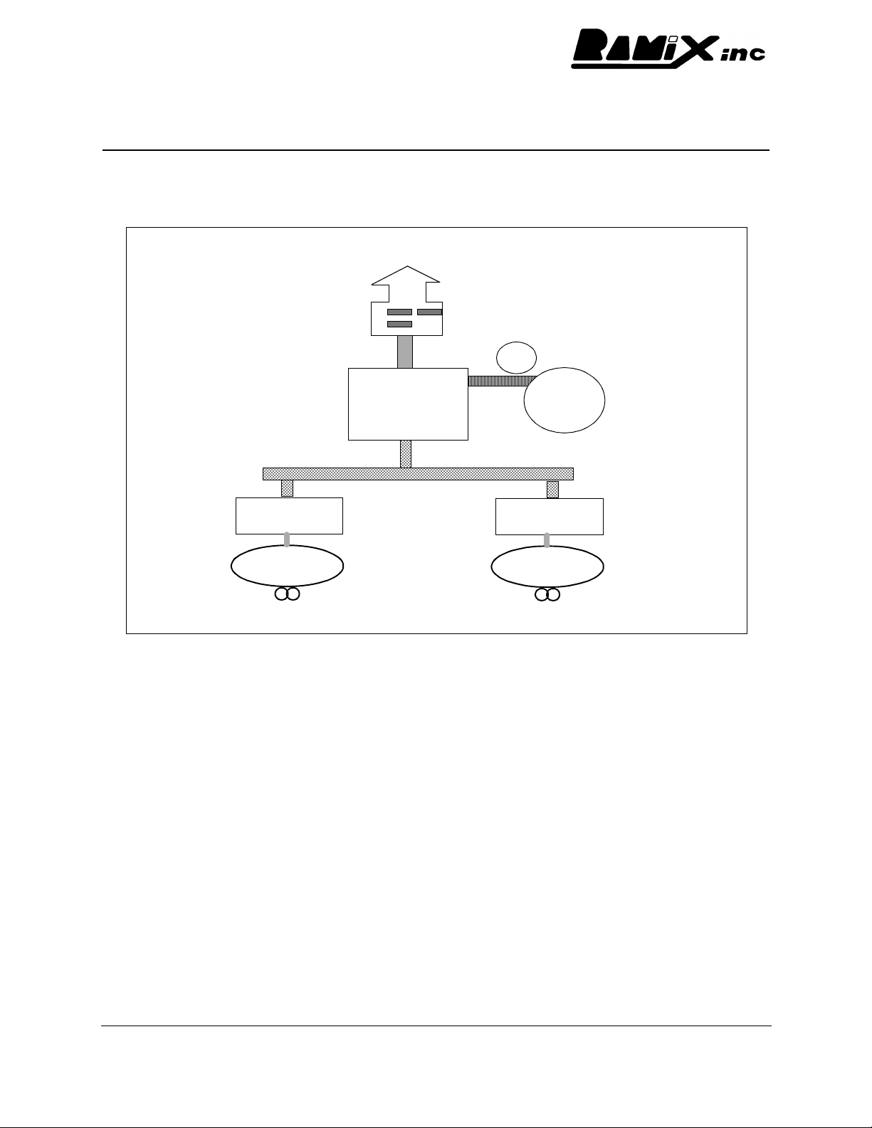
host and co-processor. The PMC665 can be configured such that the:
• bridge/co-processor functions primarily as a bridge, with control local to the host
• with one Ethernet under control of the host, the other by the co-processor or
• with all low level control resident in the co-processor
How the PMC665 responds to PCI configuration requests from the host can be altered by on-
board firmware. Upon power-up (or reset), the on-board processor performs a Built-In-Test (BIT)
sequence of the internal (Bridge/co-processor) operation, local memory subsystem and Ethernet
controllers. Results are available to the host via configuration registers. During the BIT, the co-
processor loads firmware from the FLASH device. It is this firmware that controls how the
PMC665 behaves in relationship to the host and the Ethernet interfaces. The on-board FLASH is
512Kbytes; 128Kbyte is reserved for customer-specific configuration parameters. It is possible to
update the FLASH contents either from the host, or (with appropriate on-board firmware loaded)
over the Ethernet.
The switch is set at the factory for different modes of operations: with processor enabled or
disabled. If enabled, the processor will load firmware from on card flash and begin execution. If
Disabled, the processor will be held in reset. In this condition the PCI bridge functions remain
operational, the PMC665 can be treated as an unintelligent dual network card.
3.0.4 Ethernet Controllers
The Ethernet Controllers on the PMC665 have enjoyed several years of active evolution, featuring
improvements at both the PCI bus and Ethernet interface. Each controller is a fully independent
unit, with local FIFO buffers to decouple PCI and Ethernet activity. Decoupling the Ethernet and
PCI ensures that data transfers will meet the timing requirements of each transaction (which is of
particular importance on the Ethernet) regardless of the loading on the other bus interface. These
FIFO buffers are sufficiently deep to support good burst transfers and presenting minimum
overhead to the PCI bus. When doing data transfer on the PCI bus the Ethernet DMA engine will
attempt to maximize the length of burst transactions, which is critical to obtain the potential
bandwidth of the PCI protocol. These properties allow sustained full bandwidth transfers on both
Ethernet ports.
3.0.5 Fiber Connections
The PMC665 uses two Dual Transceivers with SC style connectors, and PMC665A uses the ST
style connectors. The Transceivers are fully compliant with the standards defined by the Feast
Artisan Technology Group - Quality Instrumentation ... Guaranteed | (888) 88-SOURCE | www.artisantg.com

Rx-URME-007 Rev - -2 - Preliminary - PMC665 Hardware Reference and Installation Manual Page 8
Ethernet Alliance for 100 Base-FX (which is identical to the FDDI PMD standard - ANSI X.3.166).
The Transceivers are rated for 2000 meter multi-mode fiber cabling.
3.0.6 Control and Data Flow
From the description of the Bridge/co-processor, it will be apparent that control of the Ethernet
interfaces can be either by the host, or the co-processor. This decision can be made on a per-
interface basis. When control is resident in the co-processor, the Ethernet interface is not
detected (or accessible) to the host processor. Data can be transferred between the Ethernet
interface and either the local DRAM buffer or the host PCI bus. Which is appropriate depends
upon the functional requirements to be implemented by the firmware. Allowing data to move
directly from host PCI (and by inference the host memory system) to the Ethernet can reduce
transfer latencies.
Note: (Direct data transfer is not a requirement for sustaining maximum performance. The 100+
Mbytes per second bandwidth of each of the busses on the PMC665, combined with their
independent operation provides substantial margin in store (filter) and forward operations.
Thus, implementing sophisticated translation, filtering response or fail-over with the co-
processor does not compromise full Ethernet performance).
3.1 Switch Control (SW1)
SW1 controls the initialization status of the on-card processor. It should not be altered from the
factory default which will have been set appropriatly for the ordered configuration. (Processor
Enabled if firmware was specified, Disabled if no firmware was specified)
Switch
Number Enable
Processor Disable
Processor
1Open Open
2Open Open
3Open CLOSED
4Open CLOSED
Artisan Technology Group - Quality Instrumentation ... Guaranteed | (888) 88-SOURCE | www.artisantg.com

Rx-URME-007 Rev - -2 - Preliminary - PMC665 Hardware Reference and Installation Manual Page 9
4 Front Panel Indicators
PMC665ST
Transmit
Link
Receive
Transmit
Link
Receive
Bottom
Ports
Top Ports
(Primary)
Transmit
Link
Receive
Bottom
Ports
Transmit
Link
Receive
Top Ports
(Primary)
PMC665
RX
PMC665ST/R
1TXRXTX
2
PMC665ST/R
Transmit
Link
Receive
Transmit
Link
Receive
Top Ports
(Primary) Bottom
Ports
Artisan Technology Group - Quality Instrumentation ... Guaranteed | (888) 88-SOURCE | www.artisantg.com

Rx-URME-007 Rev - -2 - Preliminary - PMC665 Hardware Reference and Installation Manual Page 10
5 Specifications
5.1 General
5.1.1 General specifications for PMC665 are listed below.
CHARACTERISTICS SPECIFICATIONS
100 Mbit Fiber Ethernet 100BaseFx
Connector Dual SC Package ANSI X.3166-1990
Compatibility IEEE1386, IEEE802.3, ANSI 8802-3
Interface PCI Revision 2.1
Size IEEE1386, Standard Single PMC
Drivers VxWorks,pSOS,Lynx, Digital UNIX,
Windows NT. (Contact RAMiX for additional
software support information)
Temperature
Operating
Storage 0°C to 60°C
-40°C to 85°C
Power Requirements
Power Max.
Power Max. 1.5A @ 3.3V, typical 1.3A @ 3.3V
300mA @ 5V, typical 210mA @ 5V
Artisan Technology Group - Quality Instrumentation ... Guaranteed | (888) 88-SOURCE | www.artisantg.com

Artisan Technology Group is your source for quality
new and certied-used/pre-owned equipment
• FAST SHIPPING AND
DELIVERY
• TENS OF THOUSANDS OF
IN-STOCK ITEMS
• EQUIPMENT DEMOS
• HUNDREDS OF
MANUFACTURERS
SUPPORTED
• LEASING/MONTHLY
RENTALS
• ITAR CERTIFIED
SECURE ASSET SOLUTIONS
SERVICE CENTER REPAIRS
Experienced engineers and technicians on staff
at our full-service, in-house repair center
WE BUY USED EQUIPMENT
Sell your excess, underutilized, and idle used equipment
We also offer credit for buy-backs and trade-ins
www.artisantg.com/WeBuyEquipment
REMOTE INSPECTION
Remotely inspect equipment before purchasing with
our interactive website at www.instraview.com
LOOKING FOR MORE INFORMATION?
Visit us on the web at www.artisantg.com for more
information on price quotations, drivers, technical
specications, manuals, and documentation
Contact us: (888) 88-SOURCE | sales@artisantg.com | www.artisantg.com
SM
View
Instra
Table of contents
Other Ramix Recording Equipment manuals