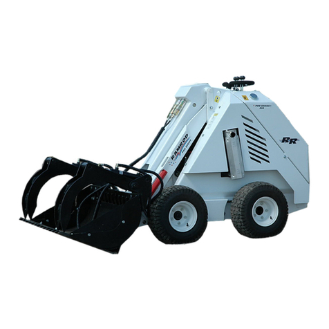
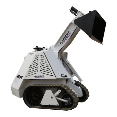
RAMROD ESTATE 500 User manual

________________________________________________
MINI SKID LOADER
MODEL 500 & 575T “ESTATE SERIES”
________________________________________________
OPERATOR’S MANUAL
________________________________________________
RAMROD Equipment
(A Division of Leon’s Mfg. Company Inc.)
Canada
P.O. Box 5002
135 York Road East
Yorkton, Saskatchewan
S3N 3Z4
Phone: (800) 667-1581
Fax: (306) 782-1884
Email: [email protected]
Website: www.ramrodequip.com
Rev. SEPT 2018


INTRODUCTION
TO OUR CUSTOMER:
RAMROD EQUIPMENT is pleased that you have chosen a RAMROD MINI-SKID.
This loader is a simple, compact power source designed and manufactured to give you years of
dependable service.
Read this Manual carefully before operating the Mini-Skid. It contains the necessary
information for safe and proper operating, routine servicing and preventive maintenance.
We also recommend that you carefully read the Engine Manufacturer’s Manual before operating
the Mini-Skid. Do not neglect the maintenance that is recommended.
The reference to right-hand and left-hand used throughout this Manual refers to the position
when operating the machine, facing forward.
For any additional information required, please refer to your RAMROD Dealer.
© Copyright 2008, Ramrod Equipment Corporation
All rights reserved.
No part of this book may be reproduced or transmitted by any means, electronic or mechanical,
including photocopying, recording or by any information storage and retrieval system, without
written permission of Ramrod Equipment Corporation.
August 2011
Printed in Canada
RAMROD EQUIPMENT
(A Division of Leon’s Mfg. Company Inc.)
CANADA
Box 5002 –135 York Road East
Yorkton, Saskatchewan
S3N 3Z4
Phone: (800) 667-1581
Fax: (306) 782-1884
Email: sales@ramrodequip.com
Website: www.ramrodequip.com

RAMROD WARRANTY
The RAMROD EQUIPMENT warrants each new RAMROD Mini-Skid to be free from proven
defects in material and workmanship under normal use and maintenance for a period of twelve
(12) months, commencing with delivery to the original buyer. Under conditions of this warranty,
the Mini-Skid must be operated according to manufacturer’s instructions, and by a competent
and careful operator.
This warranty shall not apply to the Mini-Skid on any part thereof, which has been subject to
misuse, negligence, alteration, accident, or used in any way, which, in the manufacturer’s option,
adversely affects its performance.
It is the responsibility of the Buyer, at his expense, to transport the Mini-Skid or any part thereof
in fulfilling this warranty to a designated service shop.
In no event shall the Buyer be entitled to recover for incidental or consequential damages such
as, but not limited to, rental of replacement equipment, loss of profits, and loss of Mini-Skid
fluids and lubricants.
This warranty does not extend to Mini-Skid components such as, but not limited to, engine, tires,
batteries, hydraulic/hydrostatic components which are manufactured by others, and which carry
separate warranties of their respective manufacturer’s.
This warranty is in lieu of all other warranty expressed or implied, and there are no warranties of
merchantability or fitness for a particular purpose.
No representative of the manufacturer, nor the selling dealer has authority to change this
warranty in any manner whatsoever.
Printed in Canada
NOTE: In order for warranty to be in effect, the following warranty
registration forms must be completed and one copy sent to Ramrod
Equipment at time of sale.
Leon's Mfg. Company Inc.
“Home of Quality Leon & Ramrod Products”
Leon's Mfg. Company Inc.
PO Box 5002, 135 York Road East, Yorkton, SK S3N 3Z4 Canada
Ph: 306.786.2600 Fax: 306.782.1884
www.leonsmfg.com www.ramrodequip.com www.lrattachments.com
RAMROD MINI-SKID LOADER
DEALER PRE-DELIVERY INSPECTION & SERVICE REPORT
Owner: Dealer:
Address: Address:
Model: Serial No: Date:
Engine Serial No: Hour Meter Reading:
Item Remarks
( ) Check engine oil
( ) Check hydraulic oil level
( ) Check radiator coolant level
( ) Check battery fluid level
( ) Check tension of engine belts
( ) Check air cleaner hoses & connections
( ) Grease/lubricate all pivot points
( ) Grease/lubricate control lever cross
shafts and linkages
( ) Check all wheel bolts for tightness
(90 ft-lbs)
( ) Check tire pressure
( ) Check drive chain adjustment
( ) Check for loose or missing bolts, nuts,
cotter pins etc.


RAMROD EQUIPMENT
NEW MINI-SKID WARRANTY REGISTRATION FORM
_____________________ __________________ _____________________
Mini-Skid Serial Number Model Number Engine Serial
Number
________________________________ _______________________________
Name of Owner Name of Dealer
________________________________
Owner’s Type of Business
________________________________ _______________________________
Owners Address Dealers Address
________________________________ _______________________________
Date Mini-Skid Sold Date Mini-Skid Delivered
OPTIONS & ACCESSORIES
RAMROD COPY
Please forward to:
RAMROD EQUIPMENT
P.O. Box 5002, 135 York Road East
Yorkton, Saskatchewan, Canada
S3N 3Z4
Phone: (800) 667-1581
Fax: (306) 782-1884
BUCKETS:
□31 inch (787mm)
□36 inch (914mm)
□42 inch (1067mm)
TIRES:
□4” Tires (30” Wide)
□8” Tires (30” Wide)
□6” Tracks (34” Wide)
□9” Tracks (40” Wide)


P.O. Box 5002, 135 York Road East
Yorkton, Saskatchewan, Canada
S3N 3Z4
Phone: (800) 667-1581
Fax: (306) 782-1884
RAMROD EQUIPMENT
NEW MINI-SKID WARRANTY REGISTRATION FORM
_____________________ __________________ _____________________
Mini-Skid Serial Number Model Number Engine Serial
Number
________________________________ _______________________________
Name of Owner Name of Dealer
________________________________
Owner’s Type of Business
________________________________ _______________________________
Owners Address Dealers Address
________________________________ _______________________________
Date Mini-Skid Sold Date Mini-Skid Delivered
OPTIONS & ACCESSORIES
DEALER COPY
BUCKETS:
□31 inch (787mm)
□36 inch (914mm)
□42 inch (1067mm)
TIRES:
□4” Tires (30” Wide)
□8” Tires (30” Wide)
□6” Tracks (34” Wide)
□9” Tracks (40” Wide)

10

11
P.O. Box 5002, 135 York Road East
Yorkton, Saskatchewan, Canada
S3N 3Z4
Phone: (800) 667-1581
Fax: (306) 782-1884
RAMROD EQUIPMENT
NEW MINI-SKID WARRANTY REGISTRATION FORM
_____________________ __________________ _____________________
Mini-Skid Serial Number Model Number Engine Serial
Number
________________________________ _______________________________
Name of Owner Name of Dealer
________________________________
Owner’s Type of Business
________________________________ _______________________________
Owners Address Dealers Address
________________________________ _______________________________
Date Mini-Skid Sold Date Mini-Skid Delivered
OPTIONS & ACCESSORIES
CUSTOMER COPY
BUCKETS:
□31 inch (787mm)
□36 inch (914mm)
□42 inch (1067mm)
TIRES:
□4” Tires (30” Wide)
□8” Tires (30” Wide)
□6” Tracks (34” Wide)
□9” Tracks (40” Wide)


1
TABLE OF CONTENTS
I. SAFETY........................................................................................................................ 2
Safety Precautions........................................................................................................... 2
II CONTROL.................................................................................................................... 4
Engine Controls –Briggs 13.5 HP Gasoline .................................................................. 4
Primary Controls............................................................................................................. 6
Attachment Lock Pins..................................................................................................... 8
III OPERATION............................................................................................................... 9
Pre-Starting Inspection and Preperation ......................................................................... 9
Starting Procedure –Gasoline Engine............................................................................ 9
Shut-Off Procedure –Gasoline Engine......................................................................... 10
Mounting Attachments.................................................................................................. 11
Operational Procedure .................................................................................................. 12
IV MAINTENANCE ...................................................................................................... 16
Engine Maintenance –Briggs Engine........................................................................... 16
Battery Maintenance..................................................................................................... 17
Air Filter Maintenance.................................................................................................. 17
Fuels, Lubricants and Capacities .................................................................................. 18
Hydraulic System Maintenance.................................................................................... 19
Final Drive Maintenance............................................................................................... 20
Chain Lubrication ......................................................................................................... 21
Periodic Greasing Details ............................................................................................. 22
Periodic Maintenance and Service Schedule................................................................ 23
Troubleshooting............................................................................................................ 24

2
I. SAFETY
OPERATE MINI-SKID SAFELY
IMPROPER OPERATION OF THIS MINI-SKID MAY RESULT IN SERIOUS INJURY.
BEFORE OPERATING THIS MINI-SKID, OPERATORS MUST HAVE PROPER
INSTRUCTIONS, BE FAMILIAR WITH THE SAFETY PRECAUTIONS, AND HAVE READ
THIS AND THE ENGINE MANUFACTURER’S MANUAL THOROUGHLY.
THIS SAFETY ALERT SYMBOL
POINTS OUT IMPORTANT
SAFETY PRECAUTIONS.
OPERATORS MUST UNDERSTAND CAPABILITIES AND LIMITATIONS OF THE EQUIPMENT,
WITH RESPECT TO SPEED, BRAKING, STEERING, STABILITY AND LOAD CHARACTERISTICS
BEFORE STARTING TO OPERATE.
NEW OPERATORS MUST CHECK ALL CONTROLS IN A SAFE, OPEN AREA BEFORE STARTING
WORK.
WARNING
This Decal Advised Of Actions or
Danger Which Can Cause
Personal Injury.
Wear Ear Protection
When Engine Is Running.
The Sound Pressure
Level Is: 102 DB for A
Weighted level & 88 DB
For C Weighted Level…
IMPORTANT
This Decal Identifies Procedures
Which Must Be Followed to
Prevent Damage To The
Mini-Skid
Do Not Use the Mini-Skid
During A Thunderstorm
Or When There Is A
Chance of a Lightning
Strike.
SAFETY PRECAUTIONS
READ YOUR OWNERS’S MANUAL AND ALL SUPPLEMENTS BEFORE OPERATING YOUR
MINI-SKID.
WHEN LEARNING TO OPERATE, PROCEED SLOWLY AND CAREFULLY.
DO NOT PLACE FEET UNDER THE PLATFORM.
DO NOT OPERATE ANY OF THE CONTROL LEVERS INCLUDING AUXILIARY POWER TAKE-
0FF UNLESS YOU ARE STANDING WITH BOTH FEET ON THE PLATFORM AND FIRMLY
HOLDING THE GRIP HANDLES.
DO NOT JERK THE CONTROL LEVERS, USE A STEADY EVEN MOTION.

3
SAFETY
SAFETY PRECAUTIONS –CONTINUED
KEEP HANDS, FEET AND CLOTHING AWAY FROM ALL MOVING PARTS AND CYLINDERS.
DO NOT ALLOW ANY ONE TO RIDE IN BUCKET.
DO NOT ALLOW MORE THAN ONE PERSON ON THE MINI-SKID AT ANY TIME.
DO NOT ALLOW ANY OTHER PERSON OR ANIMAL CLOSE TO THE MINI-SKID WHILE IN OPERATION.
WATCH FOR OTHER PEOPLE AND EQUIPMENT.
KEEP THE BUCKET LOW WHEN TRAVELLING, TURNING OR CHANGING SPEED.
TRAVEL SLOWLY OVER ROUGH TERRAIN.
BEWARE OF TRENCHES, HOLES AND SIDE SLOPES
DO NOT DRIVE THE MINI-SKID ACROSS STEEP SLOPES.
LOAD, UNLOAD AND TURN AROUND ON FLAT, LEVEL GROUND ONLY.
ENSURE ADEQUATE VENTILATION WHEN USING THE MACHINE IN CONFINED SPACES.
DO NOT CARRY LOAD WITH ARMS IN A RAISED POSITION. ALWAYS CARRY LOADS CLOSE TO THE
GROUND. DO NOT STEP OFF PLATFORM WITH THE LOAD RAISED.
TO AVOID FREE-FALL OF LOAD WHEN LOWERING LIFT ARMS, DO NOT PUSH LIFT ARM LEVER
FULLY FORWARD.
DO NOT EXCEED RATED LOAD CAPACITY.
ALWAYS LOWER THE BUCKET AND SHUT OFF THE ENGINE BEFORE LEAVING THE MACHINE.
AVOID PARKING ON A SLOPE. IF IT IS NECESSARY, PARK ACROSS THE GRADE, GROUND THE
BUCKET AND BLOCK THE WHEELS.
WHEN HOOKING UP ATTACHMENTS TO THE MACHINE, CHECK TO BE SURE LOCK PINS ARE FULLY
ENGAGED.
DO NOT PLACE ANY PART OF THE OPERATOR’S BODY OR ALLOW ANYONE UNDER MINI-SKID ARMS
OR ATTACHMENTS.
DO NOT LUBRICATE, ADJUST OR REPAIR THE MACHINE WITH THE ENGINE RUNNING.
NEVER FUEL A HOT MACHINE.
DO NOT SMOKE WHEN FUELING OR OPERATING THE MACHINE.
ALWAYS READ THE OWNER’S MANUAL FOR PROCEDURES FOR SERVICING AND MAINTENANCE OF
THE MINI-SKID.
REMEMBER, SAFETY FIRST.

4
II CONTROL
It is necessary to become familiar with the location and purpose of each control before
operating the Mini-Skid.
ENGINE CONTROLS –BRIGGS 13.5 HP GASOLINE
Figure 1: Briggs Instrument Panel
Throttle Control –When the Throttle
control lever is pushed fully up the
engine is at “idle”. Pushing the control
down will increase the engine speed.
The lever will catch at fast and pushing
it down all the way operates the choke.
For Throttle positions see Figure 1A-1C.
Ignition Switch –The ignition switch is
a three-position switch. Clockwise from
the OFF position is the ON and start
position.
IMPORTANT
Be Sure Ignition Key Is In Off Position,
Or Even Removed, When The Engine Is
Not Running
IMPORTANT
For Maximum Power While Working,
The Engine Should Be Running At Full
Throttle
Ignition Switch
Throttle Control

5
II CONTROL
Throttle Control Positions
Figure 1A: Idle
Figure 1B: Fast
Figure 1C: Choke

6
II CONTROL
Figure 3: Control Panel
PRIMARY CONTROLS
1. Lift Arm Lever
2. Tilt Lever
3. Auxiliary Lever
4. Left Hand Drive Lever
5. Right Hand Drive Lever
6. Grip Handle
DRIVE LEVERS, Item 4 & 5 Figure 1
The left hand drive lever controls the
wheels on the left hand side and the right
hand drive lever controls the wheels on the
right hand side.
Engage the drive levers slowly because
even a small movement of the levers will
cause motion. All lever movements
should be smooth and gradual. To drive
the Mini-Skid straightforward, move both
control levers forward the same amount.
To drive the Mini-Skid Straight backward,
move control levers back the same
amount.
The Mini-Skid is steered by moving one
lever further forward than the other. To
turn left, move the right lever further
ahead than the left lever; to turn right,
move the left lever further ahead than the
right lever. For the Mini-skid to perform a
spin-turn, or “Skid Steer”, move one lever
forward and the other backward the same
amount.
The “TASKMASTER” features single-
handed steering. For normal operation,
the most comfortable hand position is to
operate the two steering levers with the
Figure 4: Single Hand Steering
palm of the right hand, with the fingers
gripping the grip handle. Flexing the
fingers will allow forward travel, and
simply rotating the palm will allow
normal steering. To reverse, slip the
palm back to the rear of the grip handle,
and use the tips of the fingers to pull the
steering levers backwards.
This position will allow for more precise
control of the unit. At the same time, the
left hand should grip the grip handle for
operator stability, but can also be used to
operate the tilt and dump functions as
required.
NOTE: Be sure to slowly move the
levers to the center (neutral) position
when stopping. The Mini-Skid will stop
INSTANTLY if the operator releases the
drive levers.
Warning
Do Not Move Any Of The Control Levers
Unless Standing With Both Feet On The
Platform And Holding The Grip Handles
1
2
3
4
5
6

7
II CONTROL
Warning
Keep BOTH HANDS On The Grip
Handle At All Times When Operating
The Machine.
Warning
Use Extreme Caution When Stopping. If
The Bucket Or Attachments Is Raised,
The Machine Can Tip.
Keep All Movements Smooth. All New
Operators Must Work The Machine In A
Safe Open Area To Become Familiar
With Its Operating Characteristics.
LIFT CONTROL LEVER –Item 1,
Figure 3
The outside control lever located on the
left hand side controls the lift. Pushing
the lever forward lowers the lift arm and
pulling the lever back raises the lift arm.
In these two positions, the lever is spring
centered to neutral upon release of the
lever.
TILT CONTROL LEVER –Item 2,
Figure 3
The inside control lever located on the
left hand side controls the tilting action
of attachments such as buckets, forks,
etc. Pulling the lever back tilts the
attachments back. Pushing forward on
the lever tilts forward or “dumps” the
attachment. The lever is spring centered
to neutral upon release.
IMPORTANT
Ensure That The Auxiliary Lever Is Kept
In Neutral When Not Being Used To
Avoid Wasting Power. Engine Is
Difficult To Start If Lever Is Engaged.
Hydraulic Oil May Also Overheat
AUXILIARY LEVER –Item 3,
Figure 3
Direction of auxiliary flow and “on-off”
control of attachments is provided by
this lever. When the auxiliary controls
above are turned on, this lever becomes
active. Pushing this lever forward will
operate the attachment in one direction,
while pulling it back will operate the
attachment in the opposite direction.
This lever locks in each position and
must be returned to the center (off)
position manually.

8
II CONTROL
ATTACHMENT LOCK PINS
The “Taskmaster: tool bar design allows
changing from one attachment to another
quickly and easily, without having to
remove pins.
Attachments are secured on the unit with
two spring-loaded pins. Rotating the
handles on the pins one half of a turn
moves the pins from the locked to the
unlocked position.
To unlock attachments, rotate both pins
so that their handles are both pointing to
the outside of the tool bar, as show in
Figure 5.
To lock attachments, rotate both pins
inwards so that both handles are pointing
towards the center of the machine as
shown in Figure 6. This will allow the
springs to push the pins downwards
through the mounting holes in the
attachment and secure it to the unit.
WARNING
The design of the quick attach system is such that
attachments can be lifted and carried without the
lock pins being engaged. Before using any
attachment, check to be sure that the lock pins
are fully engaged and properly in place. The
attachment will fall off when dumped if the lock
pins are not engaged, resulting in possible
damage or injury.
Figure 5 (Lock Pins Disengaged)
Figure 6 (Lock Pins Engaged)
WARNING
After Hook-Up To Attachment, Check To
Be Sure Lock Pins Are Fully Engaged,
And Locked Into Position.
This manual suits for next models
1
Table of contents
Other RAMROD Compact Loader manuals

RAMROD
RAMROD 3300 User manual

RAMROD
RAMROD 930 User manual

RAMROD
RAMROD 905 User manual

RAMROD
RAMROD TASKMASTER 1350 PRO Series User manual

RAMROD
RAMROD PRO 1330 User manual

RAMROD
RAMROD MINI SKID TASKMASTER Series User manual

RAMROD
RAMROD WB1630TX User manual

RAMROD
RAMROD 950 User manual

RAMROD
RAMROD 930 User manual