2
RAMTECHGLOBAL.COM
Contents
Introduction .............................................................................................................................................................................................................................
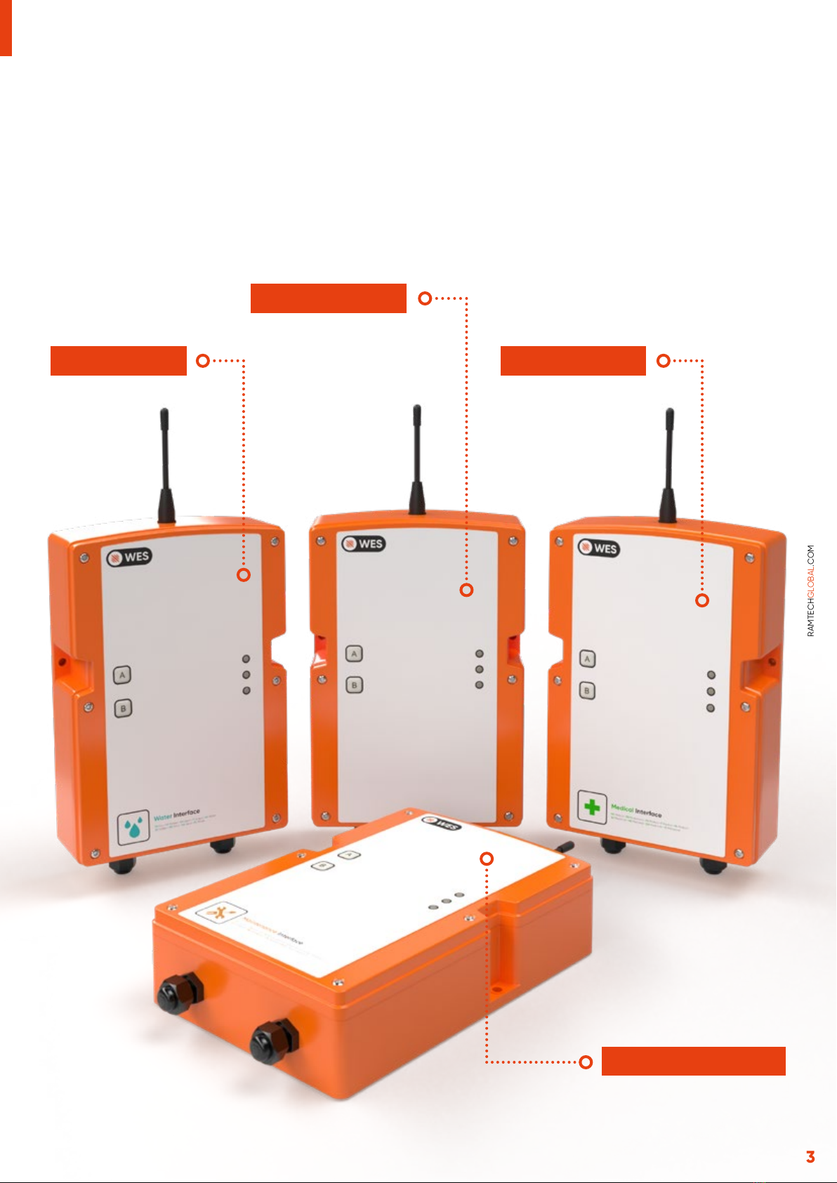
WES3 Standard Interface ...................................................................................................................................................................................................
WES3 Water Interface .........................................................................................................................................................................................................
WES3 Medical Interface ......................................................................................................................................................................................................
WES3 Maintenance Interface ...........................................................................................................................................................................................
General Installation ..............................................................................................................................................................................................................
WES3 Standard Interface ...................................................................................................................................................................................................
LED Indications ......................................................................................................................................................................................................................
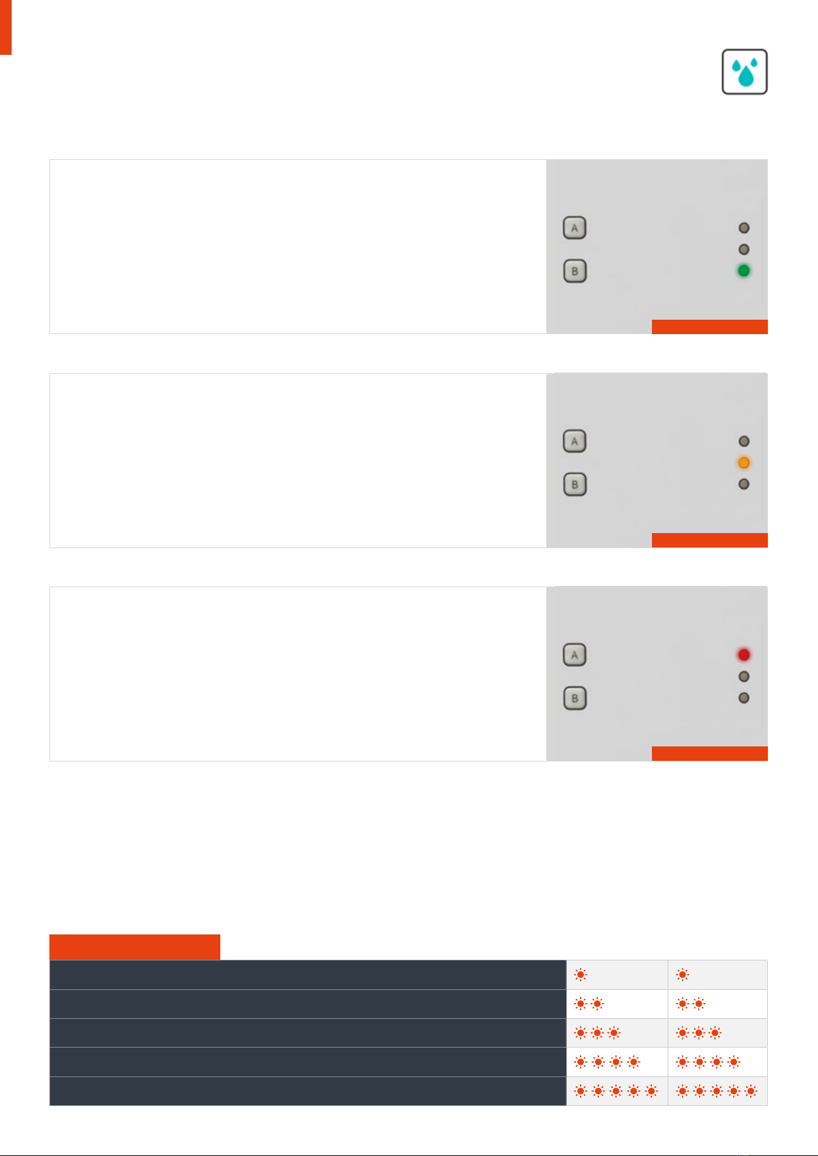
WES3 Water Interface .........................................................................................................................................................................................................
Installation recommendations ..........................................................................................................................................................................................
LED Indications ......................................................................................................................................................................................................................
Scenarios .................................................................................................................................................................................................................................
WES3 Medical Interface ......................................................................................................................................................................................................
LED Indications ......................................................................................................................................................................................................................
WES3 Maintenance Interface ............................................................................................................................................................................................
LED Indications ......................................................................................................................................................................................................................
4
4
4
4
4
5
6
7
8
9
10
11
12
13
14
15
Device Parameters
Dimensions (mm) HxWxD: 235 x 161 x 58 (excl. Antenna 81mm and USB 15mm)
Weight: 1.4kg
Operating temperature: -25°C to +70°C
Supply Parameters
Operating voltage range: 4.4-6.4V from internal battery
Current consumption: 120μA average
Battery type: Alkaline primary cells, 23Ah
RF Parameters
Operating frequency: 916.5 MHz
Transmit power: 25mW max
Duty cycle: <1%
Technical Data