Ensemble Designs Avenue 8400 Series User manual

This data pack provides detailed installation, configuration and operation information for
the 8400 Series Video Processing Synchronizer module along with the 8410,8415,
and 8510 Audio Processing and 8520 DNR option submodules as part of the Avenue
Signal Integration System.
The module information in this data pack is organized into the following sections:
• 8400 Series Overview
• Applications
• Installation
°Configuring Rear BNCs
• Cabling
• Module Configuration and Control
°Front Panel Controls and Indicators
°Avenue PC Remote Control
°Avenue Touch Screen Remote Control
• Troubleshooting
• Software Updating
• Warranty and Factory Service
• Specifications
8400-1
Model 8400 Series
Video and Audio
Processing
Data Pack
Revision 4.1SW v2.2.6
ENSEMBLE
DESIGNS

8400 SERIES OVERVIEW
The 8400 Video Processing Frame Synchronizer, along with its optional submodules, is a
real "do it all" module, it’s the total solution for digital video and digital audio processing.
Uncompromising attention to image quality and fidelity means that it does what you need
and keeps your signals pristine.
The 8400 has SDI I/O with a rugged frame synchronizer and a powerful proc amp. An
infinitely adjustable timing system genlocks to your house reference. Optional Audio
Processors and an optional Digital Noise Reducer round out the 8400 module.
The SDI input is carried at full uncompressed bandwidth throughout the entire module,
and EDH monitoring of the digital input alerts you to any incoming problem. Complete
control over signal levels is provided. Input video is synchronized to your house reference
by the 8400’s built-in Frame Synchronizer.
The 8400 has a full-featured Proc Amp for adjustment of every signal parameter. Proc
controls include Video and Chroma Gain, NTSC style hue rotation, Black Balance, and
pedestal. Black and White clips can be set to prevent excessive signal excursions. To help
optimize the settings in the Proc Amp, a Split Screen mode allows you to compare the
processed output with the original material.
A Detail Enhancer recovers information that has been lost due to poor frequency response
in upstream systems. Certain values represented in serial digital component may be
illegal in the NTSC or PAL composite domains. The Predictive Composite Clipper mode
identifies picture elements that would be illegal in analog composite, and limits color
saturation and luminance excursions. Work done in digital component will look its best
when viewed in composite. Selective (toothed) vertical blanking lets you choose to pass or
strip content in the vertical interval on a line by line and field by field basis.
The 8520 Digital Video Noise Reducer (DNR) is an optional sub module that can be added
to the 8400 Video Processing Frame Synchronizer. The noise reduction process is
downstream of the 8400 Proc Amp controls. It only adds 4 microseconds to the throughput
delay of the 8400, so it does not introduce problems with system timing. The 8520 DNR is
motion and scene adaptive. It removes unwanted noise and artifacts, making it perfect for
MPEG compression preprocessing and satellite or ENG feeds.
Several forms of noise reduction are employed to ensure the best possible performance.
Recursive Temporal Noise filtering includes Simple Recursive, Motion Adaptive and
Motion Adaptive with Impulse filter. Controls are provided for maximum signal to noise
improvement and for noise threshold. They can be set manually or run in automatic mode.
Because the 8400 is an Avenue module, every function and parameter can be controlled
from an Avenue Touch Screen, Express Control Panel, or the Avenue PC Control
Application. While it can be used to control any Avenue module, the Express Panel really
shines when used with the 8400 Signal Acquisition system modules. With dedicated
video,chroma, pedestal, and hue knobs, live shading is easy. The continuous rotation
velocity sensitive knobs are responsive and dependable. Audio levels for multiple groups
are easily accessed as well. All other parameters, including timing and audio delay, are
accessed through an intuitive menu interface.
8400 module memory registers can be used to save the complete configuration of the
module, making it easy to change instantly between different configurations.
Model 8400 Series Modules
8400-2

Modules at software version 2.2.0 or later support SNMP (Simple Network Management
Protocol) monitoring. For each applicable signal processing module, module, signal, and
reference status are reported. For complete details on using SNMP monitoring, refer to
the Avenue System Overview in the manual that accompanies each frame.
One of three types of Audio Processing submodules can be installed on the 8400 module.
The audio processors have also been designed to provide superior handling of embedded
audio. The disembedder on the input side follows the timing of the SDI input, even if that
input is asynchronous to the house reference. The embedder on the output side is syn-
chronous to house. This allows embedded audio to be safely bypassed around the video
Framestore with the lip sync properly preserved. Embedded audio content is properly re-
synchronized. The audio processors have built in sample rate conversion allowing usage of
asynchronous AES inputs. Synchronous AC-3 or Dolby-E audio signals may also be used.
The 8410 4 Channel Audio Processor shown in the block diagram below is a submodule
with flexible architecture that addresses a wide range of audio handling needs. The
submodule accepts two external AES audio inputs and one embedded audio group from
the SDI video input. Two outputs can be routed to the AES outputs while four outputs can
also be embedded into the SDI output signal.
8400 Series Functional Block Diagram with 8410 and 8420 Options
Model 8400 Series Modules
8400-3

Model 8400 Series Modules
The 8415 Audio Processor submodule shown below provides eight channels of digital
audio processing. Digital audio inputs to the 8415 can come from four AES ports and/or
disembedded from the 601 SDI input stream. After processing, digital outputs in both AES
and embedded form are possible.
There are four AES ports, using the four AES BNC connectors on the rear of the chassis.
When an 8415 is installed, these BNCs become bi-directional ports. Each of them can
either be an AES input or an AES output. These four AES ports are associated with pairs
of channels: Ch 1/2, Ch 3/4, Ch 5/6, and Ch 7/8. A port will become an output if it has not
been chosen as an AES input in the Aud In A and Bmenus.
There are two disembedders on the input side of the 8415 referred to as A and B. These
disembedders are being fed the 601 SDI video input stream in parallel and each of them
can be independently targeted to any of the four possible groups. The A disembedder will
produce two pairs of audio signals, referred to as SDI 1/2 and SDI 3/4.
The B disembedder will also produce two pairs of audio signals referred to as SDI 5/6 and
SDI 7/8. In the B disembedder, the SDI 5/6 pair corresponds to the first and second
channels in the selected group and SDI 7/8 is taken from the third and fourth channels in
that group.
The disembedded audio can then be processed with level adjustment, channel mixing,
shuffling, and automatic tracking of the delay imposed on the video channel. It can then
be embedded into the video signal downstream of the the frame synchronizer, proc amp,
and DNR functions on the 8400 module.
There are two embedders referred to as A and B to support the eight channels of audio,
one for each group. The embedders are placed in series with the A embedder first and the
B embedder second. Each embedder must be configured for operating mode and the
desired group (1 – 4) in which to embed the audio.
(Note that using the 8415 requires Ave PC software version 2.0.4 and higher and the
Control module must be running version 2.0.5 or higher. These versions can be download-
ed from the Ensemble website.)
8400-4
CH 1/2
CH 3/4
Dual Audio
Disembed
8415 Audio Processor Option
Source Selection
Level Adjust
Swap & Shuffle
Channel Mixing
AES Inputs
Digital
Signal Processing
Ch 5/6
Ch 7/8
Audio
Embed
Output
Routing
Auto
Tracking
Audio
Delay
A A B
To 8500 SDI Out
From 8500 SDI In
B
CH 5/6
CH 7/8
AES Outputs
SDI/AES
1/2 Out
SDI/AES
3/4 Out
Switch S4
Switch S5
8415 Audio Submodule Block Diagram

Model 8400 Series Modules
The configuration parameters for the embedders in the Audio Out menu are not identical.
There is no Replace All function for the B embedder as this function occurs in the
upstream embedder A.
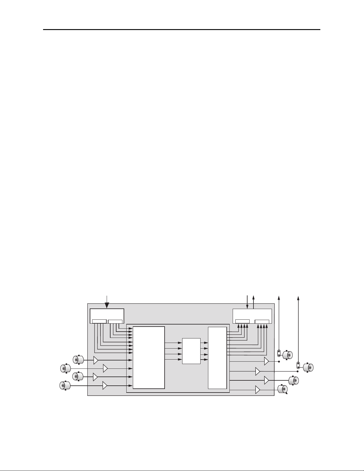
The 8510 4 Channel Audio Processor submodule shown below does everything the
8410 does, plus it provides analog audio audio I/O. The 8510 accepts four channels of
balanced analog audio which are digitized at 24 bits of resolution. Two AES inputs
provide four channels of digital audio to the input selector. Embedded audio (4 channels)
is also available from the SDI input signal. AES audio can be routed to two AES outputs
and embedded into the SDI output signal. Analog audio can be set up for four balanced
inputs, four balanced outputs. or two analog inputs and two analog outputs
There are two BNCs on the rear module that can be configured with onboard switches.
The AES 1/2 and 3/4 outputs (with the 8410 or 8510 submodule installed) can be set inde-
pendently as SDI video or AES outputs. With the 8415 submodule installed, the AES 5/6
and 7/8 outputs can be set independently as SDI video or AES outputs.
8400-5
AES Input
CH 1/2
AES Input
CH 3/4
Analog
Audio I/O
Audio
Disembed
4 Channel
24 Bit
ADC
8510 Audio Processor Option
Source Selection
Level Adjust
Swap & Shuffle
Channel Mixing
Digital
Signal Processing
Audio
Embed
4 Channel
24 Bit
DAC
Output
Routing
Auto
Tracking
Audio
Delay
From 8500 SDI Input To 8500 SDI Output
SDI/AES
1/2 Out
SDI/AES
3/4 Out
Switch S4
Switch S5
8510 Audio Submodule Block Diagram

8400-6
APPLICATIONS
This section provides some typical applications for utilizing the full versatility of the 8400
Video Processor module and the optional submodules, the 8410, 8415, and 8510 Audio
Processor and the 8520 DNR. Configuration of these applications is covered in the
MODULE CONFIGURATION AND CONTROL section later in this manual.
Satellite or Microwave Reception
As illustrated in the block diagram below, the 8400 will accept input from a serial digital
receiver. The SDI input signal will now be locked to house and fully timeable. The 8520
DNR submodule with its Adaptive Motion Detection can be employed to clean up noisy
video.
Proper audio/video timing can be assured when the tracking audio delay of the 8410
Audio Processor is employed. Any timing or delay modifications to the video are tracked
by the 8410 whether you wish to use disembedded audio or audio input from an AES
source. Properly timed audio from any of these sources is available directly when routed
to the AES outputs, or it can be re-embedded back onto the SDI video stream. A fixed
delay of up to 1000mS can be inserted by the 8410 to correct for signals which have previ-
ously passed through frame stores without audio delay compensation.
Model 8400 Series Modules
8400 Video Proc
Frame Sync
8410
Audio Proc
8520
DNR
Digital
Production
Switcher
Production
Audio
Ref
Digital
AES AES
SDI
Satellite
Rcvr
8400 Video Proc
Frame Sync
8410
Audio Proc
Digital
Production
Switcher
Digital
Router
Audio
Console
Ref
SDI
AES
SDI
Microwave
Rcvr SDI
Embedded Audio
Second Language
Audio AES Disembbedded Audio
2nd Language Audio
Both Audios
Reembedded
Satellite or Microwave Application Block Diagram

8400-7
News / ENG Vehicle
News or ENG systems may use a combination of 8400 and 8500 modules. While the 8400
has SDI I/O, the 8500 has SDI, component analog and composite analog I/O. The wide
variety of input feeds often encountered can be easily handled with an Avenue system.
Robust signal handling ensures proper time base correction for nearly any source from a
consumer VHS machine to an unlocked portable camera. Proc Amp functions in the 8400
include video and chroma gain and pedestal, NTSC style hue rotation and a predictive
video signal legalizer. Noisy signals can be cleaned up effectively with the motion and
scene adaptive 8520 DNR. There are operator controls for many choices including
automatic and manual modes. In the manual mode noise reduction factor is adjustable as
is the noise threshold. The show noise and split screen selections allow viewing of effec-
tiveness of your DNR settings.
Audio is ingested by the 8410 or 8510 Audio Processor submodule from analog (8510 only)
or AES sources and/or disembedded from the SDI video stream. The internal four channel
audio mixer/router provides level control, mixing of sources and nearly unlimited swap or
shuffle of channels. The 8400 and all other modules may be monitored and adjusted with
the comprehensive Avenue control system. Graphical interface is utilized with the Avenue
PC application running on a laptop or desktop, while the Avenue Touch Screen with touch
and rotary controls can be simultaneously used.
Model 8400 Series Modules
Tape
Player
Analog
Camera
Digital
Camera
SDI
SDI
embedded
Analog
Helicopter
Feed
Satellite
Downlink
8500 Video Proc
Frame Sync
with
8510 and 8520
8400 Video Proc
Frame Sync
with
8410 and 8520
8500 Video Proc
Frame Sync
with
8510 and 8520
8400 Video Proc
Frame Sync
with
8410 and 8520
8400 Video Proc
Frame Sync
with
8510 and 8520
Analog
SDI
embedded
5440
SDI
8x8
Router
8400 Video Proc
Frame Sync
with
8410 Audio Proc
8400 Video Proc
Frame Sync
with
8410 Audio Proc
8400 Video Proc
Frame Sync
with
8410 Audio Proc
Audio
and
Video
Mixing
and
Routing
8400 Video Proc
Frame Sync
with
8410 Audio Proc
Satellite
Uplink
Ref
5400
Dual TSG Digital and Analog
Test Signals
SDI
embedded
SDI with Embedded Audio SDI with
Embedded Audio
or AES Audio
X-Y Control Panel
PC or Touch Screen Control
of Levels, Inputs, Routing, etc.

Remote Truck/OB Van Operation
A convenient and flexible interconnect to a Remote Truck or OB Van is assured with use of
the 8400 and 8500 Video Processing Frame Synchronizers (shown below). An 8500 input
may be analog component, composite or SDI, timed to house or asynchronous. The 8400
has SDI I/O and is targeted specifically for exclusively digital applications.
Reference is supplied to the 8400 and the output is fully timeable in relation to this
reference. The 8520 DNR submodule has Adaptive Motion Detection and can be employed
to clean up noisy video often found in remote situations.
Using the 8410, AES audio inputs or audio embedded on the SDI stream can be used.
Disembedding and re-embedding of audio to the SDI stream is handled by the 8410 Audio
Processor option submodule. Most any combination of channel shuffle, mixing and gain
riding can also be done. The complete range of mix and level control facilities in the 8410
permit these outputs to be the same as the re-embedded audio, or any other combination
of audio channels.
At the output end of the Remote Truck the 8400 is again used to provide a stable feed to
microwave or fiber.
Video
Tape
Analog
Camera
Digital
Camera
SDI
SDI
embedded
analog
Blimp
Feed
Bright Eye
Fiber Rcvr
with
Frame Sync
8400 Video Proc
Frame Sync
with
8410 and 8520
8500 Video Proc
Frame Sync
with
8510 and 8520
8400 Video Proc
Frame Sync
with
8510 and 8520
8400 Video Proc
Frame Sync
with
8510 and 8520
SDI
SDI
embedded
8400 Video Proc
Frame Sync
with
8410 Audio Proc
Satellite
Uplink
Ref 5400
Dual TSG Digital and Analog
Test Signals
SDI
embedded
PC or Touch Screen Control
of Input Mode, Proc Functions, etc.
Video and Audio
Production Equipment
8400 Video Proc
Frame Sync
with
8410 Audio Proc
SDI Video with
Digital or Embedded Audio
Bright Eye
Fiber Xmtr
with
Frame Sync
Remote Truck/OB Van Application
Model 8400 Series Modules
8400-8

8400-9
Model 8400 Series Modules
INSTALLATION
Rear Module BNC Configuration
There are two configurable rear BNC connectors that can be set using onboard switches
on the rear of the 8400 circuit board for the choices outlined below. AES outputs will
depend on the type of submodule installed. Refer to the illustration on the next page.
• AES 1/2 Out /SDI Out BNC (8410 and 8510 submodule) or AES 5/6/SDI (8415
submodule) Configuration – Switch S4 on the rear of the 8400 circuit board
allows the BNC labeled AES 1/2 Out/SDI or AES 5/6/SDI BNC to output either
AES audio or the processed SDI signal of the module (identical to the other SDI
outputs). Set the toggle switch to AES to configure the BNC for AES out or set to
SDI for the SDI output. The default setting for this switch set at the factory is
AES.
• AES 3/4 Out /SDI Out BNC (8410 and 8510 submodule) or AES 7/8/SDI (8415
submodule) Configuration – Switch S5 on the rear of the 8400 circuit board
allows the BNC labeled AES 3/4 Out/SDI or AES 7/8/SDI BNC to output either
AES audio or the processed SDI signal of the module (identical to the other SDI
outputs). Set the toggle switch to AES to configure the BNC for AES out or set to
SDI for the SDI output. The default setting for this switch is AES.
8410, 8415, or 8510 Audio and 8520 DNR Submodule Installation
The optional 8400 Series submodules install on the component side of the 8400 Video
Processing module circuit board. If the options are ordered with the 8400 module, they
will come already installed.
To install the 8410, 8415, or 8510 audio submodule, locate the three connectors on the left
side of the circuit board as shown below and line the connectors up, checking the
alignment. Press carefully into place to seat the submodule.
To install the 8520 DNR submodule, locate the UP arrows on the circuit board and the
submodule. Line up the submodule with the two connectors, matching the UP arrows and
press carefully to seat the submodule.
8400 Video Processing Module
Plug the 8400 module into any one of the slots in the 1 RU or 3 RU frame and install the
plastic overlay provided onto the corresponding group of rear BNC connectors associated
with the module location. Note that the plastic overlay has an optional adhesive backing
for securing it to the frame. Use of the adhesive backing is only necessary if you would
like the location to be permanent and is not recommended if you need to change module
locations. This module may be hot-swapped (inserted or removed) without powering down
or disturbing performance of the other modules in the system.

CABLING
Refer to the 3 RU and 1 RU Backplane with 8410 and 8510 Audio Submodule or
3 RU and 1 RU Backplane with 8415 Audio Submodule on the following page for
cabling instructions. Note that unless stated otherwise, the 1 RU cabling explanations are
identical to those given in the 3 RU diagram.
Configure the two BNCs as described above and follow the correct cabling procedures
depending on how these switches have been configured.
8410, 8415 or
8510 Audio Processor 8520 DNR
Set toggle switches to configure BNCs on the rear module.
S4 and S5 will depend on the type of audio processor submodule installed.
S4 (8410/8510 — AES 1/2 or SDI) or (8415 — AES 5/6 or SDI)
S5 (8410/8510 — AES 3/4 or SDI) or (8415 — AES 7/8 or SDI) Match arrows on submodule
and circuit board.
AES
SDI
AES
SDI
S5
Configure Rear BNCs and Submodule Installation
Model 8400 Series Modules

1
6
+
+
+
+
-
-
-
-
11
AUD 2 AUD 1
AUD 3
AUD 4
8400-11
3 RU Backplane With 8410 or 8510 Audio Submodule
1 RU Backplane With 8410 or 8510 Audio Submodule
AES 1/2 and 3/4 In – Connect
AES digital audio to the AES 1/2
and AES 3/4 inputs.
SDI Out 1 and 2 – Connect
to SDI destinations.
Model 8400 Series Modules
Ref In – Connect a composite
video input (PAL or NTSC) if you
are using an external reference.
SDI In – Connect an SDI input.
Analog Audio Pinouts
Signal Pins Input Output 2 In/2Out
Aud 1 +, –, G 1, 2, 7 Input 1 Output 1 Input 1
Aud 2 +, –, G 5, 4, 8 Input 2 Output 2 Input 2
Aud 3 +, –, G 11, 12, 9 Input 3 Output 3 Output 1
Aud 4 +, –, G 15, 14, 10 Input 4 Output 4 Output 2
Analog Audio – (8510 only)
Use the Analog Audio 15-pin D
connector for cabling analog
audio inputs or outputs when the
8510 option is installed. Refer to
the pinout diagram and the table
below for cabling information.
AES 3/4 Out or SDI Out –
Set BNC to output AES 3/4 audio
or SDI video with toggle switch S5
on circuit board.
AES 1/2 Out or SDI Out –
Set BNC to output AES 1/2 audio
or SDI video with toggle switch S4
on circuit board.

1
6
+
+
+
+
-
-
-
-
11
AUD 2 AUD 1
AUD 3
AUD 4
8400-12
3 RU Backplane With 8415 Audio Submodule
1 RU Backplane With 8415 Audio Submodule
AES 1/2 and 3/4 In – Use as AES
digital audio inputs or outputs for
AES 1/2 and AES 3/4 inputs.
SDI Out 1 and 2 – Connect
to SDI destinations.
Model 8400 Series Modules
Ref In – Connect a composite
video input (PAL or NTSC) if you
are using an external reference.
SDI In – Connect an SDI input.
Analog Audio Pinouts
Signal Pins Input Output 2 In/2Out
Aud 1 +, –, G 1, 2, 7 Input 1 Output 1 Input 1
Aud 2 +, –, G 5, 4, 8 Input 2 Output 2 Input 2
Aud 3 +, –, G 11, 12, 9 Input 3 Output 3 Output 1
Aud 4 +, –, G 15, 14, 10 Input 4 Output 4 Output 2
Analog Audio – (8510 only)
Use the Analog Audio 15-pin D
connector for cabling analog
audio inputs or outputs when the
8510 option is installed. Refer to
the pinout diagram and the table
below for cabling information.
AES 7/8 Out or SDI Out –
Set BNC to input or output AES
7/8 audio or SDI video with toggle
switch S5 on circuit board.
AES 5/6 Out or SDI Out –
Set BNC to input or output AES
5/6 audio or SDI video with toggle
switch S4 on circuit board.
NOTE: When the 8415
submodule is installed, the AES
audio BNCs become bi-directional
and can be set as either AES
inputs or outputs in the Aud In
A and B menus.

MODULE CONFIGURATION AND CONTROL
The configuration parameters for each Avenue module must be selected after installation.
This can be done remotely using one of the Avenue remote control options or locally using
the module front panel controls. Each module has a REMOTE/LOCAL switch on the
front edge of the circuit board which must first be set to the desired control mode.
The configuration parameter choices for the module will differ between Remote and
Local modes. In Remote mode, the choices are made through software and allow more
selections. The 8400 Parameter Table later in this section summarizes and compares
the various configuration parameters that can be set remotely or locally and the
default/factory settings. It also provides the default User Levels for each control. These
levels can be changed using the Avenue PC application.
If you are not using a remote control option, the module parameters must be configured
from the front panel switches. Parameters that have no front panel control will be set to a
default value. The Local switches are illustrated in the Front Panel Controls and
Indicators section following the 8400 Parameter Table. The Local switches are
inactive when the Remote/Local switch is in the Remote position.
In the Remote mode, Avenue module parameters can be configured and controlled from
one or both of the remote control options, the Avenue Touch Screen or the Avenue PC
Application. Once the module parameters have been set remotely, the information is
stored on the module CPU. This allows the module to be moved to a different cell in the
frame at your discretion without losing the stored information.
For setting the parameters remotely using the Avenue PC option, refer to the Avenue PC
Remote Configuration section of this document.
For setting the parameters remotely using the Avenue Touch Screen option, refer to the
Avenue Touch Screen Remote Configuration section of this document following
Avenue PC.
Express Panel operation is described in the data pack that accompanies the control panel
option.
Configuration Summary
This section provides a general overview of the configuration for the 8400 module. The
controls available for configuration with remote control are summarized and tips and
examples are given for using particular controls to achieve the best results.
Video Processing
The 8400 has a full-featured Proc Amp for adjustment of every signal parameter. Proc
controls include Video and Chroma Gain, NTSC style hue rotation, Black Balance, and
pedestal. Black and White clips can be set to prevent excessive signal excursions. To help
optimize the settings in the Proc Amp, a Split Screen mode allows you to compare the
processed output with the original material.
Certain values represented in serial digital component may be illegal in the NTSC or PAL
composite domains. The Predictive Composite Clipper mode identifies picture elements
that would be illegal in analog composite, and limits color saturation and luminance
excursions. You can be confident that the work you’re doing in digital component will look
its best in composite.
8400-13
Model 8400 Series Modules

A Detail Enhancer recovers information that has been lost due to poor frequency response
in upstream systems.Selective (toothed) vertical blanking lets you choose to pass or strip
content in the vertical interval on a line by line and field by field basis.
The 8400 has two SDI outputs. They are fully timed to your house reference.
The available video processing remote control menus are summarized below:
•Proc Menu: Gain, Chroma, Pedestal and Hue are standard Proc Amp controls.
Even with SDI inputs and outputs, the Hue control gives phase rotation of the
color vectors in the manner of an NTSC composite Proc Amp.
•Clip: The Legalizer is a predictive clipper which insures signal levels will not
exceed those permitted in the composite domain. Thus its use can insure a televi-
sion transmitter will not be presented illegal video input. If Off or Legal are
selected other adjustments are grayed and may not be changed. While Legal auto-
matically puts in values to insure signals will not exceed composite legal limits,
selecting Custom allows the operator to insert a range of clip values.
•Filters: The Lum Sharp and Chr Sharp settings allow shaping of the passband for
reduced or added sharpness. With both selections set to Off or Normal there is no
modification of the video. Bandwidth reduction can be useful in reducing artifacts
when using the 8400 for preprocessing of signals which will receive MPEG com-
pression, while adding sharpness may benefit signals which arrive at the input
with reduced bandwidth.
•Timing: The 8400’s comprehensive range of timing allows complete flexibility in
placement of the output picture relative to the applied reference input. Fine Phase
and Hor Timing take the horizontal timing across the entire line with nanosecond
accuracy. A Vert Timing adjustment completes the range in allowing any output
timing desired by the operator.
•Status: This dynamic monitoring display provides indicators of video and audio
inputs and EDH error status. Options such as the 8410, 8415, and 8510 Audio
Processors and 8520 DNR show in the Option window when present.
•Trims: Cb and Cr offsets allow black balance to be corrected while Cb and Cr
gains permit trimming of levels on these two axes. Y/C delay allows the operator to
correct inaccuracy of timing of color information relative to luminance. These trims
are functional regardless of the input or output formats in use.
•Output: The Bypass selection takes the 8400 Proc Amp out of the video path by
routing the signal around it to the output. Split mode may be used to compare
input and output signals to observe the effect of adjustments. Note that these are
"live" modes and the bypassed or split video will be fed on downstream to following
equipment. Embedded Audio is removed from the SDI stream when Strip is
selected in the Strip Audio window.
8400-14
Model 8400 Series Modules

•Blanking: There are Wide, Narrow or Custom blanking choices. Wide gives
blanking through line 20 (NTSC) or line 22 (PAL), while narrow produces blanking
through line 9 (NTSC) or Line 6 (PAL) of both fields. In the Custom mode any indi-
vidual lines from 9 through 23 may be selectively blanked, with different choices
allowed for each field. Some systems recognize position of the V-bit to control end of
blanking. In the 525 standard V-bit position can be set to line 10, line 20 or line 23.
In 625 mode V-bit is fixed at line 23 as this is the only position permitted by the
625 Standard.
•Memory: Up to five configurations of the 8400 may be saved into memory
registers for later recall. All parameters – gains, input format, filters, blanking, etc.
- are saved in each memory. The 8400 can be used with audio disembedding,
channel swapping and re-embedding in a particular application. In another appli-
cation it is used with noise reduction and embedding of audio from a digital audio
input source. These two setups could be stored in memory registers and one or the
other recalled for instant restoration of the required configuration.
8400-15
Model 8400 Series Modules

8410, 8415, and 8510 Audio Processor Configuration
The 8510 Audio Processor will accept audio from analog or AES input connectors and can
disembed audio from the incoming SDI video stream. The 8410 does everything the 8510
does, except that it has no analog audio I/O. The 8415 Audio Processor accepts audio from
the AES input connectors and can disembed audio from the incoming SDI video stream.
Between the input and output is a 4x4 (or 8x8) audio mixer with tracking audio delay.
Any incoming audio can be mixed, level controlled and/or shuffled to another output
channel by means of the integrated audio router. The tracking audio delay allows syn-
chronization and timing to be maintained with time base corrected video passing through
the video frame synchronizer of the 8400.
A built in sample rate converter allows use of asynchronous AES input signals. The Audio
Processors also support encoded audio formats such as AC-3 and Dolby-E. Because these
data streams cannot tolerate sample rate conversion, they must be input to the Audio
Processors synchronous to the video. All audio processing is performed at the full 24 bit
resolution of the system. At the output side of the submodule the four (or eight) audio
channels may be simultaneously routed to analog (8510 only) and AES output connectors
while also being embedded on the outgoing SDI video. An adapter is also available to
allow the AES I/O to be converted from BNC to 110 ohm balanced.
The available audio processing remote control menus are summarized below:
•Audio In: Status indicators show presence of AES and embedded (SDI) audio
inputs. The In 1/2 Sel and In 3/4 Sel controls provide for selection of inputs to the
4x4 audio mixer. The choices for the 8410 and 8510 are AES 1/2, Anlg 1/2, SDI 1/2,
AES 3/4, Anlg 3/4, and SDI 3/4. The 8415 has four additional choices, AES 5/6 and
7/8 and SDI 5/6 and 7/8. Thus any pair of input audio signals can be routed to
either pair of input buses of the output audio mixer. As well (8510 only) the antici-
pated nominal level of this incoming audio can be set with the Anlg Lvl controls.
•Audio Mode: The Audio Mode control is provided to allow an SDI input with
embedded audio to operate in Audio (normal) or Data (non-audio). The 8400 can
handle both types of content present in AC-3 or Dolby_E signals. Some synchroniz-
ing requirements are necessary for supporting these protocols.
Select the Audio mode when the input audio signal is a standard audio signal
carrying two channels of linear audio. No special timing requirements are needed
in this mode.
Use the Data mode when the serial digital audio is a non-audio, or data, signal.
Some special synchronizing requirements must be observed in this mode as
described in the following examples.
SDI Signal with embedded data – For this case, if an SDI signal with
embedded data is applied to the input, the content will be handled by
passing through the 8400 frame store memory to the output of the 8400.
No audio submodule is required.The audio input signal in this case is syn-
chronous to the timing reference. This is normal operation of the 8400 and
no special configuration is necessary.
Data mode signal to be disembedded and output as an AES stream –
This mode requires the use of an audio submodule to disembed the de-seri-
alized SDI input and route the channels to the correct path. If one of the
channels is normal audio, it can be mixed, swapped, shuffled, and delayed
by the audio submodule. If the other channel is non-audio data, it bypasses
8400-16
Model 8400 Series Modules

the normal audio functions and is carried to the AES output formatter and
driver.
When in the Data mode, the AES formatter is driven by the output timing
of the 8400, the original SDI input must be synchronous to the reference
input or the 8400 must be configured to use the SDI signal as the timing
reference.
Data mode signal to be disembedded, output as AES, then re-
embedded – In this case the audio submodule is also required. This case is
similar to the one above, while the disembedded data is re-embedded in the
SDI output of the 8400. The same timing requirements apply.
Original embedded data to be left unchanged with an additional
embedded group to be added – The original embedding in the SDI input
passes through the 8400 processing path. At the same time, an audio
submodule is used to create a second embedded group which is placed in
cascade, following the original audio group which contains the data mode
signal.
A data mode signal in AES format is input to the audio submodule –
This example could be used when there is a need to embed the AES data
into the output of the 8400. In this case the AES data input must be syn-
chronous. When being used in this manner, the audio submodule can embed
data mode AES into one pair of channels in an embedded group, while
embedding conventional audio into the other pair.
•Audio Mix: This menu gives full access to the 4x4 (or 8x8) audio mixer controls.
Any input channel can be routed to any or all output busses. Sliders or Touch
Screen rotary knobs permit levels to be adjusted from -70dB to +12dB.
Alternatively a value can be put in the numeric window, followed by the Enter key,
and this will become the new gain setting. Default buttons are provided for return
to zero level.
The Tie function is used for stereo operation where gain of a pair of channels is
usually desired to be the same. An invert selection allows inversion of a channel to
permit phase correction.
•Audio Delay: With the Auto Track switched On, audio will be delayed the same
amount as the video passing through the 8400 frame synchronizer thus preserving
lip sync. If incoming audio is early due to signals passing through an upstream
frame sync without a compensating audio delay, Bulk Delay can be used to correct
the problem. Up to 1000 mS of fixed delay can be added to compensate for
upstream timing errors.
8400-17
Model 8400 Series Modules

Audio Operational Examples
This section describes the audio configuration of the application examples given at the
beginning of this manual. Both the 8410 and 8510 have AES I/O and handle embedded
audio. For analog audio, an 8510 is required.
Audio Example 1: Let’s assume stereo analog audio is arriving from a satellite receiver
(not AES,as shown in the Satellite block diagram). We want to embed this audio on an
outgoing SDI video stream and also provide analog audio for monitoring. In addition we
wish to provide audio for use in an audio console with AES inputs. Tracking audio delay
will be used to maintain proper lip sync. We’ll be using an 8400 with an 8510 submodule.
1. Bring the analog audio into channels 1 and 2. Refer to the connector drawing for
pinout of the 15 pin D connector in the Cabling section.
2. With the In 1/2 Sel choose Anlg 1/2 as the source for channels 1 and 2 of the 4x4
audio mixer.
3. Set Anlg 1 Lvl and Anlg 2 Lvl to the nominal level of the incoming audio.
4. In the Audio Mix menu Select Ch1 for Output Bus 1 and Ch2 for Output Bus 2.
The mixer output buses automatically appear on the designated output pins of the
15 pin D connector in analog form, and on the AES output BNC’s as AES audio.
5. Select Embed On to embed the audio on to the SDI video output stream.
6. In the Aud Delay menu turn On the Auto Track so audio delay will track the video
timing.
Audio Example 2: Consider a situation where there is embedded stereo audio on
channels 1 and 2 of the incoming SDI video. A second language stereo feed comes in on
AES channels 1 and 2 as shown in the Microwave block diagram but the level is 4 dB
higher than desired.
1. SDI 1/2 is selected with the In 1/2 Sel so as to feed this audio to channels 1 and 2
of the 4x4 audio mixer.
2. AES 1/2 is selected with the In 3/4 Sel thus bringing the second audio information
into channels 3 and 4 of the 4x4 audio mixer.
3. Tie is selected and the channel 3 and 4 faders set to -4dB to correct the incoming
level discrepancy.
4. All 4 channels are then re-embedded on the outgoing SDI video by selecting Embed
On.
These same 4 channels are also available as 4 analog outputs and AES output channels. It
is now possible to monitor audio using the analog outputs from an 8510 while feeding the
AES outputs to a digital audio mixer for further usage.
8400-18
Model 8400 Series Modules

Audio Example 3: Here stereo audio embedded on an SDI stream is arriving via
microwave, but lip sync is off by about 65mS due to video passing through upstream
frame stores. We wish to synchronize to house reference and add monaural analog back-
ground music to the audio, then re-embed it back into the SDI video stream.
1. SDI 1/2 is selected with the In 1/2 Sel so as to feed the disembedded audio to
channels 1 and 2 of the 4x4 audio mixer.
2. In the Audio Mix menu, select Ch1 for Output Bus 1 and Ch2 for Output Bus 2.
3. Anlg 3/4 is selected with the In 3/4 Sel. The monaural music is fed to channel 3
input with the channel 3 fader set to -10dB for proper background music level.
4. Channels 1 and 2 are selected for Output Bus assigns on this mixer so as to
produce the desired background music mix for re-embedding.
5. A Bulk Delay of 65mS is used to correct for the upstream error.
6. Select Embed On to embed the audio on to the SDI video output stream.
7. Auto Track is set to the On state so the tracking audio delay will the match delay
of the video frame synchronizer thus producing proper delay and correct lip sync.
Model 8400 Series Modules
8400-19

8520 Digital Noise Reducer Configuration
The 8520 DNR is motion and scene adaptive. It removes unwanted noise and artifacts,
making it perfect for MPEG compression preprocessing and satellite or ENG feeds.
Several forms of noise reduction are employed to ensure the best possible performance.
Recursive Temporal Noise filtering includes Simple Recursive, Motion Adaptive and
Motion Adaptive with Impulse filter. Controls are provided for maximum signal to noise
improvement and for noise threshold. These can be set manually or run in automatic
mode.
Motion Adaptive Recursive Noise filtering works on a pixel by pixel basis, comparing the
current frame to frames that have already been filtered. If the change that is detected is
small, it is considered noise, while if it is large, it is considered motion or a scene change.
The detection process uses an LMMSE (Linear Minimum Mean Square Error) filtering
algorithm to evaluate the presence of motion. Combining this algorithm with recursive
temporal filters preserves fine detail while reducing noise in the presence of motion,
including rapidly moving objects and scene changes. Motion trails are minimized while
avoiding hard motion failures that some adaptive noise filters can exhibit.
The DNR menu gives six choices of operating mode:
1. Automatic Lo: A good setting for most material. Noise is reduced and the NR
Factor and Threshold displays will be seen to change dynamically with video
content. A moderate amount of noise is removed with few motion artifacts
produced.
2. Automatic Hi: NR Factor and Threshold receive enhanced values for greater
noise reduction with somewhat increased chance for motion artifacts to appear.
3. Adaptive: This manual setting allows the operator full control of all settings. A
better mix of noise reduction vs motion artifacts is possible but, being a manual
mode, it may not be possible for the operator to react optimally to changing scenes.
4. Adaptive/Impulse 1: Same as Adaptive with the addition of an impulse filter for
removal of large, narrow amplitude noise pulses.
5. Adaptive/Impulse 2: Same as Adaptive with the addition of an impulse filter for
removal of a wider bandwidth of noise. More softening of detail will be seen.
6. Non Adaptive: For still pictures, can be set for optimal noise reduction.
A special Luma Tie mode reduces dot crawl artifacts from composite originated material
by identifying cross-color and cross-luminance effects as unwanted noise.
The Show Noise output mode displays what areas of the picture are being affected by the
noise reducer. Noise is represented by white or black, while unaffected areas are repre-
sented in gray. This handy mode makes it easy to set optimum adjustments for the
material being processed. The Split Screen mode lets you compare the processed output to
the original signal.
Model 8400 Series Modules
8400-20
This manual suits for next models
3
Table of contents
Other Ensemble Designs Recording Equipment manuals
Popular Recording Equipment manuals by other brands

TANDBERG
TANDBERG 10X Service manual

Texas Instruments
Texas Instruments TIDM-1011 Design guide

Talk To Me Technologies
Talk To Me Technologies wego A quick reference

Setcom
Setcom IM-950 Installation and user guide

National Instruments
National Instruments PC/104-GPIB Getting started

Waves
Waves ELEMENT 2.0 user guide