R&S ZC Series User manual

R&S® ZCxxx
Converters
Getting Started
Getting Started
1177.5156.02 ─ 03
(;ÛÁÆ2)
Test & Measurement

This manual describes the Rohde & Schwarz models of the R&S®ZCxxx family of
frequency converters, where xxx denotes the converter's upper frequency limit.
Throughout this manual, the converter R&S®ZC330 is used as a representation
for converters of the R&S®ZCxxx family.
© 2015 Rohde & Schwarz GmbH & Co. KG
Mühldorfstr. 15, 81671 München, Germany
Phone: +49 89 41 29 - 0
Fax: +49 89 41 29 12 164
E-mail: [email protected]
Internet: www.rohde-schwarz.com
Subject to change – Data without tolerance limits is not binding.
R&S® is a registered trademark of Rohde & Schwarz GmbH & Co. KG.
Trade names are trademarks of the owners.
Throughout this manual R&S® is abbreviated as R&S.

Contents
R&S® ZCxxx
3Getting Started 1177.5156.02 ─ 03
Contents
1 Safety Instructions................................................................ 5
2 Preparing for Use...................................................................7
2.1 Test Port Adapter (Waveguide Flange)...............................................7
2.2 Output Power Adjusting Knob.............................................................8
2.3 Rear Panel............................................................................................. 9
2.4 Putting the Converter into Operation................................................11
2.5 Maintenance........................................................................................ 19
2.6 Storage and Transport....................................................................... 20
3 Basic Operation................................................................... 21
3.1 Required Equipment...........................................................................21
3.2 Measurement Principle.......................................................................22
3.3 Activating the Frequency Converter Mode.......................................23
3.4 Connecting the Frequency Converters.............................................24
3.5 Calibration........................................................................................... 24
3.6 Measurement.......................................................................................25
3.7 Additional Information........................................................................26
Index..................................................................................... 27

Contents
R&S® ZCxxx
4Getting Started 1177.5156.02 ─ 03

Safety Instructions
R&S® ZCxxx
5Getting Started 1177.5156.02 ─ 03
1 Safety Instructions
The frequency converters R&S ZCxxx (xxx indicating the upper frequency limit in
GHz) have been designed and tested in accordance with the EC Certificate of
Conformity and each of them has left the manufacturer’s plant in a condition fully
complying with safety standards.
Risk of instrument damage
To prevent instrument damage make sure to read through and observe the
following safety instructions.
ESD protective measures
To protect the frequency converter against damage due to Electrostatic Dis-
charge (ESD) use the wrist strap and grounding cord supplied with the network
analyzer and connect yourself to the GND connector at the front panel of the ana-
lyzer. For details refer to the Quick Start Guide of your analyzer.
When storing or shipping the converter, slip protective caps onto the coaxial con-
nectors on the rear panel.
Input powers RF IN and LO IN
The RF input power at the connectors RF IN and LO IN must not exceed the
maximum values quoted in the data sheet. These maximum values are below the
maximum RF source power of the network analyzer. The frequency converter
modes for the R&S ZCxxx models that are provided by the R&S ZVA/ZVT firm-
ware V3.40 and higher, ensure compatible source powers. Therefore, activate
this mode before you connect your frequency converter's RF IN and LO IN to the
NWA.
Connection Procedure
1. Connect the frequency converter to the power supply R&S ZCPS and power
up R&S ZVA/ZVT and R&S ZCPS
2. Establish a USB connection between frequency converter and NWA

Safety Instructions
R&S® ZCxxx
6Getting Started 1177.5156.02 ─ 03
3. At the analyzer GUI, when prompted to configure a two-port measurement
setup, select "Yes"
Now the RF and LO cables can be connected safely.
You have to repeat this procedure whenever you are not sure if the fre-
quency converter mode for your particular R&S ZCxxx model is already
active.
Switching the NWA off and on preserves the selected frequency converter
mode.
Protection of waveguide flanges
Risk of damaging waveguide flanges
The waveguide flanges of the frequency converter and of the test port
adapters must be protected against scratches and other mechanical dam-
ages. Furthermore the waveguides must be shielded from dust.
Protect the waveguide flange of the converter by leaving the test port adapter
mounted. When the converter is not in use, slip a protective cap onto the adapter.
Avoid heavy shocks
Heavy shocks can damage inner parts of the instrument. Shock-proof packing
should therefore be used for storing, transporting and shipping the frequency con-
verter (see chapter 2.6, "Storage and Transport", on page 20).
Opening the instrument
Do not open the instrument. If repair is needed, it must be performed at the man-
ufacturer's service department.

Preparing for Use
R&S® ZCxxx
7Getting Started 1177.5156.02 ─ 03
2 Preparing for Use
This chapter gives an overview of the controls and connectors of the frequency
converter and provides all information that is required to put the converter into
operation and connect external devices.
Chapter 3 provides an introduction to the operation of the frequency converter.
For a list of (additional) required equipment see chapter 3.1, "Required Equip-
ment", on page 21.
2.1 Test Port Adapter (Waveguide Flange)
The test port with a mounted test port adapter is located at the front of the instru-
ment. The device under test (DUT) has to be connected to the test port adapter.
Fig. 2-1: Front of the converter R&S ZC330
The precision waveguide flange of the test port adapter, which is compatible to
standard IEEE 1785, consists of an outer ring and a protruding inner contacting
surface with the waveguide. On the outer ring there are four UNC 4-40 threads,
two dowels and two holes as counterparts of the DUT dowels (see figure 2-2).
Two additional holes in the inner flange surface allow the insertion of precision
dowels (delivered with the converter). These additional dowels should be used if
Test Port Adapter (Waveguide Flange)

Preparing for Use
R&S® ZCxxx
8Getting Started 1177.5156.02 ─ 03
the flange of the DUT also has holes for them and the accuracy of the connection
shall be enhanced.
Fig. 2-2: Test port adapter of R&S ZC330
Risk of damaging waveguide flanges
The waveguide flanges of the converter and of the test port adapters must
be protected against scratches and other mechanical damages. Further-
more the waveguides must be shielded from dust.
Protect the waveguide flange of the converter by leaving the test port
adapter mounted. When the converter is not in use, slip a protective cap
onto the adapter.
2.2 Output Power Adjusting Knob
For manual control of output power at the waveguide test port, the
converters of the R&S ZCxxx family are provided with a knurled
output power adjusting knob steeped in the upper surface of the
converter housing. Turning the knob clockwise reduces the output power while
turning it counter-clockwise increases the output power. The minimum power is
reached at the stop in clockwise direction while maximum power is reached at the
stop in counter-clockwise direction. The knob cannot be turned so far in counter-
clockwise sense that it protrudes the upper surface of the R&S ZCxxx. So there is
no danger that the mechanism of the variable attenuator is damaged when the
frequency converter is mounted upside down, e.g. on a wafer prober. If the knob
Output Power Adjusting Knob

Preparing for Use
R&S® ZCxxx
9Getting Started 1177.5156.02 ─ 03
is turned after power calibration, the power calibration remains valid but system
error calibration has to be repeated if it refers to more than one port.
In order to set a flat output power over frequency just by entering a dBm value in
the NWA firmware, the Frequency Converter Leveling Tool can be used. This
software tool records a 2-dimensional data array of output power vs input power
at RF IN and frequency, which can later be applied by the NWA firmware. For fur-
ther details, refer to the R&S ZVA/ZVT online help (section "GUI Reference >
System > System Config > Converter Control"), and to the Getting Started docu-
ment of the R&S ZVA Frequency Converter Leveling Tool.
The output power of the NWA, which after subtraction of the cable losses is also
the RF input power of the frequency converter, is set to a fixed value optimized
for the selected type of converter.
2.3 Rear Panel
The rear panel of the frequency converter provides the connectors and control
elements described in the following subsections.
Fig. 2-3: Rear view of the frequency converter
Rear Panel

Preparing for Use
R&S® ZCxxx
10Getting Started 1177.5156.02 ─ 03
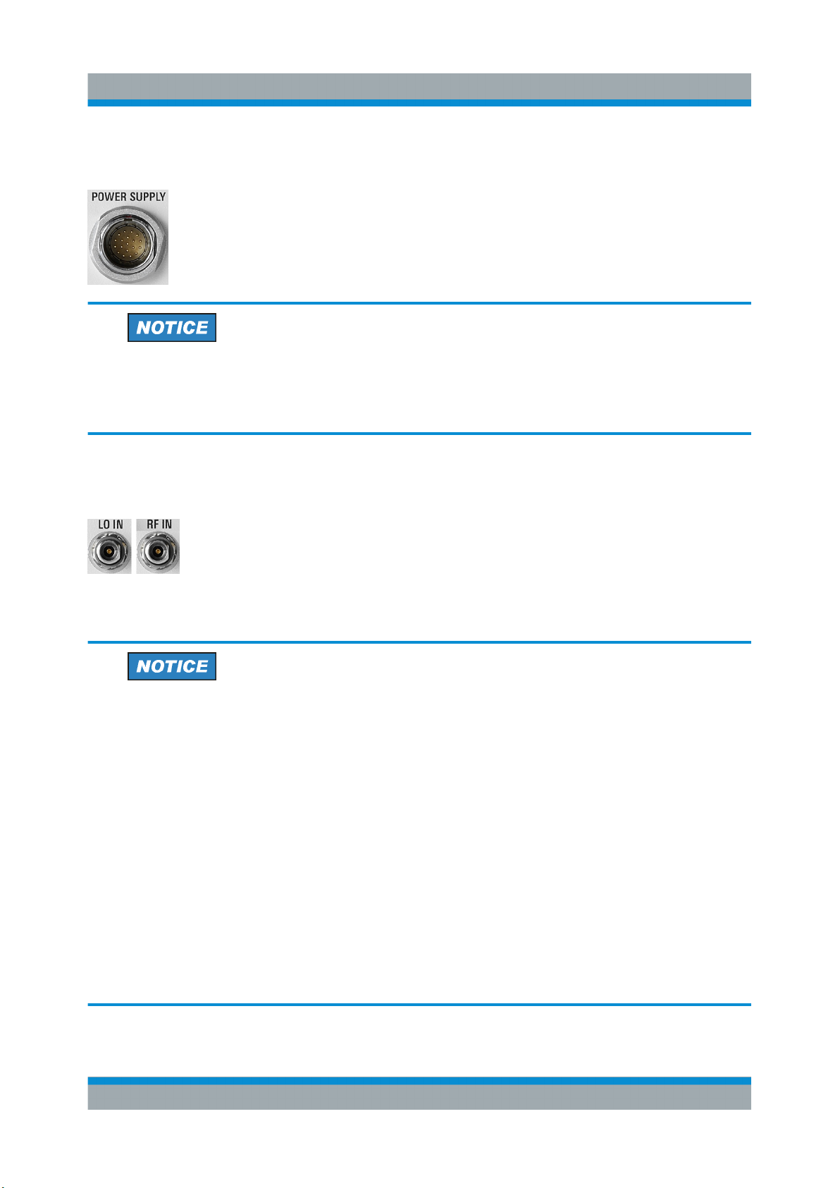
2.3.1 Power Supply Connector
In order to supply the R&S ZCxxx with power, connect it to the
external DC power supply R&S ZCPS. Always switch the power
supply off before removing the DC cable. For details, see the User
Manual of the R&S ZCPS.
Risk of instrument damage
The ZCPS has been designed for use with converters of the R&S ZCxxx
family. Do not use other power supplies.
2.3.2 RF Connectors – Input
Two 2.92 mm female input connectors: LO IN (local oscillator sig-
nal input) and RF IN (RF source signal input).
For correct cabling please refer to chapter 2.4.8, "Connecting the
RF Cables", on page 15.
Risk of instrument damage
The RF input power at the connectors RF IN and LO IN must not exceed
the maximum values quoted in the data sheet. These maximum values are
below the maximum RF source power of the network analyzer. The fre-
quency converter mode for your R&S ZCxxx ensures compatible source
powers. Therefore, activate this mode before you connect RF IN and LO IN
to the NWA.
Connect the R&S ZCxxx to the power supply R&S ZCPS. Then establish a
USB connection between NWA and R&S ZCxxx. When prompted "Config-
ure Two-Port Measurement Setup…?", select "Yes". Now the RF and LO
cables can be connected safely. This procedure is not required if the fre-
quency converter mode suitable for your R&S ZCxxx is already active, e.g.
when you have just switched the NWA off and on.
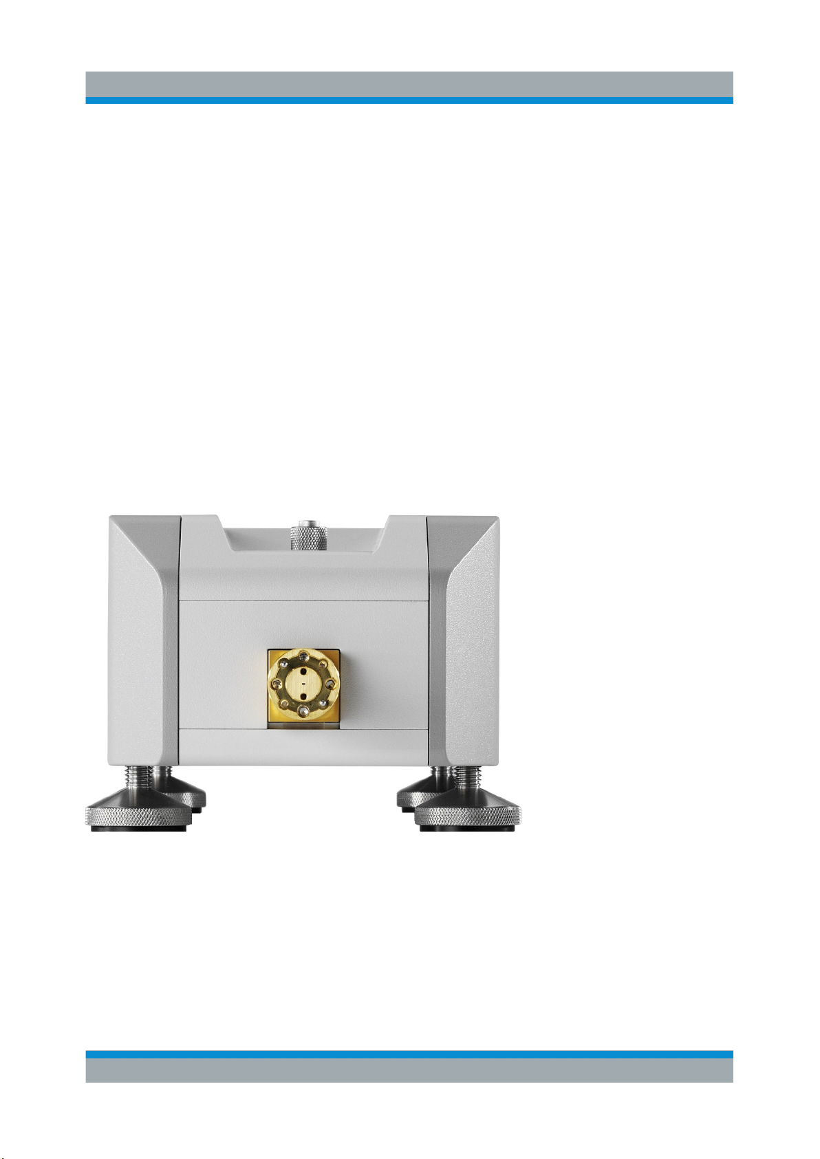
Rear Panel

Preparing for Use
R&S® ZCxxx
11Getting Started 1177.5156.02 ─ 03
2.3.3 RF Connectors – Output
Two SMA female output connectors: MEAS OUT (measurement
signal output) and REF OUT (reference signal output).
For correct cabling please refer to chapter 2.4.8, "Connecting the
RF Cables", on page 15.
2.3.4 USB Connector
The USB Type B connector is used to connect the R&S ZCxxx to
the NWA (R&S ZVA/ZVT) via USB.
2.4 Putting the Converter into Operation
This section describes the basic steps to be taken when setting up the frequency
converter for the first time.
Risk of instrument damage
Before turning on the converter, please make sure that the following condi-
tions are fulfilled:
●Converter covers are in place and all fasteners are tightened.
●Ventilation openings are unobstructed.
●The converter is dry and does not show condensation.
Non-observance may cause damage to the converter!
2.4.1 Unpacking the Converter and Checking the Shipment
When you receive the converter, please take the following steps:
1. Unpack the converter and the other contents from the cardboard shipping box.
2. The shipment must include the following items:
Putting the Converter into Operation

Preparing for Use
R&S® ZCxxx
12Getting Started 1177.5156.02 ─ 03
● converter
● DC supply cable
● USB cable
● IF cable EXT REF
● IF cable EXT MEAS
● plastic case with 8 flange screws 4-40 UNC 7.6 and 4 flange screws 4-40
UNC 9.24
● plastic case with 8 precision dowels 1.566 mm ± 0.001 mm
● 3/32” hex ball driver
● Getting Started (this document)
3. Inspect the frequency converter, especially the test port adapter and the test
port flange surface, to make sure that it has not been damaged during ship-
ment. Should the converter be damaged, immediately notify the shipping com-
pany and keep the packing material.
Risk of damaging waveguide flanges
The waveguide flanges of the converter and of the test port adapters must
be protected against scratches and other mechanical damages. Further-
more the waveguides must be shielded from dust.
Protect the waveguide flange of the converter by leaving the test port
adapter mounted. When the converter is not in use, slip a protective cap
onto the adapter.
2.4.2 Setting up the Converter
The frequency converter is designed for use under laboratory conditions on a flat
bench top or mounted on a wafer probe station. Four M8 threads are provided on
all long sides of the converter in order to allow for mounting the converter on a flat
surface. Some on-wafer measurement applications may also require the con-
verter to be tilted in order to bring the test port closer to the chuck. In these cases,
an additional bent waveguide adapter may be needed in front of the test port
adapter in order to compensate for the tilt angle.
The general ambient conditions required at the operating site are as follows:
●The ambient temperature must be in the ranges specified for operation and for
compliance with specifications (see data sheet).
Putting the Converter into Operation

Preparing for Use
R&S® ZCxxx
13Getting Started 1177.5156.02 ─ 03
●All ventilation openings must be unobstructed.
Risk of instrument and DUT damage
To avoid damage of electronic components of the DUT and the frequency
converter, the operating site must be protected against electrostatic dis-
charge (ESD).
To prevent ESD damage use the wrist strap and grounding cord supplied
with the network analyzer and connect yourself to the GND connector at the
front panel of the NWA.
2.4.3 Adjusting the Feet of the Converter
The instrument can be used with four feet attached to the respective bottom side
(depending on the orientation). When the DUT is mounted between two convert-
ers (see chapter 2.4.10, "Mounting a DUT", on page 18) use the feet for align-
ment of the complete setup. A bubble level may help to align each converter hori-
zontally prior to fitting the DUT.
2.4.4 Connecting the Converter to the DC Supply
Switch the converter power supply R&S ZCPS off. Connect the R&S ZCxxx to
either output CONVERTER 1 or CONVERTER 2 of the R&S ZCPS, using the
enclosed DC supply cable.
2.4.5 Connecting the Converter to the NWA via USB
Connect the R&S ZCxxx to the NWA using the enclosed USB cable.
A R&S ZCxxx must be connected to a R&S ZVA/ZVT at least once in order to
transfer the characteristic data of the converter to the NWA. After that, the con-
verter remains known to the NWA and can be selected (by type and serial num-
ber) in the "Frequency Converter" tab of the analyzer firmware's "System Config-
uration" dialog.
Putting the Converter into Operation

Preparing for Use
R&S® ZCxxx
14Getting Started 1177.5156.02 ─ 03
Firmware and Operating System Requirements
Support of the R&S ZCxxx converters requires firmware version 3.40 or
higher to be installed on the NWA. If the operating system of the NWA is
Windows® XP, make sure that it has been upgraded at least up to service
pack 2. Otherwise USB communication between NWA and converter will
fail. In case an upgrade of the operating system is needed, please contact
your local Rohde & Schwarz service.
2.4.6 Switching the Converter On
Switch the R&S ZCPS on. After a short time, both the LED of the power output to
which the converter is connected and the LED on the rear panel of the converter
should light up green. If the LED on the R&S ZCPS lights up red, at least one
supply voltage is missing. Contact R&S service in this case.
If the NWA is not yet in the frequency converter mode for the respective
R&S ZCxxx, a "Configure Two-Port Measurement Setup…?" dialog appears. Pro-
ceed by selecting "Yes".
2.4.7 LED Signaling
The following table lists all possible states of the converter LED along with their
associated fault states:
Color Fault State
green No fault
yellow At least one fan is not working properly (rota-
tional speed is out of range or fan stands still)
orange Temperature is out of range. If it exceeds a
critical level, the power supply is switched off
red At least one supply voltage is out of range or
missing
In case of an error, a warning message indicating the current error (fan, voltage
or temperature) is displayed on the NWA. Both warning message and converter
LED remain in the respective state as long as the fault condition persists. If more
Putting the Converter into Operation

Preparing for Use
R&S® ZCxxx
15Getting Started 1177.5156.02 ─ 03
than one fault condition is fulfilled, both warning message and LED show the
most severe one.
2.4.8 Connecting the RF Cables
The connectors RF IN, LO IN, MEAS OUT and REF OUT have to be connected
to the NWA; LO IN can alternatively be connected to an external generator.
Switch off the converter power supply R&S ZCPS before connecting the RF
cables.
Risk of connector and cable damage
Tightening the cables too strongly may damage cables and connectors.
Loose tightening may result in inaccurate measurement results.
Therefore always use an appropriate torque wrench, suitable for the type of
connector. Rohde & Schwarz offers an optional 5/16” torque wrench that fits
for SMA, 3.5 mm, 2.92 mm and 1.85 mm connectors (order number
1328.8534.35). Similar wrenches are available for other sizes of spanner,
too. See ordering information in R&S ZCxxx data sheet or product bro-
chure.
Connecting the input connectors (RF IN, LO IN)
The type of cable required for connecting the input connectors depends on the
type of the network analyzer / external generator. Since the converter inputs are
fitted with 2.92 mm female connectors, the cable should ideally have male con-
nectors of the same type (e.g. R&S ZV-Z195, order number 1306.4536.xx). Alter-
natively, 3.5 mm or SMA male connectors are possible. These are mechanically
compatible with 2.92 mm connectors while providing tolerable electrical mismatch
(e.g. R&S ZV-Z193, order number 1306.4520.xx).
For a complete test setup for a 2-port transmission measurement - as shown in
figure 2-4 - a cable length of about 1 m is recommended. For a setup with only
one converter shorter cables may be sufficient. Always use cables with low
attenuation and excellent phase stability.
Depending on the NWA model, additional 1.85 mm to 2.92 mm adapters may be
required to connect the cables.
Putting the Converter into Operation

Preparing for Use
R&S® ZCxxx
16Getting Started 1177.5156.02 ─ 03
1. Connect port 1 or port 2 of the analyzer to RF IN of the converter.
2. Connect port 3 or port 4 of the analyzer to LO IN of the converter.
For NWAs with 4 sources (R&S ZVA24 var. 28, R&S ZVA40 var. 48 or
R&S ZVA67), connect LO IN to port 4 only. For these NWA models, or in
case an external generator is used, a power splitter is required for a two-port
converter setup. If the outputs of the splitter are so close that two cables can-
not be mounted in parallel, additional angled adapters are required. This setup
is shown in figure 2-5 below.
If a power splitter is used and the phases of S21 and S12 deviate or drift by
equal magnitude, but opposite sign, check the phase stability of the LO paths
of both converters.
The required adapters and splitters are offered as complementary adaption kits
(see "Adaption Kits R&S ZCAK" on page 17).
Fig. 2-4: Test setup for 2-port transmission measurement with R&S
ZC330 and a NWA
with two sources
Putting the Converter into Operation

Preparing for Use
R&S® ZCxxx
17Getting Started 1177.5156.02 ─ 03
Connecting the output connectors (MEAS OUT, REF OUT)
Suitable cables for connecting the output connectors to the network analyzer are
included in the converter shipment. The connectors of these cables are labeled
accordingly.
R&S ZVA50 and R&S ZVA67 require additional 1.85 mm to 2.92 mm adapters to
connect the cables. These adapters are offered as complementary adaption kits
(see "Adaption Kits R&S ZCAK" on page 17).
1. Connect MEAS OUT of the converter to the NWA. Use the MEAS IN connec-
tor of the NWA port that provides the RF source signal.
2. Connect REF OUT of the converter to the REF IN connector of the same
NWA port.
Fig. 2-5: Test setup for 2-port transmission measurement with R&S ZC330 and a NWA
with four sources
Adaption Kits R&S ZCAK
As explained in the previous sections, depending on the NWA model, additional
adapters, power splitters and angled adapters may be required to connect the
Putting the Converter into Operation

Preparing for Use
R&S® ZCxxx
18Getting Started 1177.5156.02 ─ 03
cables. Rohde & Schwarz offers three different adaption kits R&S ZCAK to meet
the requirements of different NWAs:
●For the R&S ZVA24 var. 28 and the R&S ZVA40 var. 48 (NWAs with four
sources), Rohde & Schwarz offers the adaption kit R&S ZCAK Var. 24 (order
number 1323.7746.24).
It includes a power splitter and two right angled SMA (m-m) adapters.
●For the R&S ZVA50, Rohde & Schwarz offers the adaption kit R&S ZCAK Var.
50 (order number 1323.7746.50).
It includes four 1.85 mm (f) to 2.92 mm (m) adapters and four 1.85 mm (m) to
2.92 mm (f) adapters.
●For the R&S ZVA67, Rohde & Schwarz offers the adaption kit R&S ZCAK Var.
67 (order number 1323.7746.67).
It includes a power splitter and two right angled SMA (m-m) adapters, three
1.85 mm (f) to 2.92 mm (m) adapters and four 1.85 mm (m) to 2.92 mm (f)
adapters.
2.4.9 Switching the Converter On
Switch the R&S ZCPS on. After a short time, both the LED of the power out to
which the converter is connected and the LED on the rear panel of the converter
should light up green. For the meaning of the LED color refer to chapter 2.4.7,
"LED Signaling", on page 14.
After switching the measurement setup on, a warm-up time of one hour is
required to ensure accurate measurements.
2.4.10 Mounting a DUT
The DUT has to be mounted to the test port adapter at the front of the converter.
Use the included screws and hex ball driver. For higher precision, a torque-con-
trolled hex ball driver R&S ZV-Z1000 is available as an accessory (order number
1314.5467.02). Rohde & Schwarz also offers a special angled hex ball driver
R&S ZCAW (order number 1175.1960.00) that can advantageously be applied in
the tight space between rear side of the test port adapter flange and converter
front side (see figure 2-6).
Putting the Converter into Operation

Preparing for Use
R&S® ZCxxx
19Getting Started 1177.5156.02 ─ 03
Fig. 2-6: Angled hex ball driver R&S
ZCAW (accessory)
For precision calibrations and measurements, use the inner dowels at the test
port adapter. A tight and accurate connection is very important to ensure precise
measurement results.
For a two- or n-port measurement setup converters and DUT have to be aligned
accurately, using the adjustable instrument feet. A bubble level may help for
proper alignment.
2.5 Maintenance
The frequency converter does not require any special maintenance. Make sure
that the air vents are not obstructed. The outside of the instrument is suitably
cleaned using a soft, lint-free dust cloth.
Risk of instrument damage
Cleaning agents contain substances that may damage the instrument. Sol-
vent containing cleaning agents may e.g. damage varnish or labeling.
Never use cleaning agents such as solvents (thinners, acetone etc.), acids,
bases or other substances.
Maintenance

Preparing for Use
R&S® ZCxxx
20Getting Started 1177.5156.02 ─ 03
For Rohde & Schwarz support center address and a list of useful R&S contact
addresses refer to the pages at the beginning of this document.
2.6 Storage and Transport
For storage and transport, use either the original packaging or the transport case
R&S ZCSTC, order number 1323.7730.00 (see figure 2-7).
The case is designed to house two converters R&S ZCxxx and a power supply
R&S ZCPS along with the accessories delivered with them. Furthermore it offers
space for a waveguide calibration kit R&S ZV-WRxx, (torque) wrenches and other
accessories. A dedicated cable pocket is also provided.
Fig. 2-7: R&S ZCSTC Converter Set Transport Case for two R&S
ZCPS
Before placing the converter in the case, slip the protective caps onto the wave-
guide test port and the coaxial connectors on the rear panel.
The converter can be stored at the temperature range quoted in the data sheet.
Storage and Transport
Other manuals for ZC Series
1
Table of contents
Other R&S Media Converter manuals