Rane C4 User manual

Manual-1
C4
QUAD COMPRESSOR / LIMITER
Quick Start
Rejected Rane advertising slogan #1743: “C4. It’ll blow your mind!”
We’re not entirely sure why the marketing department didn’t like the idea, but be assured: unlike its explosive material namesake,
the C4 Quad Compressor will not blow up. Heck, it won’t even spark or sizzle under normal circumstances. e only thing smokin’
will be your mix, thanks to the C4’s smooth compression, precise de-essing and ultra-fast limiting.
Each of the C4’s four channels offers a full-featured compressor with selectable COMPressor and DE-ESSer modes. In addi-
tion, an oversampled, brick wall LIMITER is included for catching signal peaks. COMP, THRESHOLD, RATIO, ATTACK,
RELEASE and KNEE give full control over the audio envelope. e compressor is toggled on and off using the ACTIVE/BYPASS
switch; the Limiter is engaged at all times and is not affected by this switch. Limiter operation is completely independent of the com-
pressor with its own LIMIT THRESHOLD control and Headroom meter. Channels 1 & 2, and 3 & 4 can be LINKed to maintain
a proper left/right stereo image, with channels 1 and 3 acting as the MASTERs, respectively.
For the ultimate in dynamics processing flexibility, the C4 includes both internal and external side-chain functions, with a full
PEQ (parametric EQ) section included for good measure. External side-chain mode is automatically selected whenever a connector is
plugged into the rear panel SIDE-CHAIN jack. Selecting LISTEN mode routes the side-chain audio to the channel output, allow-
ing you to hear the effect of PEQ adjustments when doing frequency-sensitive compression or de-essing. If you'd prefer to not use the
side-chain PEQ, simply set the PEQ GAIN to 0 dB.
Setting up the C4 is a breeze thanks to the fast, accurate side-chain and Gain Reduction combination meter. For users unfamiliar
with de-essing, the ▼ pointer on each control indicates a recommended setting for this specialized application. e Auto attack and
release mode speeds up sound check, and the Tips and Tricks on page Manual-8 serve as a handy reference guide for getting started
with compression. ank you for taking the time to read this Quick Start. We now return you to your regularly scheduled sound
check or recording session.
OPERATORS MANUAL
0
0
6
3
12
24
dB QUAD
COMPRESSOR
-20
-10
0
-40
-30
+20
+10
-20
-10
0
-40
-30
+22
+10
msms dBu
dBu
dBHzoct
Headroom
dB
8-3 -1 12 4 2-6-12 1
n:1
MASTER SLAVE
10
2
1.5 5 -6 +6 -6 +6 -6 +6 -6 +6
1
500
100
50 250
25
10
2
1 5
0.5 20k
640
125
3.15k
20
500
125 1 s
2 s50
25
+12-12
+12-12
0
0
6
3
12
24
dB
-20
-10
0
-40
-30
+20
+10
-20
-10
0
-40
-30
+22
+10
msms dBu
dBu
dBHzoct
Headroom
dB
8-3 -1 12 4 2-6-12 1
n:1
10
2
1.5 5
1
500
100
50 250
25
10
2
1 5
0.5 20k
640
125
3.15k
20
500
125 1 s
2 s50
25
+12-12
+12-12
0
0
6
3
12
24
dB
-20
-10
0
-40
-30
+20
+10
-20
-10
0
-40
-30
+22
+10
msms dBu
dBu
dBHzoct
Headroom
dB
8-3 -1 12 4 2-6-12 1
n:1
MASTER SLAVE
10
2
1.5 5
1
500
100
50 250
25
10
2
1 5
0.5 20k
640
125
3.15k
20
500
125 1 s
2 s50
25
+12-12
+12-12
0
0
6
3
12
24
dB
-20
-10
0
-40
-30
+20
+10
-20 -10 0
-40
-30
+22
+10
msms dBu
dBu
dBHz
oct
Headroom
dB
8-3 -1 12 4 2-6-12 1
n:1
10
2
1.5 5
1
500
100
50 250
25
10
2
1 5
0.5 20k
640
125
3.15k
20
500
125 1 s
2 s50
25
+12-12
+12-12
18 18 18 18
C4
SIDE-CHAIN
RELEASEATTACK KNEE
GAIN
FREQUENCYBANDWIDTH
LIMIT THRESHOLD
RATIO GAIN
COMP THRESHOLD
1 2
LINK
Auto
Auto
Soft
Hard
dBr Reduction dB
Listen De-essComp
LIMIT
BYPASS
ACTIVE
PEQ
SIDE-CHAIN
RELEASEATTACK KNEE
GAIN
FREQUENCYBANDWIDTH
LIMIT THRESHOLD
RATIO GAIN
COMP THRESHOLD
Auto
Auto
SoftHard
dBr Reduction dB
Listen De-essComp
LIMIT
BYPASS
ACTIVE
SIDE-CHAIN
RELEASEATTACK KNEE
GAIN
FREQUENCYBANDWIDTH
LIMIT THRESHOLD
RATIO GAIN
COMP THRESHOLD
3 4
LINK
Auto
Auto
SoftHard
dBr Reduction dB
Listen De-essComp
LIMIT
BYPASS
ACTIVE
SIDE-CHAIN
RELEASEATTACK KNEE
GAINFREQUENCYBANDWIDTH
LIMIT THRESHOLD
RATIO GAIN
COMP THRESHOLD
Auto
Auto
SoftHard
dBr Reduction dB
Listen De-essComp
LIMIT
BYPASS
ACTIVE
PEQ PEQ PEQ
POWER
TH TH TH TH
WEAR PARTS: This product contains no wear parts.
Contents
Quick Start ....................................................................1
Dynamics 101 Revisited ............................................2
Compression .....................................................................2
De-essing ...........................................................................2
Peak Limiting .....................................................................3
Making Connections ..................................................4
Front Panel Controls .................................................4
Side-chain and Gain Reduction Meters .....................4
MASTER / SLAVE Stereo Link .....................................5
ACTIVE / BYPASS ..........................................................5
COMPressor THRESHOLD, RATIO and GAIN ......6
ATTACK, RELEASE and KNEE ....................................6
SIDE-CHAIN Mode and Listen ....................................7
SIDE-CHAIN Parametric EQ ........................................7
Limit Threshold and Headroom Meter ........................8
Tips and Tricks .............................................................8
Complete specifications and the internal block diagram are
found in the C4 Data Sheet, included in this booklet.

Manual-2
Dynamics 101 Revisited
Introduction
Compressors and limiters are in the business of automati-
cally controlling the volume or dynamics of sound, just like your
hand on the fader, or the fat man dancing in front of the mid-
range cabinet. Used wisely, often in conjunction with each other
or with equalization or filtering, dynamics processors improve
the intelligibility of voice and the subjective effect of music.
However, in the wrong hands they can sound terrible.
Heavy compression (low threshold and a high ratio) often
sounds nasty. e timbre of the sound changes, becoming hard
and closed and not nearly as sweet and open as the sounds
you envisioned when you got into this business. On the other
hand, attack times optimized for pleasant compression may
not track initial transients quick enough. In addition, pump-
ing and breathing may accompany heavy compression, i.e., the
background noise rises way out of proportion to the foreground
sound as the compressor releases. Result: it just does not sound
good.
erefore, no matter how you slice it, compressors and limit-
ers are just fancy electronic volume controls. ink of them as an
extra hand on a control, turning the volume down and turning
it back up again. Luckily, this electronic hand is quick and ac-
curate, but it is just adjusting a volume control.
Compression
A compressor, when the input signal reaches the level set
by the threshold control, begins turning down the signal by an
amount set by the ratio control. Modern compressors make the
loud signals quieter, but do not make the quiet parts louder.
(However, by keeping the loud signals under control, you can
turn up the output level, which will make the quiet parts louder
along with the rest of the signal.)
Primary uses are 1) reduce dynamic range of vocalists and
other musical instruments that exceed the recording or repro-
duction capability; 2) prevent clipping and distortion in live
sound systems or recording chains; 3) smooth and balance an
instrument such as a bass guitar with wide dynamic range and
string-to-string level variations; 4) reduce vocal sibilance (de-
esser); 5) produce louder recordings for broadcast; and 6) even-
out paging variations due to different speakers in large systems.
Signal Path
A compressor has two internal paths: the signal and the side-
chain. e signal path is the route the main signal takes through
the unit: from the input circuits to the gain control section and
exits through the output circuits. e signal chain goes through
the “volume control” in the “hand on a control” analogy.
Side-chain
e side-chain is the hand that controls the volume. Side-
chain circuitry, also known as the detector, examines the input
signal and issues a control message to adjust the gain of the main
signal path.
Full-featured compressors, like the C4, offer both internal
and external side-chain options. When the internal option is
selected the compressor’s input signal feeds the detector. is
arrangement works well for most applications, and is especially
effective with the C4 due to the parametric EQ built into the
side-chain. e external side-chain allows any signal source, con-
nected to a dedicated input jack, to feed the detector, thereby de-
termining the compressor’s response. is external signal may be
a specially filtered version of the input signal, using an outboard
EQ for example, or it may be another signal altogether.
It is important that the side-chain signal is not heard. For
instance, if you added treble boost to the side-chain audio (either
by using the C4’s built-in PEQ or an outboard EQ), it would not
affect the high frequencies in the main signal path, but it would
cause them to cross the threshold sooner and more often. Large
peaks of treble would cause heavy compression with no compres-
sion at other times. is example is the basic de-esser, a circuit to
remove excess sibilance. (ere is a much more sophisticated and
effective de-esser built-into the C4, but more on that later.) With
a bass boost, you can make a de-thumper, and with a midrange
boost a de-nasaler.
ere are a number of parameters governing side-chain activ-
ity, but the four primary ones are reshold, Ratio, Attack time
and Release time.
De-essing
Contrary to popular belief, proper de-essing is not as simple
as placing a bandpass or high-shelf filter in the side-chain and
calling it done. True de-essing involves comparing the relative
difference between the troublesome sibilants (“sss” sounds) and
the overall broadband signal, then setting a threshold based on
this difference. Lucky for you, the C4’s De-ess mode uses such
an arrangement.
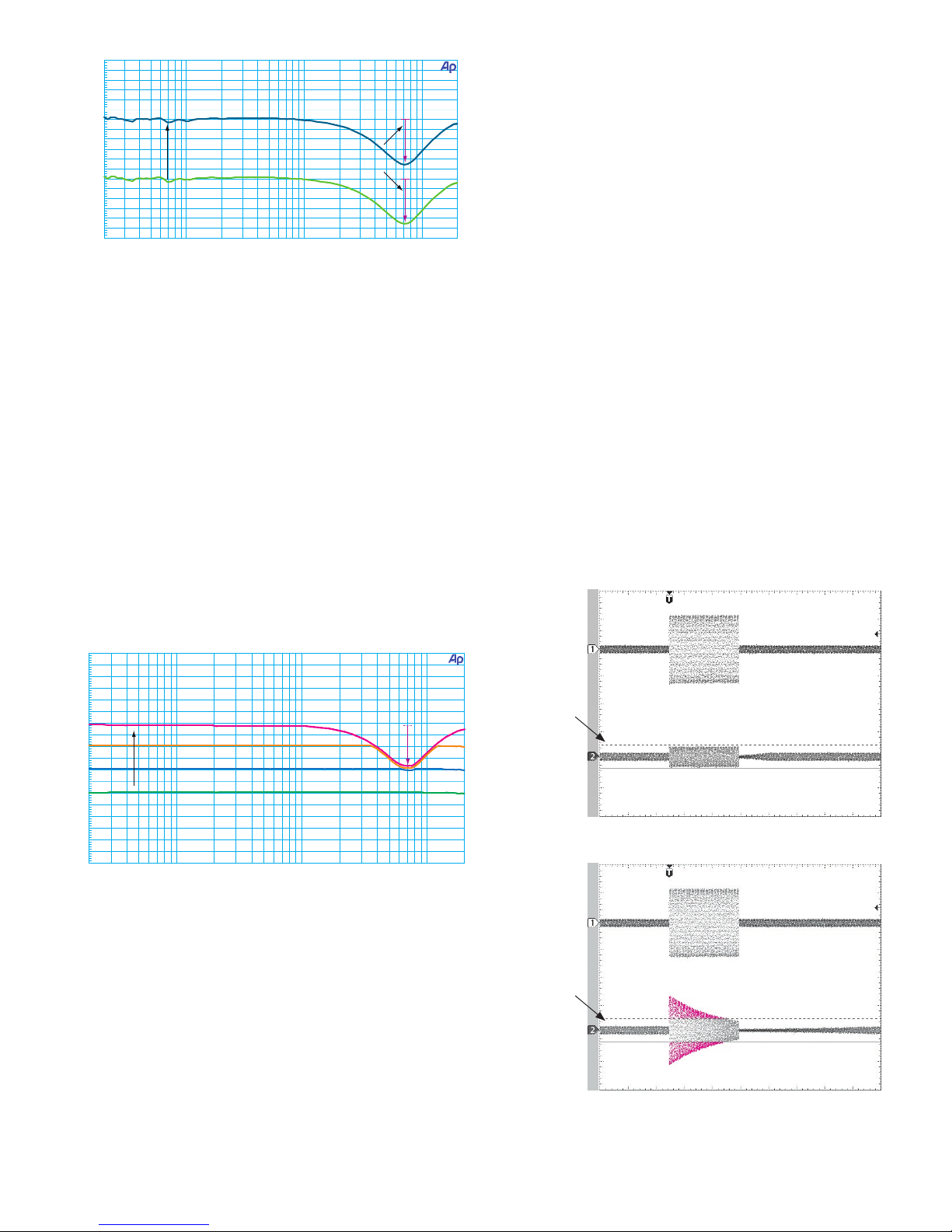
When the C4 is set to De-ess, the average level of the
broadband signal (20 Hz to 20 kHz) is compared to the average
level of a bandpass filter as defined by the PEQ frequency and
bandwidth controls. e reshold setting defines the rela-
tive threshold, or difference, between broadband and bandpass
levels that results in compression of sibilants. Because de-essing
depends on the ratio of sibilant to broadband signal levels, it is
not affected by the absolute signal level, allowing the De-esser
to maintain the correct ratio of broadband to sibilant material
regardless of signal level, as shown in Figure 2
�
�
�
�
�
�
�
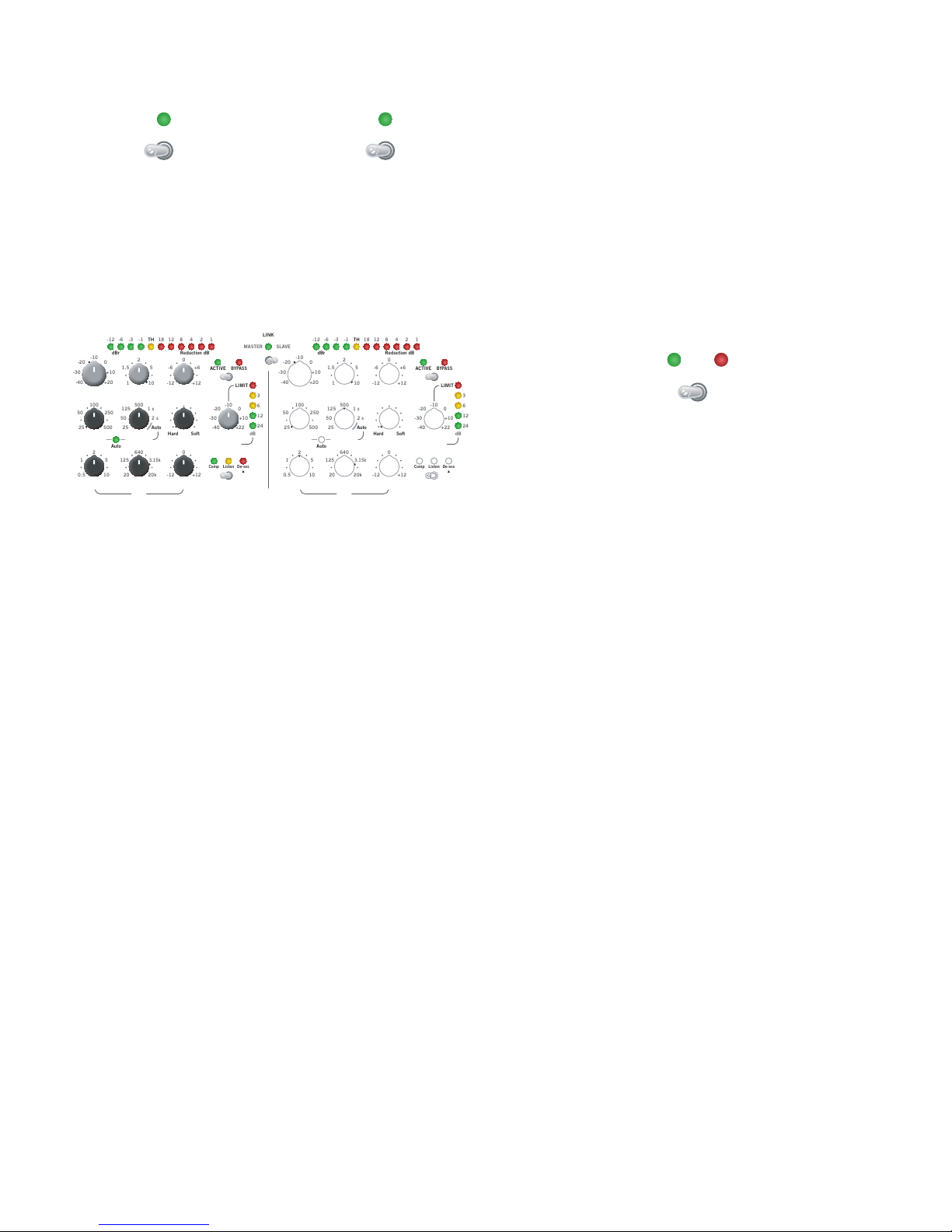
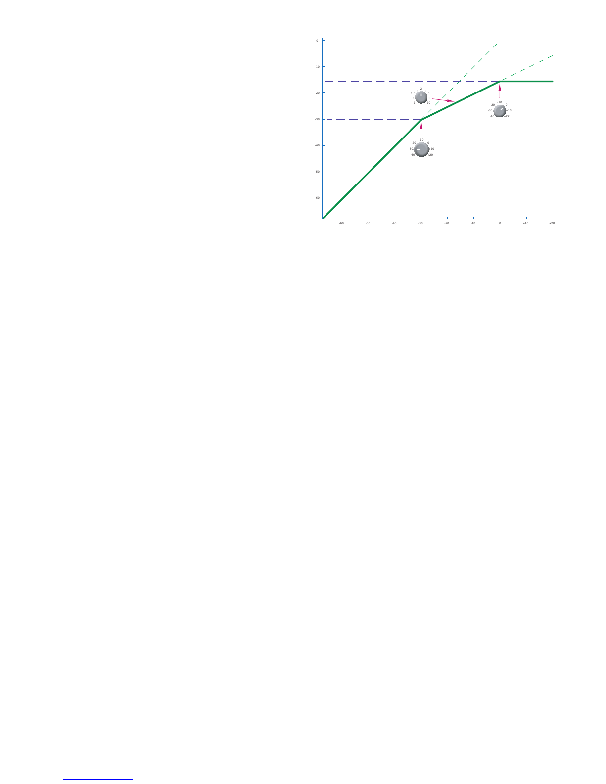
Figure 1. Compressor and Limiter functions

Manual-3
is is all nice and technical, and repeating it word for word
will undoubtedly impress friends and family, but what does it
really mean? Simple: de-essing performance is consistent and
predictable, regardless of how loud or quiet the singer/talker is.
Taming sibilance when the talker is quiet is just as important as
when the talker is at a fevered pitch. Only a true de-esser offers
this performance.
Figure 3 shows what happens when a compressor (not a true
de-esser) is used in conjunction with a side-chain EQ. Sibilance
during loud passages is attenuated, but there is little or no gain
reduction during quiet passages, even though there may still
be a significant amount of “sss” in a person’s voice. For a given
threshold this often results in an overly-aggressive effect during
the loud choruses, and a completely ineffective result during the
hissy, whispered verses. Solution: use the C4’s dedicated De-ess
mode instead.
Peak Limiting
A limiter is just a compressor with a really high ratio, right?
Well…not exactly. Although the two devices use similar termi-
nology (reshold, Attack, Release, and so on), they serve two
completely different purposes and therefore operate in different
manners. Fundamentally, a compressor uses an rms detector to
keep the average level of a signal under control, while a limiter
uses a peak detector to act on the instantaneous level of the
signal.
Primary uses of limiters: 1) preventing clipping and distor-
tion in power amplifiers, 2) protection of loudspeakers from
damage resulting from destructive transients [like the proverbial
dropped microphone] 3) preventing overs [clipping] during
digital recording 4) preventing overmodulation of the transmit-
ted signal in broadcast.
Figure 4 shows the effect of limiting a signal. e top line is
the original, full volume input signal we need to limit – perhaps
the unfortunate blast of noise when the vocalist inadvertently
unplugs the phantom-powered mic. e bottom line shows the
limited output. At no point does the output signal ever exceed
the threshold, demonstrating the limiter’s brick wall capability.
Contrast this with Figure 5, which shows a compressor set to a
high ratio (∞:1), and a fast attack time. Due to the compressor’s
averaging effect, the output easily overshoots the threshold, and
transient peaks are missed altogether. And it’s these peaks which
can potentially ruin your speakers or the perfect recording take,
and possibly your reputation.
Figure 2. The C4’s De-essing performance remains consistent with
varying input levels
Figure 3. A compressor with a simple side-chain EQ boost is not a true
de-esser. Gain reduction is directly affected by varying input levels,
not the actual ratio of broadband to sibilant material.
Figure 5 Compressor used as a limiter. Signal peaks can still exceed
threshold, even at high ratio settings.
Input
Output
Limit Threshold
Input
Output
Limit Threshold Overshoot
Figure 4 Limiter performance showing brick wall characteristic.

Manual-4
Making Connections
e C4 features auto balanced/unbalanced XLR and ¼"
TRS input and output jacks, permitting connection to virtually
any mixing console. Side-chain inputs are also auto balanced/
unbalanced, on ¼" TRS only. Dynamics processors typically
connect using a mixing console’s insert points (send/return),
although they can be used in-line, such as when compressing or
limiting an overall mix, for example.
Figure 6. Connection to a mixing console.
Figure 7. Using an external equalizer in the side-chain.
Front Panel Controls
Each channel of the C4 features the following meters and
controls:
Side-chain and Gain Reduction Meters
8-3 -1 12 4 2-6-12 118
dBr Reduction dB
TH
is triple-function meter displays the side-chain level,
threshold indication and amount of gain reduction being ap-
plied. It allows you to see at a glance exactly what the compressor
is doing at all times.
Side-chain Level Display
In Compressor mode, the floating meter displays the side-
chain level relative to the reshold (dBr), making it easy to gauge
how close the signal is to the onset of compression. e dBr
indicators light from left to right as the signal approaches the
threshold. At threshold, the yellow TH indicator is lit. Above
threshold the TH indicator remains lit and gain reduction oc-
curs. Side-chain meter ballistics follow the rms detector time
constant of 30 ms.
In De-ess mode, the side-chain meter displays the relative
difference between the broadband program material and the
bandpass signal defined by the PEQ, as compared to the set
reshold.
Example: With THRESHOLD set to -15 dB, the TH indica-
tor lights when the sibilant portion of the program material is 15
dB below the broadband program material. If the sibilants are
18 dB below the broadband material, then the –3 dBr indicator
is lit.
Gain Reduction Display
e Gain Reduction meter displays the amount of gain cor-
rection presently applied to the signal, lighting from right to left
as the amount of gain reduction increases. In Compressor mode,
this meter display the amount of gain correction being applied
to the broadband program material. In De-ess mode. this meter
shows the amount of gain correction being applied to the dy-
namic EQ (DEQ) in the main signal chain. is meter does not
reflect any gain reduction occurring due to limiting.
Gain Reduction meter ballistics follow the actual gain cor-
rection value as determined by the THRESHOLD, RATIO,
ATTACK, RELEASE and KNEE controls. Gain reduction may
be indicated when the reshold indicator is off, as attack and
decay rates may dictate continued gain reduction even when the
rms level is below threshold.

Manual-5
MASTER / SLAVE Stereo Link When channels are Linked
• Bypassing the Master channel does not automatically bypass
the Slave channel. Channel ACTIVE / BYPASS switches are
the only controls which do not follow the Master channel,
making it possible to bypass each channel individually.
• Selecting Listen on the Master channel automatically puts
both channels into Listen mode. Side-chain function switch
indicators are turned off on the Slave channel.
• Meters for Master and Slave channels remain active, indicat-
ing both channels are being processed.
ACTIVE / BYPASS
e MASTER / SLAVE switches link channels 1 & 2, or
channels 3 & 4 for stereo operation. When linked, the associ-
ated LINK indicator lights and only the controls of the Master
channel (channel 1 or channel 3) are active, with the exception
of channel ACTIVE / BYPASS switches. is feature helps pre-
serves a stable left/right image when compressing a stereo source,
such as a vocal or horn submix.
MASTER SLAVE
1 2
LINK
MASTER SLAVE
3 4
LINK
Figure 8. Active controls in Linked Mode
Stereo Linking in Compressor Mode
Linked Compressors use the rms sum of the two channels’
side-chains, and display this summed result on the side-chain
dBr meters of both channels. e Master channel settings deter-
mine the actual gain reduction characteristics.
Linked Controls in De-ess Mode
When channels are linked in De-ess mode, both channels
use the Master channels’ control settings, but the de-essing es-
sentially functions independently for each channel. Combining
the rms values of broadband and bandpass signals, as is done in
Compressor mode, is of no advantage in De-ess mode.
Stereo-Linked Limiters
When channels are linked, the Master channel Limit
reshold setting determines the maximum output level for
both channels. However, the greater of the two peak-detected
signals is used to control the gain of both Master and Slave
channels. For example, if the Slave channel signal exceeds the
Mater channel’s Limit reshold by 3 dB, both channels are
limited by 3 dB. e Limit Headroom meters remain indepen-
dent for both channels, as the dynamics of the Master and Slave
channels may be quite different.
�
�
�
�
�
�
�
�
�
�
�
�
�
�
�
�
�
�
�
�
�
�
�
�
�
�
�
�
�
�
�
�
Selecting BYPASS disables all Compressor/De-esser process-
ing, including the GAIN control. e side-chain dBr meter,
threshold indicator and gain reduction meter continue to operate
when a channel is bypassed. Similarly, the side-chain Listen
function is also available. Channels can be individually by-
passed, even in Linked mode.
Note: e Limiter is active at all times and is not affected
by the BYPASS switch. To bypass the Limiter, simply rotate the
Limiter reshold control fully clockwise (+22 dBu setting).
BYPASS
ACTIVE

Manual-6
COMPressor THRESHOLD, RATIO and GAIN
0
-20
-10
0
-40
-30
+20
+10
dBu dBn:1
10
2
1.5 5 -6 +6
1 +12-12
RATIO GAIN
COMP THRESHOLD
e threshold, like crossing through a doorway, is the begin-
ning point of gain adjustment. When the input signal is below
the threshold, a compressor acts like a straight wire. Above
threhsold, the side-chain asserts itself and turns the volume
down.
In Compressor mode, COMP THRESHOLD defines the
absolute level, adjustable from –40 dBu to +20 dBu, above which
compression begins. If soft-knee settings are used, the threshold
is defined as the point at the center of the knee. (See the KNEE
description for more details).
In De-ess mode, this control defines the relative difference
between the broadband program material and the bandpass
signal defined by the PEQ. e ▼ pointer between –10 dBu and
–20 dBu shows the typical setting for De-essing.
RATIO defines the ratio of Input change to Output change,
and is adjustable from 1:1 (straight wire, no change) to 10:1
(heavy compression), as shown in Figure 9. For example, a Ratio
of 4:1 means that a 4 dB change at the input causes only a 1 dB
change at the output.
e ▼ pointer at 10:1 shows the typical setting for De-
essing.
Figure 9. Input versus Output for various Ratio settings (hard knee)
Once you reduce the dynamic range using compression, you
can increase or decrease the overall loudness by adjusting the
GAIN. is control features a center-detent marking the unity
gain point, with a range of +12 dB or -12 dB on either side.
ATTACK, RELEASE and KNEE
ATTACK determines how fast the gain is turned down once
the signal exceeds reshold, and is adjustable from 25 ms (fast)
to 500 ms (slow). e ▼ pointer at 25 ms shows the typical set-
ting for De-essing.
RELEASE determines the rate of gain increase as less gain
reduction is required, and is adjustable from 25 ms (fast) to
2 seconds (slow). It is important to understand the difference
between release rate – as determined by this control – and release
time. e Release setting determines how long it takes for the
gain to change by 10 dB, not how long it takes to return to unity
gain (no gain reduction).
Example: with the Release control set to 1 s, when a signal
with 5 dB of gain reduction presently applied suddenly drops
below threshold, the release time is 0.5 s, calculated as follows:
Gain Reduction x Release = 5 dB x 1 s = 0.5 s
10 dB 10 dB
Auto Attack and Release
Unsure about how to set the Attack and Release controls?
Venue doors opening in 15 minutes and you need to speed
through sound check? No problem! Simply rotate the Release
control fully clockwise until Auto is lit, indicating the Attack
and Release settings are appropriately fixed for most types of
program material. e C4’s not entirely on auto pilot, though
– you still have full control over the reshold, Ratio, Gain, and
Knee settings.
We are the Knights of KNEE
KNEE controls the action of the compressor above and be-
low the threshold point. Hard knee does nothing until the signal
exceeds the threshold point, then applies full compression. Soft
knee begins applying a small amount of compression just before
the threshold point is reached, continues increasing compres-
sion through the threshold point and beyond, finally applying
full compression to the highest level signals. Depending on the
application and source material, soft knee settings can sound
more natural. On the other hand for maximum loudness before
compression (for equipment protection for instance), use hard
knee settings.
Knee span is adjustable from 0 dB (Hard) to 10 dB (Soft),
with the reshold always being at the center of this span. e
▼ pointer at the Hard Knee setting shows the typical setting for
De-essing.
msms
500
100
50 250
25
500
125 1 s
2 s50
25
RELEASEATTACK KNEE
Auto
Auto
SoftHard

Manual-7
Figure 10. The Hard Knee compression characteristic has a 0 dB span.
The Soft Knee compression characteristic has a 10 dB span.
SIDE-CHAIN Mode and Listen
SIDE-CHAIN Parametric EQ
Comp selects Compressor mode for the channel.
De-ess selects De-ess mode for the channel.
Tip: A small ▼ pointer next to a control indicates a typical set-
ting for De-essing.
Listen routes the side-chain signal to the channel output,
allowing you to hear exactly what the detector “hears,” and is
especially useful when making precise PEQ adjustments for fre-
quency sensitive compression or de-essing. e yellow indicator
flashes when Listen is engaged, as a friendly reminder to toggle
back to Comp or De-ess mode before show time.
e Listen source depends on the selected mode (Comp or
De-ess), so the switch operates as follows: when switching from
Comp to Listen, the Comp indicator remains lit and the Listen
indicator flashes, which signifies you are listening to the Com-
pressor side-chain PEQ response. When the switch is moved
to De-ess, the Listen and Comp indicators are turned off and
the De-ess indicator is lit. When the switch is then moved from
De-ess to Listen, the De-ess indicator remains lit and the Listen
indicator flashes, which signifies you are listening to the De-esser
bandpass filter response.
Remember: once the show begins the audience never hears
the filtered side-chain signal – unless you accidentally leave
Listen mode engaged, of course. If something sounds a bit odd
during the gig, look over at the C4 and see if any of the yellow
Listen lights are flashing. If so, casually saunter over to the rack
and toggle the side-chain out of Listen mode…as if you meant
to have it engaged for the first six songs.
SIDE-CHAIN
Listen De-essComp
e Side-chain PEQ filter operates in one of two ways,
depending on whether the channel is operating in Compressor
mode or De-ess mode.
PEQ in Compressor Mode
In Compressor mode, the PEQ section operates as a normal,
2nd-order, parametric filter with independent BANDWIDTH,
FREQUENCY and GAIN controls. e GAIN control has a
center detent position indicating 0 dB, or unity gain. Use the
PEQ to adjust the sensitivity of the rms detector to specific
frequencies. Boosting a particular frequency makes the detector
more sensitive to this frequency, while cutting makes it less sensi-
tive. Broadband compression still takes place; the filter does not
directly affect the frequency response of the main signal, as is
done with the dynamic EQ used in De-essing.
Example: reducing detector sensitivity to low frequencies
helps avoid the pumping and breathing often associated with
compressing an overall mix of instruments. Start by engaging
Listen mode and set the PEQ Gain to –12 dB with a bandwidth
of 1 to 2 octaves. Adjust the frequency and bandwidth controls
until most of the low frequency sound disappears (125 Hz is a
good start). Oh…and don’t forget to dis-engage Listen mode
when you’re done.
PEQ in De-ess Mode
In De-ess mode, the PEQ controls define a bandpass filter in
the side-chain and a dynamic EQ in the main signal path. e
difference in the rms level of the broadband signal and that of
the bandpassed side-chain signal is compared to the threshold,
and the dynamic EQ’s gain is automatically adjusted to maintain
the proper ratio of sibilant to non-sibilant content.
Example: while in De-ess mode with the Side-chain Listen
engaged, set the BANDWIDTH between 1 and 2 octaves, then
sweep the FREQUENCY control until only sibilant content is
heard (typically 3 to 6 kHz, but this frequency will vary slight
with different talkers). Lastly, adjust the COMP THRESHOLD
to achieve the desired amount of gain reduction during sibilant
passages. e PEQ GAIN control has no function in De-ess
mode.
Although it’s called De-ess mode, there’s nothing to stop you
from dialing in any offending frequency – like the annoying,
low-mid boost caused by a microphone’s proximity effect, or
that paint-peeling high C the singer always hits during the key
change, for example – and using the C4 to improve the sound.
0
dBHzoct
10
2
1 5
0.5 20k
640
125
3.15k
20 +12-12
GAIN
FREQUENCYBANDWIDTH
PEQ

Manual-8
LIMIT THRESHOLD and Headroom Meter
In addition to the Compressor / De-esser, each channel of
the C4 features an independent, brick-wall Limiter with an
instantaneous attack time, fixed 25 ms hold time and a fixed 6
dB/second release rate. e C4’s limiter uses oversampling in
order to ensure high frequency transients are properly detected
and acted upon.
e Headroom meter displays the difference, in dB, between
the LIMIT THRESHOLD and the present signal level. For
example, with LIMIT THRESHOLD set to +10 dBu, a peak
signal level of +4 dBu results in a display of 6 dB of remain-
ing headroom (+10 dB minus +4 dB equals 6 dB). e LIMIT
indicator lights when the present signal exceeds the set Limit
reshold. When setting the Limiter reshold keep in mind
that music often has peaks which are 12 to 20 dB higher than
the average (rms) value, which is displayed on the side-chain
meter.
Note: e Limiter is active at all times and is not affected by
the bypass switch. To bypass the limiter, simply rotate the Lim-
iter reshold control fully clockwise (+22 dBu setting).
6
3
12
24
dB
-20 -10 0
-40
-30
+22
+10
dBu
Headroom
LIMIT THRESHOLD
LIMIT
Initial Settings
Sometimes it is necessary to start from scratch. e draw-
ing above shows where to set the controls for no processing (the
black knobs have no affect at this point). en you can adjust
each section one at a time.
Suggested Settings
ere is no magic recipe of compressor settings which work
for every audio source in every performance situation. ere are,
however, a few key ingredients you can add to the ol’ dynam-
ics stew to get things going. Start with the suggested settings in
Table 1, then season to taste by adjusting the reshold until
your ears tell you it’s just right.
Vocals
A tough issue with vocals is the extreme dynamic range of
some singers. ose who can lull you to sleep and then scare
you with an unexpected blast. e difference between the soft
crooning and the loud climax represents too much signal change
for many preamps and mixers, causing them to clip and distort
badly. Compression and limiting comes to the rescue.
Use the limiter to prevent the extreme levels from causing
clipping and distorting the sound. With its automatic fast attack
and quick release mode, all you need to set is the Limit resh-
old. Set it as high as the next piece of equipment in the signal
path allows. e C4 gives you a wide setting range of -40 to +22
dBu that covers all requirements.
Compression is one of the most effective tricks for bring-
ing the vocals up in any mix, live or recorded. is is due to
the increase in perceived loudness which results from reducing
peaks and increasing the average level. Good settings for natural
sounding, yet compressed vocals, are a medium fast (25 – 50
ms) attack and a medium-slow (100 ms – 1 sec) release. Releas-
ing too quickly sounds unnatural, while attacking too slowly
misses the problem surges. Soft knee compression generally best
matches vocal dynamics. Adjust the ratio to match the dynamics
of the singer, with 2:1 being a good starting point.
Tips and Tricks
�
�
�
�
�
�
�
�
�
�
�
�

Manual-9
Bass
It is common for the sound mixer to reduce the bass signal
because it overwhelms the total system. Use a compressor to
smooth a bass sound by lessening the variations between the
strings or strongly resonant notes, and increasing sustain.
Typical settings for a bass guitar are a ratio of 4:1, with a
fast attack of 25 ms and a slow release of around 500 ms. ese
settings should produce a strong, smooth bass line to start with,
but feel free to adjust further as necessary. A hard knee setting
is often preferred since all that is desired is to tame the excessive
peaks and leave everything else alone.
Where does a compressor belong in a bass player’s signal
chain? Well, that depends on how you want it to function. As a
compressor/limiter for the input signal, it goes after the bass (if
the bass has a line-level output) and before the preamp. If it were
to function as a limiter to protect the speakers in the bass rig, it
would go after the preamp and before the power amp. Another
method is to insert the unit in the effect loop of the preamp.
is allows the bass signal to be affected by the pre-amp first,
then the compressor/limiter, and then sent to the power amp.
is can be desirable with tube pre-amps.
Guitar
Here is a suggestion on how to achieve a lower volume with-
out sounding as if you are playing out of a transistor radio: set a
slow attack time with a medium to slow release and a relatively
low threshold. Experiment from these initial settings.
One of the favorite uses of compression by guitarists is to in-
crease the sustain, or duration of a note after it is played. Carlos
Santana and Gabor Szabo are two musicians who use sustain to
great acclaim, although they did it the old-fashioned way of cre-
ating feedback by aiming the guitar pick-ups at the loudspeaker
and then jamming over it. A compressor creates a similar effect.
Set a high ratio and low threshold for long sustain, along with
fast attack and slow release. Again, experimentation produces
the best results.
ATTACK RELEASE RATIO KNEE
Vocals Medium to Fast Medium to Slow 2:1 to 4:1 Soft
Clicky Bass Fast Fast 4:1 or higher Hard
Mushy Bass Medium to Slow Medium to Slow 4:1 Hard
Raging Electric
Guitar
Fast Slow 4:1 or higher
(more sustain)
Hard
Acoustic Guitar Medium to Slow Medium to Slow 4:1 Medium
Brassy Horns Fast Fast 5:1 or higher Hard
Drums (kick, snare) Fast Fast 4:1 Hard
Drums (cymbals) Fast Slow 2:1 to 10:1 Hard
Table 1. Suggested Compressor Settings
Drums
Reducing the leading edge of a drum hit and bringing
out more of the “body” of the drum is another popular use of
compressors. Try ratios between 2:1 and 5:1 accompanied by
fast attack and release times. Listen carefully while changing the
attack time to find the final setting.
Cymbals need a fast attack but a slow release to allow the
sustain through. A low ratio of about 2:1 works well to start
with.
Digital Recording
For digital recording use the C4 to compress a too-wide
dynamic range into a signal that does not cause digital overload.
e Limiter is the primary tool for keeping things under control,
but a little compression with its threshold set just under the
limiter threshold level helps keep the limiting more subtle. To
control a stereo mix, set the mode switches to Slave.
All features & specifications subject to change without notice. DOC 107487
©Rane Corporation 10802 47th Ave. W., Mukilteo WA 98275-5098 USA TEL 425-355-6000 FAX 425-347-7757 WEB www.rane.com
Other manuals for C4
1
Table of contents
Other Rane Air Compressor manuals