Manual-3
Rear Panel Description
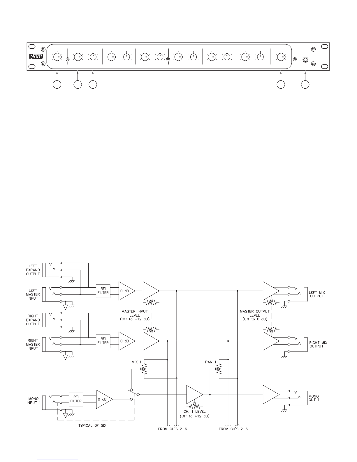
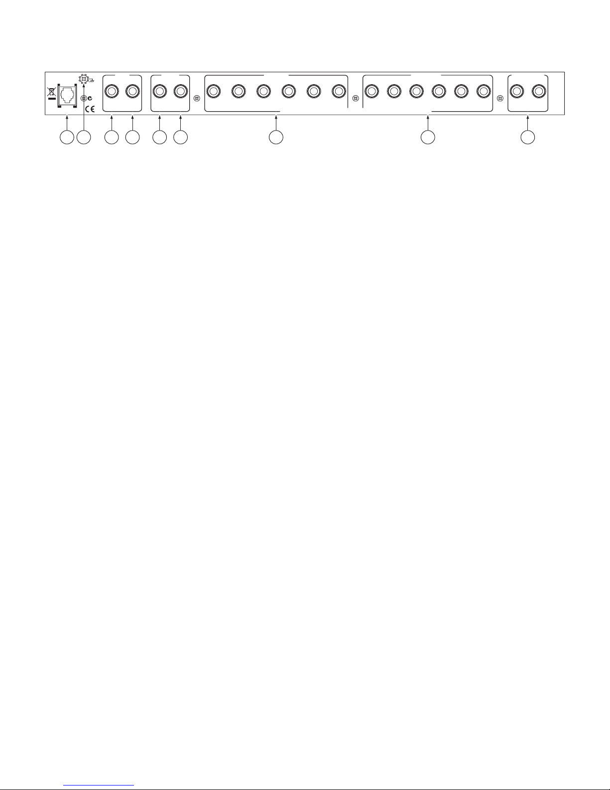
1Master LEFT & RIGHT INPUTS are balanced Tip-Ring-Sleeve (TRS) ¼" Inputs. ese Inputs feed all six MONO OUTs
when all MONO INs are not used. Connecting to individual MONO INs disconnects that channel from these Inputs (refer to the
Block Diagram found on the SM 26B Data Sheet). For unbalanced operation use a standard mono ¼" plug; for balanced opera-
tion use a TRS (stereo) ¼" plug wired as follows:
TIP is signal + (connect to Pin 2 on a 3-pin connector).
RING is signal - (pin 3 in a 3-pin connector).
SLEEVE is chassis ground.
2LEFT & RIGHT EXPAND OUTS: ¼" TRS jacks are connected in parallel with the Master LEFT & RIGHT INPUT jacks,
allowing two or more SM 26Bs to be daisychained for multiple splitting. Simply connect these EXPAND OUTS to the LEFT &
RIGHT INPUTs of another SM 26B; there is no limit to the number of expansions possible with the SM 26B.
NOTE: ese Expand Outputs are not buffered from the Master Inputs. erefore it is not possible to mix both balanced and
unbalanced lines in the same channel between several units: once the ring and sleeve are shorted anywhere in the chain (by using a
mono plug) the entire line becomes unbalanced.
3MONO INPUTS are TRS ¼" jacks which accept either balanced or unbalanced mono signals. ese are switching jacks which
automatically bypass the Master LEFT & RIGHT INPUTs whenever a plug is inserted (see the Block Diagram in the SM 26B
Data Sheet). Follow wiring conventions as in 1.
4MONO OUTPUTS: ¼" TRS jacks deliver either a conventional unbalanced output (use mono cords), or a balanced output (use
TRS cords). Follow wiring conventions as in 1.
5LEFT & RIGHT MIX OUTPUTS: ese balanced TRS ¼" outputs are controlled by the MASTER OUTPUT LEVEL
control. ey are fed either by the Master LEFT & RIGHT INPUTS (respectively) or by any of the six MONO INPUTS, or a
combination of both (see e Swiss Army Mixer RaneNote). Follow wiring conventions as in 1.
6Remote power supply input: e SM 26B is supplied from the factory with a model RS 1 Remote Power Supply suitable for con-
nection to this input jack. e power requirements of the SM 26B call for a 18-24 volt AC center-tapped transformer only. is is
not a telephone jack. Never use a power supply with your SM 26B other than the one supplied or a Rane approved replacement.
7Chassis ground point. A #6-32 screw is used for chassis grounding purposes. See the Chassis Grounding note below.
CLASS 2 EQUIPMENT
MADE IN U.S.A.
RANE CORP.
300mA
POWER
SM 26B
ACN 001 345 382
ALL INPUTS AND OUTPUTS ARE BALANCED — TIP=POS RING=NEG SLEEVE=CHASSIS GROUND
EXPAND
OUT
INPUT
LEFT
EXPAND
OUT
INPUT
6
RIGHT
543
MONO IN
12 1 6 5 4 3 2
MONO OUT
LEFT RIGHT
EXP. OUT
INPUT
EXP. OUT
INPUT
6 5 4 3 12 1 6 5 4 3 2
LEFT RIGHT
MIX OUTPUT
6 1 2 1 2 3 4 57
CHASSIS GROUNDING
If after hooking up your system it exhibits excessive hum or buzzing, there is an incompatibility in the grounding configuration
between units somewhere. Your mission, should you accept it, is to discover how your particular system wants to be grounded. Here
are some things to try:
1. Try combinations of lifting grounds on units that are supplied with ground lift switches or links.
2. If your equipment is in a rack, verify that all chassis are tied to a good earth ground, either through the line cord grounding pin or
the rack screws to another grounded chassis.
3. Units with outboard power supplies, such as the SM 26B, do not ground the chassis through the line cord. Make sure that these
units are grounded either to another chassis which is earth grounded, or directly to the grounding screw on an AC outlet cover by
means of a wire connected to a screw on the chassis with a star washer to guarantee proper contact.
Please refer to the “Sound System Interconnection” RaneNote for further information on system grounding.