Rane TTM 57SL User manual

1xxxx SCRATCHLIVE TTM 57SL OPERATORS MANUAL 1.8.0

Introduction
Please read this manual to get the most from your TTM 57SL
and the included Scratch LIVE software. If you ever lose this, a
new copy may be downloaded at www.rane.com/ttm57sl.html.
To keep up with the latest tips and software updates, visit the
Official Scratch LIVE Forum at scratchlive.net.
Minimum system requirements
Mac
Windows
Note: is is the minimum requirement to run Scratch LIVE
recommend a higher spec computer, and particularly if you
Note: No sound card is necessary.
Check List
LIVE software install disc.
Copyright notices
LIVE and
the Scratch LIVE
-
-
Important Safety Instructions
with manufacturer’s instructions.
grounding prong. e wide blade or third prong is provided for
your safety. If the provided plug does not fit into your outlet,
consult an electrician for replacement of the obsolete outlet.
pinched particularly at plugs, convenience receptacles, and the
specified by the manufacturer, or sold with the apparatus.
apparatus combination to avoid injury from tip-over.
unused for long periods of time.
required when the apparatus has been damaged in any way,
such as power supply cord or plug is damaged, liquid has been
spilled or objects have fallen into the apparatus, the apparatus
normally, or has been dropped.
device and must remain readily operable.
with a protective earthing connection.
incorporated in the electrical installation of the building.
may be located above or below this apparatus, but some
unacceptable amount of hum or may generate too much heat
and degrade the performance of this apparatus.
provide the best support.
WARNING
liquids, such as vases, shall be placed on the apparatus.
RISK OF ELECTRIC SHOCK
DO NOT OPEN
CAUTION
To reduce the risk of electrical shock, do not open the unit.
service personnel.
e symbols shown below are internationally accepted symbols that
is symbol indicates that a dangerous voltage
constituting a risk of electric shock is present
within this unit.
is symbol indicates that there are important
operating and maintenance instructions in the
literature accompanying this unit.
WARNING

1
TTM 57SL MIXER
OPERATOR’S MANUAL
Scratch LIVE Version 1.8
Contents
TTM 57SL: The Hardware .................................... 3
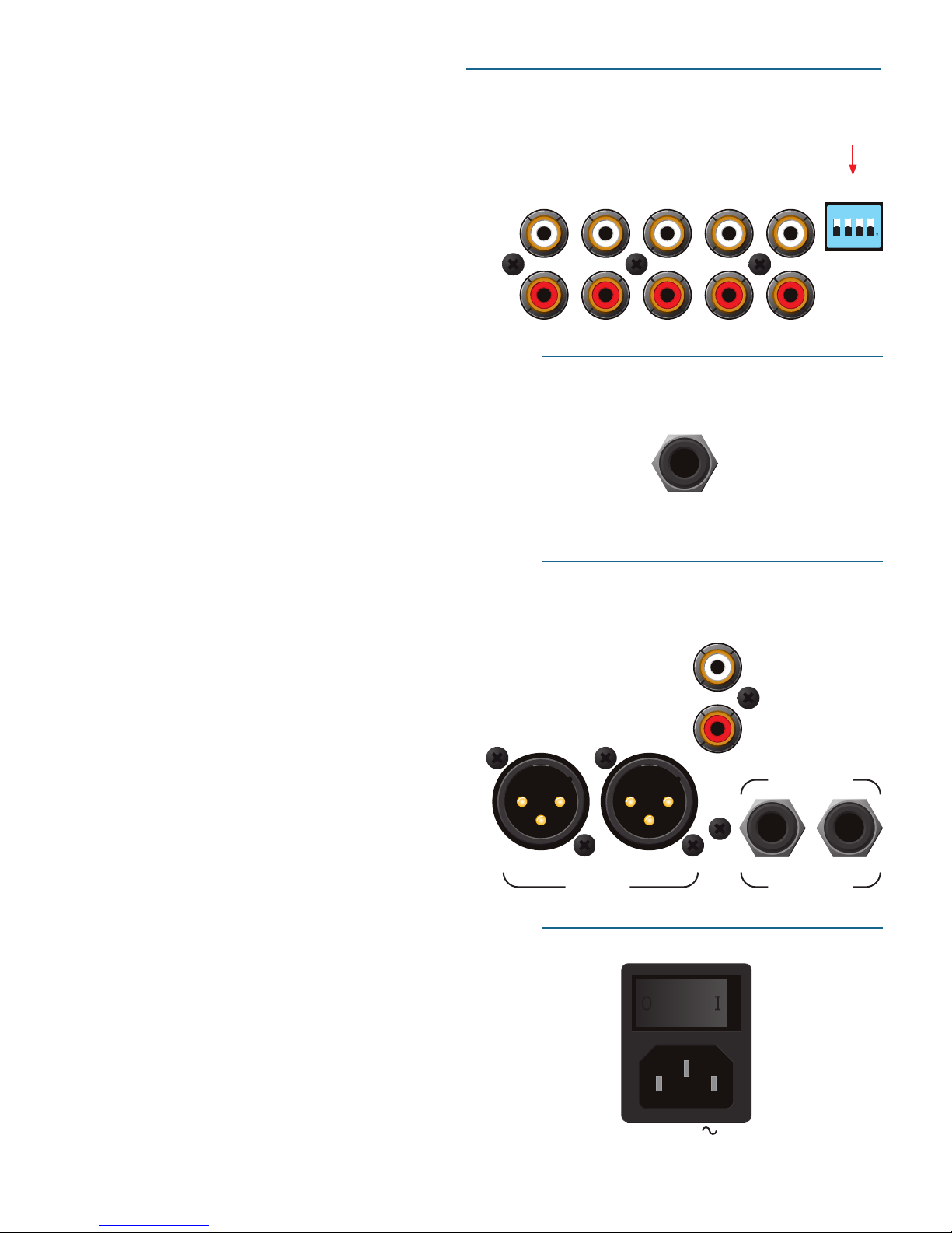
Connecting the Mixer.......................................... 3
PGM Inputs 1-4 and Aux Input ......................... 3
Mic Input ......................................................... 3
Outputs ........................................................... 3
Power Supply ................................................... 3
Program controls................................................. 4
INPUT .............................................................. 4
GAIN................................................................ 4
PAN ................................................................. 4
HIGH / MID / LOW EQ ...................................... 4
Faders.............................................................. 5
CONTOUR........................................................ 5
REVERSE.......................................................... 5
CHANNEL SWAP............................................... 5
METER ............................................................. 5
AUX IN............................................................. 6
MIC LEVEL and EQ ........................................... 6
OUTPUT LEVELS............................................... 6
PHONES........................................................... 6
CUE ................................................................. 6
MASTER CUE.................................................... 6
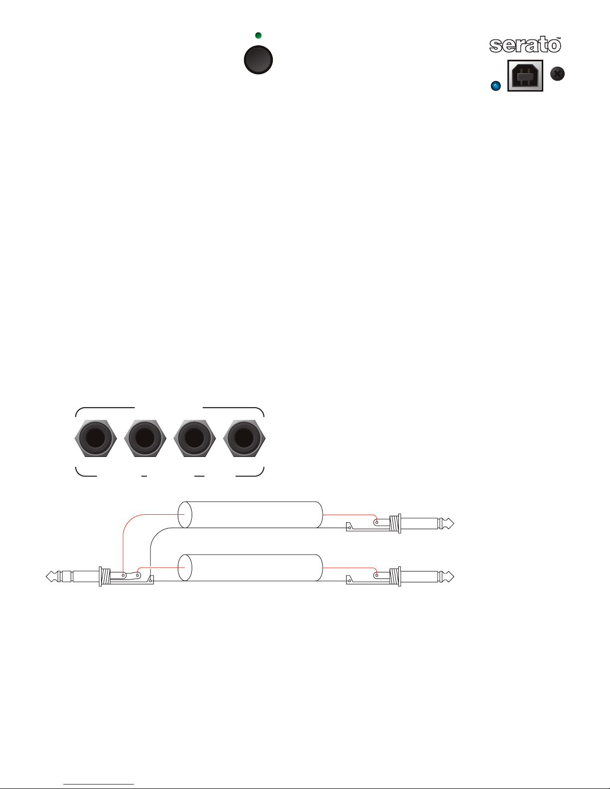
FlexFX Loop ..................................................... 7
USB Streaming Audio ....................................... 7
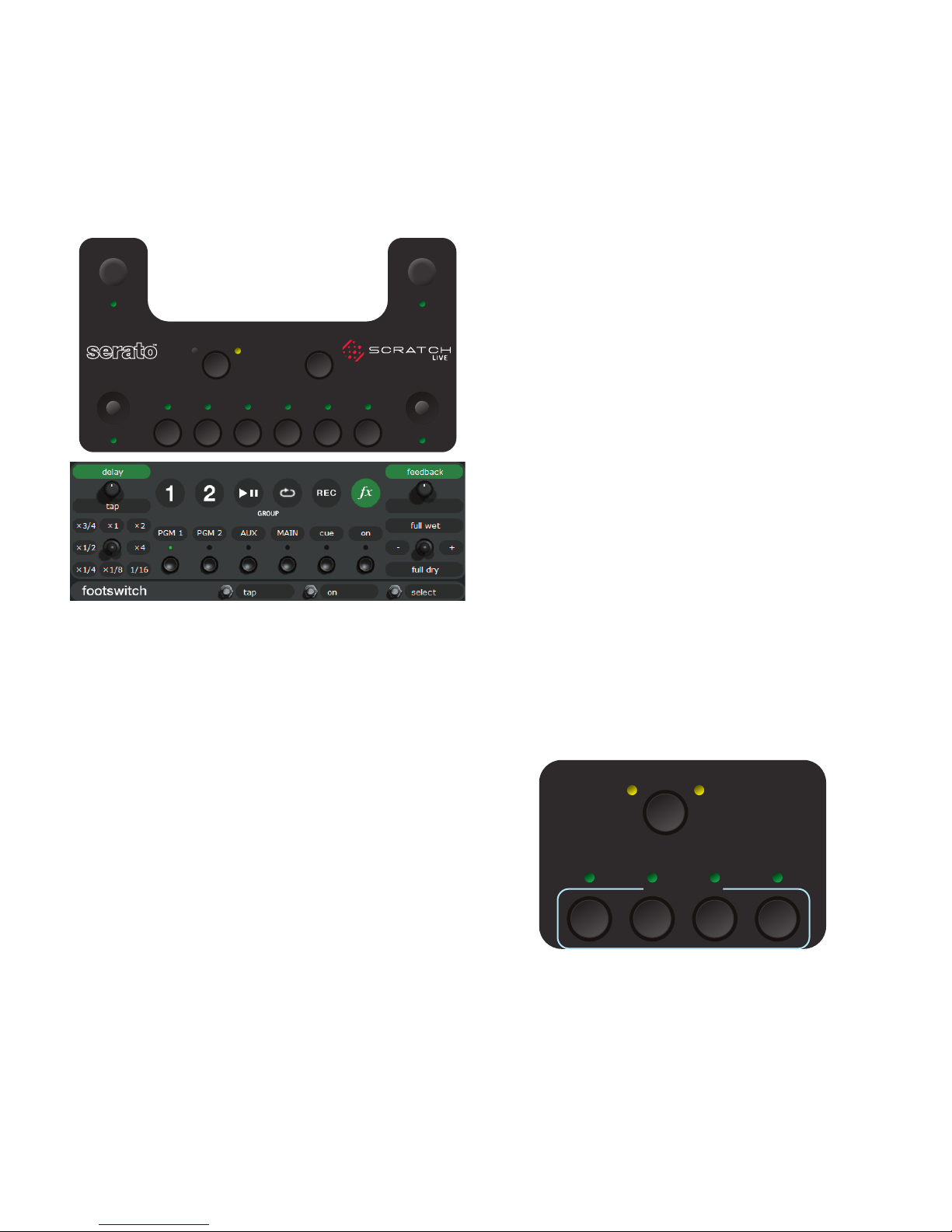
Effects: Hardware and Software Control Panels ... 8
Internal Digital Effects ..................................... 8
Inserting an Effect ........................................... 8
Basic Effects Controls....................................... 9
Footswitch....................................................... 9
Effects Cueing.................................................. 9
Controls for Filter Effects ............................... 10
Controls for Flanger and Phaser Effects.......... 10
Controls for Echo Effects................................ 12
Controls for Hold Echo Effects........................ 13
Controls for Desecrator Effect ........................ 14
Scratch LIVE: The Software................................ 15
Install the software / Connect the mixer......... 15
Setting up your turntables ............................. 16
Using tool tips ............................................... 16
Calibrating Scratch LIVE.................................... 17
Audio output ................................................. 17
Signal threshold............................................. 17
Scope view..................................................... 17
Playing your first track...................................... 18
Loading tracks ............................................... 18
Supported file types ....................................... 18
Preparing your files........................................... 18
Build overviews ............................................. 18
Set auto BPM ................................................. 18
Reset track gain ............................................. 18
Offline Player.................................................... 18
Playing tracks ................................................... 19
The control record.......................................... 19
Vinyl Scroll..................................................... 19
Virtual Deck ................................................... 19
Visual aids ..................................................... 20
Tempo, track, main & beat matching displays . 20
Tracking indicator .......................................... 22
Autoplay........................................................ 22
Master gain.................................................... 22
Track gain ...................................................... 22
Key Lock........................................................ 22
33 / 45 Speeds............................................... 22
Repeat ........................................................... 22
Tap Tempo ..................................................... 22
Scratch LIVE modes........................................... 23
Absolute mode............................................... 23
Relative mode ................................................ 23
Censor ........................................................... 23
Internal mode ................................................ 24
Cue points ........................................................ 25
Looping ............................................................ 25
Auto-looping..................................................... 25
MIDI Control ..................................................... 26
MIDI controller setup...................................... 26
Assigning Controls ......................................... 26
Presets ........................................................... 26
MIDI implementation...................................... 26
Organizing your music ...................................... 27
Grouping tracks into crates ............................ 27
Subcrates ....................................................... 27
Sorting your files ........................................... 27
Using the song browser .................................... 28
Searching....................................................... 28
Prepare window ............................................. 29
Review window ............................................. 29
Editing ID3 tags............................................. 29
Status icons ................................................... 29
Display album art........................................... 29
Playing tracks direct from audio CD................ 29
Previewing tracks........................................... 29
Autobackup ................................................... 29
Recording ......................................................... 30
Keyboard shortcuts ........................................... 31
Additional setup ............................................... 32
Hardware....................................................... 32
Playback ........................................................ 33
Vinyl control .................................................. 34
Library ........................................................... 34
Display........................................................... 35
Plugins .......................................................... 35
USB dropout indicator.................................... 35
The hardware control panel .............................. 36
Controlling Scratch LIVE from the TTM 57SL... 36
Groups........................................................... 36
Customizing the control assignments ............. 36
Group details ................................................. 37
Mixing with only one turntable......................... 40
TTM 57SL specifications .................................... 40
Troubleshooting and FAQ.................................. 41
Scope reading and fixes .................................... 42
Corrupt file descriptions and diagnoses............. 44
Magnetic fader maintenance ............................. 45
Appendix: DSP and analog block diagrams........ 47
Foot switch diagram ......................................... 48

2
TTM 57SL Mixer Overview
-
-
hardware and Serato Scratch LIVE, creating a whole new range of
possibilities for your performance. e TTM 57SL was specifically
designed to work with Scratch LIVE and the available features are
best served when used with Scratch LIVE. e TTM 57SL is also a
very competent standalone performance mixer.
Future proof
each new release of the Scratch LIVE software – and all Scratch
LIVE updates are free.
Scratch LIVE control surface
LIVE
Navigate though your library, load tracks, hit cues, loop and
an input for connecting a Footswitch for hands free looping,
Eects
live sound software technologies give you professional studio-
Advanced recording capabilities
External sound card interface
-
Magnetic faders
accurate, and longest lasting on the planet. e TTM 57SL uses
the same faders and performance oriented layout that made the
Hardware features
control.
audio.
TURNTABLE OUTTURNTABLE OUT
DUAL CD PLAYER OUTS
GROUND
GROUND
USB
+12-12
+12-12
10 OL
0
2
4
8
6
100
RL +6OFF
100
64
28
64
28
100
64
28
OL
+8
+4
+2
0
–4
–2
–8
–16
–24
PERFORMANCE MIXER
100
64
28
100
64
28
+6OFF
+6OFF
+15-15
A
D
A
D
RL
+6OFF
+6OFF
+6OFF
+15-15
MIC LOW
MIC HIGH
MIC LEVEL
OUTPUT
LEVELS
MAIN
INPUT
BOOTH
PAN
HIGH
AUX OUT
MID
GAIN GAIN
PHONES
METER
LOW
HIGH
MID
LOW
PGM 2PGM 1
TTM 57SL
A B
PGM 1CUE PGM 2
SLOW
FADER 1 CONTOUR
FAST SLOW
FADER 2 CONTOUR
FASTSLOW
CROSSFADE CONTOUR
FAST
FlexFX
PAN
FlexFX
GROUPDECK
AUX IN
P1
2
1
INPUT
P2
2
1
J1
B1 B2
12
B3 B4 B5 B6
J2
CHANNEL
SWAP
MIC ON
STEREO
HOUSE
MASTER
CUE
REVERSEREVERSE
REVERSE
RECORDS
CONTROL RECORD
This record contains a control signal only
and is intended solely for use in conjunction
with Serato Scratch LIVE software.
©2004Serato Audio Research
©2004Rane Corporation
Allrights reserved.
14368
10:00
CV02
12-125-33
A
RECORDS
CONTROL RECORD
This record contains a control signal only
and is intended solely for use in conjunction
with Serato Scratch LIVE software.
©2004Serato Audio Research
©2004Rane Corporation
Allrights reserved.
14368
15:00
CV02
12-125-33
B

3
AUX
PGM 1PGM 2
4321
IN
R
L
R
L
R
L
R
L
PHONO
LINE
4321
ON
MAIN BOOTH
AUX
LEFTLEFTRIGHT
BALANCED
OUT
RIGHT
MIC
BALANCED
INPUT
POWER
100-240V
50/60 Hz
20 WATTS
TTM 57SL: The Hardware
e best way to understand the TTM 57SL is to learn the basic
learn Scratch LIVE
Connecting the Mixer
Leave the power unplugged until everything else is connected!
PGM Inputs 1-4 and Aux Input
switches located on the rear panel. Up is LINE and down is
-
-
sible to select any combination of digital and analog signals.
LIVE
Scratch LIVE
for Scratch LIVE
are selected using the Scratch LIVE
emulation control by the Scratch LIVE software, the number is
back-lit as a reminder that the source is selected for control.
Mic Input
Analog Outputs
for system connection.
and rejection of hum and noise. If your cable to the amp rack
-
www.rane.com for details and cable wiring.
Power Supply
e TTM 57SL features an internal universal switching power
Set the unused inputs to LINE.

4
Program
Controls
INPUT
INPUT
sources for each Program.
PGM 1
A1
A2
D1
D2
PGM 2
A3
A4
D1
D2
LIVE
software.
12is illuminated, the
Input has been selected by the Scratch LIVE software
as the vinyl emulation input for Deck One. If the
34is illuminated, the Input has
been selected by Scratch LIVE as the vinyl emulation
input for Deck Two. e backlit number is a reminder that this
source may be a control signal and not audio. You may select a
control input and use it as a normal analog input at any time
without de-selecting it for control in Scratch LIVE, but remember
you will hear the
control signal.
GAIN
inputs. ese controls have a built-in Limiter that prevents the
-
PAN
HIGH / MID / LOW EQ
e control range is OFF to +6nd
Accelerated Slope™ filters. e Low-
operation within the Scratch LIVE software.
See latch kill switches
Interactivity of the Accelerated-Slope
AUDIO PRECISION AMPL (dBr) vs AMPL (dBr)
-40
-35
-30
-25
-20
-15
-10
-5
0
5
10
G
A
I
N
FREQUENCY
20 100 1k 10k 20k
LOW–
MID–
HIGH–
LOW+
MID+
HIGH+
RL +6OFF
+6OFF
+6OFF
A
D
A
D
RL
+6OFF
+6OFF
+6OFF
100
2
4
8
6
100
2
4
8
6
INPUT
PAN
HIGH
MID
GAIN GAIN
LOW
HIGH
MID
LOW
FlexFX
PAN
FlexFX
2
1
INPUT
2
1

5
Faders
-
CONTOUR
ese controls provide a full range of fader adjustment from
CHANNEL SWAP
is button reverses the channel assignment for all three faders.
Aside of
B
recessed to prevent accidental engagement.
METER
e Meter has two modes of operation. e METER switch
toggles between dual mono CUE and STEREO HOUSE
e Meter displays loudness with a solid string of lights, and how
close you are to clipping with a moving dot. If the red OL indica-
On = Stereo House Metering
O = Dual Mono Cue Metering
0
20
40
60
80
100
Channel and CrossFader Contour
travel
dB Attenuation
SLOW
FAST
REVERSE
ese switches are provided for each fader just to the right of each
push of the switch. ese switches are slightly recessed to prevent
accidental engagement.
OL
+8
+4
+2
0
–4
–2
–8
–16
–24
PERFORMANCE MIXER
METER
TTM 57SL
A B
SLOW
FADER 1 CONTOUR
FAST SLOW
FADER 2 CONTOUR
FASTSLOW
CROSSFADE CONTOUR
FAST
CHANNEL
SWAP
STEREO
HOUSE
REVERSEREVERSEREVERSE

6
+12-12
+12-12
10
OL
0
2
4
8
6
100
64
2 8
MIC LOW
MIC HIGH
MIC LEVEL
AUX IN
MIC ON
100
100
64
28
64
28
100
64
28
100
64
28
OUTPUT
LEVELS
MAIN
BOOTH
AUX OUT
PHONES
PGM 1 CUEPGM 2
MASTER
CUE
AUX IN
MIC LEVEL and EQ
e MIC ON switch engages the Mic. e green indicator is lit
MIC LEVEL
e OL indicator lights when the signal reaches clipping. If
MIC HIGH and MIC LOW tone controls allow you to
OUTPUT LEVELS
Output Level controls are provided for MAIN, BOOTH and
AUX
-
jacks allows you to hook into other equipment regardless of the
connector type.
Headphone Cueing
simultaneously, but using only one at a time yields more power to
the headphones.
PHONES
e headphone output can deliver very high volume to some
headphones. To avoid pain, never put headphones on your head
before plugging them in
turned down, and then turn it up to the desired level.
CUE
off
is on
pre-fader.
MASTER CUE
on
off HEADPHONES
(XLR)
(TRS)
(RCA)

7
FlexFX Loop
-
loop. is allows a single external
-
signal to the external
cable, as shown below.
-
connected.
-
USB
USB Streaming Audio
ere are eight channels of streaming audio
the computer and two stereo channels to the
device is connected and communicating with the computer. For
Two stereo signals from
emulation control, one stereo pair can also be sent to your com-
LIVE
as two four-channel sound cards with stereo in and stereo out.
e source for the stereo output channels must be selected in
your software.
e following signals may be selected as the source for either
1-CONDUCTOR SHIELDED CABLE
T = SEND
R = RETURN
S = SHIELD
++SEND
RETURN
++
SHIELD SHIELD
SHIELD
Send/Return Cable Wiring
FlexFX
RETURN SEND
RIGHT LEFT
UNBALANCED
LEFTRIGHT
FlexFX

8
Effects
Hardware and software control panels
Serato Scratch LIVE software. ese also control the Internal
the Scratch LIVE software or when using the TTM 57SL stand-
alone. Scratch LIVE
Internal Digital Effects
they are available for signal processing even when Scratch LIVE is
LIVE
assignment or settings.
Scratch LIVE software eect controls mirror the TTM 57SL front panel.
When one status changes, so does the other.
GROUPDECK
P1 P2
J1
B1 B2
12
B3 B4 B5 B6
J2
DECK
B1 B2
12
B3 B4
PROCESSOR 1 PROCESSOR 2
PGM 1 PGM 2AUX MAIN
INSERT POINT
with Scratch LIVE software to learn control assignments. Typically,
stand-alone operation simple. e TTM 57SL ships with Echo
LIVE
reassigns them. Note: these defaults can be changed and saved to the
mixer with the Hardware Setup screen shown on page 32.
Group 6
If you are connected to the Scratch LIVE software, switch to
Inserting an Effect
PGM 1, PGM 2, AUX BUS or Main Mix
Processors can use the same insert point, but the order depends
Note: Any Echo Effect can only be loaded into one of the
processors.
-
mine it’s insert point are shown below. e DECK button selects
to be controlled. Pressing the button toggles
B1
B2
B3
B4
Inputs.

9
Basic Effects Controls
PGM 1 CUE
PGM 2 CUE
MAIN MIX CUE
CUE
PGM 1 EFFECT CUE
PGM 2 EFFECT CUE
MAIN MIX EFFECT CUE
AUX BUS EFFECT CUE
MASTER CUE
CUE PAN
ON
OFF
Eects Cue Logic Diagram
B5 B6
J2
ON ON
CUE EFFECT
TRANSFORM
B5
B6
J1 and J2 joysticks may operate as transform switches or be used
J1 and J2 each feature an eight-
position joystick, a push switch and a green mode indicator light.
off, the associated joystick operates as a
transform switch.
on, the joystick is assigned to an
the joystick toggles between the two modes of operation. If a
second function is not available, pressing the joystick has no
switch joystick modes.
P1 and P2-
sisting of a rotary encoder, a push switch and a green mode light.
Footswitch
-
e footswitch can also assist with looping and recording
Effects Cueing
B5 turns
on
B1
B5
B6
on.
the headphones unless it is on and also sent to the Master.
New Effects in 1.8
Phaser:
Flanger:
peak delay change.
Desecrator:
HP Echo and HP Hold Echo:

10
GROUPDECK
P1 P2
J1
B1 B2
12
B3 B4 B5 B6
J2
PROCESSOR 1
FREQUENCY RESONANCE
DEPTHTAP BPM
PROCESSOR 2MULTIPLIER
PGM 1 PGM 2AUX B MAIN ON ON
INSERT POINT CUE EFFECT
ALL WET
MORE
DRY
ALL DRY
MORE
WET
1
¾
¼8
2
½
16
4
P1
•Frequency31.5 Hz 16 kHz
Sweep
max 3.0
min 0.7
•
P2P1
•
single
tap BPM
sync
point,
multiple
taps to set BPM.
Depthmin
•
P2
Resonance
P1
•Frequency31.5 Hz 16 kHz
Sweep
min 0.7
max 6.0
•
P2
Resonance
•
P2P1
•
single
tap BPM
sync
point,
multiple
taps to set BPM.
Depthmin
P1
•Frequency31.5 Hz 16 kHz
Sweep
•
P2
max 3.0
min 0.7
P1
•
single
tap BPM
sync
point,
multiple
taps to set BPM.
Depthmin
•
P2
Resonance
LP Filter Eect Response BP Filter Eect Response HP Filter Eect Response
Control Assignments for Sweep Filter Effects
Each Filter’s settings are independent from the other Filters.
P1 Frequency / Tap BPM
-
es it and a lock icon appears in the Filter section. To manually
P1
and tapping P1
P1
e primary function of P1off-
rotations of P1.
J1 Multiplier
J1, which toggles between
indicator is on, J1
P2 Resonance / Depth
P2-
tor off
each Filter type.
P2
indicator on
P1. e
J2 Wet / Dry
off
on
-

11
GROUPDECK
P1 P2
J1
B1 B2
12
B3 B4 B5 B6
J2
PROCESSOR 1
PHASER FREQUENCY
or FLANGER DELAY
FEEDBACK
DEPTHTAP BPM
PROCESSOR 2MULTIPLIER
PGM 1 PGM 2AUX B MAIN ON ON
INSERT POINT CUE EFFECT
ALL WET
MORE
DRY
ALL DRY
MORE
WET
1
¾
¼8
2
½
16
4
P1
•Frequency
All-pass lter
31.5 Hz16 kHz
Sweep
•
P2P1
•
single tap
BPM sync
point,
multiple
taps to
set BPM.
Depthmin
•
P2
Feedback
range = 0 to 100%
B6
•
on
P1
•Base Delay
Base Delay
Delay
0 sec11.6 ms
P2
•
Delay Depth
Sweep
P1
•
single tap
BPM sync
point,
multiple
taps to
set BPM.
•
P2
Feedback
range = 0 to 100%
B6
•
on
Phaser Eect Diagram
Flanger Eect Diagram
Control Assignments for Phaser & Flanger
relationship between the comb teeth. Splitting an audio signal in
two, shifting the phase of one signal by passing it through an all-
of equally spaced notches in the the frequency spectrum in a
a slightly delayed copy of itself and by constantly changing the
length of the delay.
to sweep up and down the frequency spectrum.
P1 Phaser Frequency / Flanger Delay / Tap BPM
e Phaser’s primary function of P1off
P1.
e Flanger’s primary function of P1off
P2
P1
and tapping P1
P1
J1 Multiplier
J1, toggling between trans-
is on, J1
P2 Feedback / Depth
Feedback is the primary function of P2off
the amount of phased or delayed signal fed back to the input, in-
P2.
P2
indicator on
P1
-
P2
P1 becomes a manual
sweep control.
J2 Wet / Dry Mix
off
on
-

12
Control Assignments for Echo Effects
and a lock icon appears in the Echo section. To manually set the
P1
J1 Multiplier
Pressing J1-
tor offon
green indicator lit, J1
function and are grayed-out in the software control panel. If
-
P1 Delay / Tap BPM
Once you turn P1, the lock icon disappears, the Multiplier
number turns white and P1
-
multiplier with J1, and the Multiplier number changes to green.
P1
P2 Feedback
Feedback is the amount of delayed signal fed back to the delay
P2.
changing the insert point does not clear the feedback loop. is
clear the loop and start a fresh Echo immediately, rapid double-
Echo Effect
P2
GROUPDECK
P1 P2
J1
B1 B2
12
B3 B4 B5 B6
J2
HP Echo Effect
P2on
J2 Wet / Dry
Pressing J2off
on
-
-
P1
•
Delay
B1
PGM 1
•
B2
PGM 2
•
B3
AUX
•
B4
MAIN
•
PGM 1
PGM 2
AUX
MAIN
B6
•
Delay is set by BPM tag.
Tap
P1
•
for manual BPM.
•
P2
Feedback
range = 0 to 94%
Echo starts to
build when eect
is inserted
on
B1
•
B2
•
B3
•
B4
•
B1
PGM 1
•
B2
PGM 2
•
B3
AUX
•
B4
MAIN
•
PGM 1
PGM 2
AUX
MAIN
B6
•
Delay is set by BPM tag.
Tap
P1
•
for manual BPM.
•
P2
Feedback
range = 0 to 94%
Echo starts to
build when eect
is inserted
on
B1
•
B2
•
B3
•
B4
•
P1
•
Delay
P2
•
Frequency
HP Filter
Echo Eect Signal Flow
HP Echo Eect Signal Flow

13
Control Assignments for Hold Echo Effects
and a lock icon appears in the Echo section. To manually set the
P1
J1 Multiplier
Pressing J1-
tor offon
green indicator lit, J1
function and are grayed-out in the software control panel. If
-
P1 Delay / Tap BPM
Once you turn P1, the lock icon disappears, the Multiplier
number turns white and P1
-
multiplier with J1, and the Multiplier number changes to green.
P1
P2 Feedback
Feedback is the amount of delayed signal fed back to the delay
P2.
changing the insert point does not clear the feedback loop. is
clear the loop and start a fresh Echo immediately, rapid double-
Hold Echo Effect
P2.
and B6 is on.
B6 is off.
will loop for days. e loop will decay if Feedback is reduced.
P2
GROUPDECK
P1 P2
J1
B1 B2
12
B3 B4 B5 B6
J2
HP Hold Echo Effect
P2on
J2 Wet / Dry
Pressing J2off
on
-
-
P1
•
Delay
B1
PGM 1
•
B2
PGM 2
•
B3
AUX
•
B4
MAIN
•
PGM 1
PGM 2
AUX
MAIN
Delay is set by BPM tag.
Tap
P1
•
for manual BPM.
•
P2
Feedback
range = 0 to 100%
Echo starts to
build when eect
is inserted and on
B6
•
on
B1
•
B2
•
B3
•
B4
•
P1
•
Delay
B1
PGM 1
•
B2
PGM 2
•
B3
AUX
•
B4
MAIN
•
PGM 1
PGM 2
AUX
MAIN
Delay is set by BPM tag.
Tap
P1
•
for manual BPM.
•
P2
Feedback
range = 0 to 100%
Echo starts to
build when eect
is inserted and on
B6
•
P2
•
Frequency
on
B1
•
B2
•
B3
•
B4
•
HP Filter
Hold Echo Eect Signal Flow
HP Hold Echo Eect Signal Flow

14
GROUPDECK
P1 P2
J1
B1 B2
12
B3 B4 B5 B6
J2
PROCESSOR 1
DRIVE LEVEL SAMPLE RATE
BIT DEPTH
PROCESSOR 2
PGM 1 PGM 2AUX B MAIN ON ON
INSERT POINT CUE EFFECT
ALL WET
MORE
DRY
ALL DRY
MORE
WET
P1
•
Drive
Level
B6
•
P2
•
Sample
Rate
P2
•
Bit
Depth
44.1 kHz
to 34 Hz
3 to
24 bits
Inverse
Drive
Level
on
Desecrator Eect Diagram
Control Assignments for Desecrator
rusty metal spikes, by allowing adjustment of bit-depth and
fine shave, or enough for a wig!
P1 Drive Level
e only function of P1off
slight level reduction occurs when clipping.
P1
J1
P2 Sample Rate / Bit Depth
P2off-
P2
indicator on
P1
when bits are reduced to a single digit.
J2 Wet / Dry Mix
off
on
-

15
The Software:
Getting started
1) Install the software
Mac
installer icon.
Windows
setup.exe. Notecustom install to change the directory
you wish to install Scratch LIVE into.
complete, Scratch Live appears in the Start Menu under All
Programs > Serato > Scratch Live.
2) Connect the TTM 57SL mixer
Mac
-
Windows XP Drivers
driver that allows you to use your TTM 57SL as a sound card.
e second driver allows you to use the TTM 57SL with Scratch
LIVE.
proceed to install the Scratch LIVE driver.
Vista Drivers
LIVE driver.
Installing the Scratch LIVE driver.
LIVE
Scratch LIVE.
No, not this timeNext
Install the software automatically
Next
Continue Anyway
Finish.
TTM 57SL as a sound card
card whenever Scratch LIVE is not running. It will replace the
previous sound card and default to TTM57SL Line 2 D 2 on
either of the PGM INPUTS
If you wish to change to Line 1 or back to your previous
Start > Control Panel > Sounds and Audio Devices.
Audio tab.
Sound Playback
and Sound Recording.
OK.
Tip
card. To prevent embarrassment, have no other applications run-
Start > Control Panel > Sounds and Audio Devices.
Sounds tab.
Sound scheme, change to No Sounds.
OK.

16
Setting up your turntables
cartridge used, such that the needle never leaves the record, but
poor tracking.
cables. e inputs from your turntables might be the wrong
LIVE.
Make sure you have good connections from the ground wires
points for this purpose. If you do not ground your turntables
properly, the control signal will be noisy and the tracking of
signal threshold on
Tip: We recommend Shure M44-7 needles for use with Scratch
LIVE, due to their high output volume, excellent tracking
and low record wear.
Starting the software
Scratch LIVE for the first time, you will see the screen below.
Troubleshoot: The TTM 57SL mixer is not recognized
It takes five seconds for Scratch LIVE to detect the TTM 57SL.
Scratch LIVE before disconnecting the hardware. In some situa-
and re-plugging in the TTM 57SL for Scratch LIVE
-
separately, so you will need to install the driver separately for each
Using tool tips
?
icon to enable tool tips. Tool tips provide a handy
way to learn the various features of Scratch LIVE. Move the mouse
?
button with tool tips turned
on will show you a list of all keyboard shortcuts.
Tool tips are available in several languages. Scratch LIVE will
display the tool tips in the language that your computer is set to.
If your language is not available, the tool tips will be displayed in
English.

17
Calibrating Scratch LIVE
e TTM 57SL interprets the signal on record and communi-
cates with the software. e signal needs to be clear for Scratch
LIVE to perform well. is section describes how to calibrate
Scratch LIVE
For best results, re-calibrate Scratch LIVE each time you move
LIVE, go to the setup screen by pressing the button at the top of
the main screen, to the right of the Scratch LIVE logo.
Signal threshold
e first step is to set signal threshold. ere is always a certain
amount of background noise, particularly when using turntables
-
ground noise is transmitted through the body of the turntable
and platter to the stylus, and can cause stylus feedback. In Scratch
LIVE, this can cause errors on the reading of the position and
velocity of the control record, resulting in a garbled digital noise
Place the needle on the record with the record stopped.
estimate button to measure the background noise and
estimate the appropriate threshold. Moving the threshold slider
to the left will make Scratch LIVE more sensitive to slow record
movement, but also more sensitive to background noise.
Tip: If the slider jumps to the far right, then you have a prob-
lem with noise in your turntables/CD players/mixer. Check all your
connections and make sure your equipment is well earthed. In some
situations you will not be able to improve the signal quality, and
you will have to play on regardless. In this situation, stick to relative
mode. (See page 23 for details)
Scope view
Once you have set the threshold, start both turntables. You will
see green rings appear in the scope view, as shown below.
For optimal performance the inner ring should be as close
1x to 16x
L/R balance and P/A
balance controls to adjust the shape of the inner ring.
e number in the top left corner of the scope view gives the
the bottom left is the current threshold setting, and the number
in the bottom right shows the percentage of readable signal – this
properly.
Tip: If you have trouble getting the rings circular, you probably
need to clean or change your needles. If the image appears as a line,
then one of the channels of the turntable is not working. See examples
of potential problems and fixes on pages 42-43.

18
Playing your first track
Now that you have calibrated Scratch LIVE, you are ready to play
setup screen later to set
general system preferences.
LIVE, your library contains only
the pre-installed tracks. Load files into Scratch LIVE by pressing
the import button. Navigate the hard drive of your computer to
✽ All
…
icon.
You can also import by dragging files and folders directly
into the Scratch LIVE
Scratch LIVE
Loading tracks
✽ All… icon to show all the tracks in your library.
To load a track on to one of the decks, drag the track from the
track list on to either deck. You can drag the same track on to
both decks to load it onto both turntables.
Tip: Use the keyboard shortcut shift to load the highlighted
track on to the left deck, and shift to load the highlighted track on
to the right deck.
To start playing a track, simply put the needle on the record
and start the turntable. e track will start playing from the posi-
tion dictated by the placement of the needle on the record – if
you place the needle at the beginning of the record, the track will
start playing from the beginning. You can skip through the track
by picking up the needle and placing it further into the record,
Supported file types
Scratch LIVE-
playlists can be automatically imported in the setup screen by
clicking read iTunes library. See Rescan 1D3 tags
NOTE: iTunes Music Store DRM-protected files are not able to
be played back using Scratch LIVE.
Preparing your files
Build overviews
If you run Scratch LIVE with the hardware interface disconnected,
you will notice a button labeled build overviews on the main
more bars appear. e first bar shows track reading progress, the
second bar shows overview building, and the third bar shows
track writing progress. is process prepares the overviews of all
your tracks, and alerts you to any corrupt files you might have.
ese are indicated by Status Icons,
Set auto BPM
If this option is checked, building overviews will include the
estimated tempos of your files. If Scratch LIVE is confident that
Note: As auto BPM is part of the overview building process, files
in your library with overviews already built will not be processed
by clicking the build overviews button. To rebuild overviews and
use auto BPM or auto gain on those files, drag them onto the build
overviews button.
Offline Player
e offline player is available when Scratch LIVE hardware is not
connected, and outputs through the current default audio device.
Load a track to the offline player by dragging and dropping onto
the deck, or pressing shift . If the end of the loaded track is
-
cally.
e offline player is a useful tool for preparing crates, audi-
tioning tracks, and setting cue and loop points.
Note: for more information about cue points and looping, see
page 25. For more information on crate organization, see page 27.
Other manuals for TTM 57SL
4
Table of contents
Other Rane Music Mixer manuals