Rane MLM82S User manual

Manual-1
MLM 82S
MIC/LINE MIXER
OPERATORS MANUAL
MLM 82S CONNECTION
When connecting the MLM 82S to other components in your
system for the first time, leave the power cord for last. is gives
you a chance to make mistakes and correct them without dam-
age to your fragile speakers, ears and nerves.
MIC/LINE INPUTS 1-4
e four XLR jacks provided on the MLM 82S are balanced
MIC/LINE inputs. ey will also accept unbalanced connec-
tors. Use only shielded cable for inputs. For best noise rejection
use two-conductor-plus-shielded wire, even for unbalanced
operation. Connect the shield at both ends to help insure proper
grounding. See the Sound System Interconnection RaneNote
included with this manual for all cable adaptations. Rane follows
the AES recommended practice of pin 2 positive, pin 3 negative,
and pin 1 to shield. Switch any input connected to a microphone
to the MIC position (out) using the associated switches on the
rear panel. When connecting line level signals, switch the input
to the LINE position (in). A single phantom power switch is
provided for the four MIC inputs. If LINE is selected, Phantom
Power is disabled for that input.
QUICK START
is section is provided as a convenience for those in a rush. If you are experienced with this unit or other Rane products, these few
words will refresh your memory.
INPUTS 1 through 4 may be microphone or line level. e choice between the two is made by setting the LINE push buttons
on the REAR of the unit next to the MIC/LINE INPUT JACKS. Each microphone input may be assigned to A, Bor A+B outputs
using the front panel ASSIGN switches.
INPUTS 5 through 8are stereo line inputs which may be set to mono using the recessed MONO switches located on the front
panel.
Internal switches allow setting output signal levels for MIC or LINE. e factory default setting is LINE. If the MLM 82S is
connected directly to a power amplifier, equalizer or recorder input, choose LINE level. If the MLM 82S is connected to a micro-
phone jack of an existing sound system, choose MIC level.
Once Inputs, Outputs, and power are properly connected, with the OUTPUT LEVELS counterclockwise (off ), set the Input
LEVELS as high as possible without causing the SIG/OL indicators to blink red except during extreme signal peaks. Now slowly
raise the OUTPUT LEVELS as desired.
STEREO LINE INPUTS 5-8
e ¼" connectors are line-level balanced/unbalanced Inputs.
If the MLM 82S is to be used with unbalanced sources, consult
the Sound System Interconnection RaneNote included with this
manual for proper wiring. Stereo Inputs use both A and B jacks
at each INPUT. INPUTS 5 through 8 also serve as mono Inputs
when the front panel MONO switch is engaged.
OUTPUTS
e MLM 82S’s OUTPUTS are balanced. e same wiring
conventions as the XLR Inputs apply. e type of device follow-
ing the MLM 82S must be considered when setting the internal
Output Level switch. Choose between LINE (0 dB) or MIC (-40
dB) output, the factory setting is LINE. If the MLM 82S is con-
nected directly to a power amplifier input, choose LINE level. If
the MLM 82S is connected to a microphone jack on an existing
sound system, choose MIC level. For unbalanced OUTPUT
connections do not tie pin 3 (i.e. “–”) to ground.
WEAR PARTS: is product contains no wear parts.
100
2
4
8
6
100
2
4
8
6
100
2
4
8
6
100
2
4
8
6
100
2
4
8
6
100
2
4
8
6
100
2
4
8
6
100
2
4
8
6
100
2
4
8
6
100
2
4
8
6
MLM 82S
MIC / LINE MIXER
POWER
OUTPUTS
1
MONO MIC / LINE INPUTS
5
STEREO LINE INPUTS
OL
A+B
ASSIGN
A B
MONO
OL
SIG
2
A+B
ASSIGN
A B
OL
SIG
3
A+B
ASSIGN
A B
OL
SIG
4 6
MONO
7
MONO
8
MONO
A
OL
B
A+B
ASSIGN
A B
OL
SIG
LEVELLEVELLEVELLEVELLEVELLEVELLEVELLEVELLEVELLEVEL
A B
OUTPUTS POWER

Manual-2
FRONT PANEL DESCRIPTION
1SIGnal present/OverLoad LED. is bi-color LED lights green for a -30 dBu signal, and turns red when the Input is within 3
dB of clipping.
2MONO MIC/LINE INPUT LEVEL controls 1-4 determine the MIC/LINE preamp gain and mix level to be assigned to the A,
A+B, B Outputs.
3ASSIGN switches determine between the A, A+B or B Outputs for each MIC/LINE input.
4STEREO LINE INPUT LEVEL controls 5-8 determine the amount of stereo or mono line Input routed to the Outputs.
5MONO switch mixes the A and B sides of each STEREO LINE input together. When active, the associated LED lights, and the A
and B Inputs for that channel have exactly the same level.
6OUTPUT OverLoad LED illuminates within 3 dB of an approaching overload condition. To avoid this, the associated OUT-
PUT LEVEL control may be decreased, or the problem-causing individual Input Level may be lowered.
7A and B OUTPUT LEVEL controls set the Output Level for A and B outputs.
8POWER LED is lit whenever adequate power is applied to the unit.
100
2
4
8
6
100
2
4
8
6
100
2
4
8
6
100
2
4
8
6
100
2
4
8
6
100
2
4
8
6
100
2
4
8
6
100
2
4
8
6
100
2
4
8
6
100
2
4
8
6
MLM 82S
MIC / LINE MIXER
POWER
OUTPUTS
1
MONO MIC / LINE INPUTS
5
STEREO LINE INPUTS
OL
A+B
ASSIGN
A B
MONO
OL
SIG
2
A+B
ASSIGN
A B
OL
SIG
3
A+B
ASSIGN
A B
OL
SIG
4 6
MONO
7
MONO
8
MONO
A
OL
B
A+B
ASSIGN
A B
OL
SIG
LEVELLEVELLEVELLEVELLEVELLEVELLEVELLEVELLEVELLEVEL
2 3 4 51 7 86

Manual-3
REAR PANEL DESCRIPTION
1MIC/LINE INPUTS 1 through 4. ese XLRs connect either balanced Microphone or Line signals, depending on the LINE
switch setting (see 3). Rane adheres to the international and U.S. standard for balanced pin configurations: Pin 1 is chassis
ground (neutral), pin 2 is positive (+), and pin 3 is negative (–).
2PHANTOM POWER switch applies 15 V Phantom Power to any Inputs 1-4 that are set for MIC Input.
3LINE Input selectors switch the sensitivity and input impedance for either a microphone or line level input. If LINE is chosen,
Phantom Power is deactivated for that Input.
4¼" LINE INPUTS. ese stereo pairs of balanced inputs accommodate stereo line-level signals. ese TRS (Tip-Ring-Sleeve) ¼"
jacks handle either balanced or unbalanced signals. In most cases an unbalanced signal may use a mono ¼" plug (Tip-Sleeve). See
the Sound System Interconnection RaneNote included with this manual for proper connection.
5A and B OUTPUT jacks. ese balanced XLR’s provide the A and B mixed output. INTERNAL OUTPUT LEVEL switches
allow setting the output level for MIC or LINE level. Pin connections are the same as above in 1.
6Power connector: e internal universal switching power supply operates on any AC mains 100 to 240 VAC, 50 or 60 Hz (most
places in the world). All that is required when traveling is the appropriate IEC line cord.
6 23
514
B
LINE
MADE IN
U.S.A.
RANE
CORP.
A
LINE LINE LINE
PHANTOM
POWER
MLM 82S
5
B
A
6
B
A
7
B
A
8
AB
OUTPUTS
134 2
LINE INPUTS MIC / LINE INPUTS
BALANCED:
PIN 3 =
(–),
PIN 2 =
(+),
PIN 1 = (G)
100-240 V
50/60 Hz 7 WATTS
ACN 001
345 482
COMMERCIAL AUDIO
EQUIPMENT 24TJ
R
THIS DEVICE
COMPLIES WITH
PAR T 15 OF THE
FCC RULES FOR
A CLASS 'B '
COMPUTING
DEVICE.

Manual-4
©Rane Corporation 10802 47th Ave. W., Mukilteo WA 98275-5098 TEL 425-355-6000 FAX 425-347-7757 WEB www.rane.com
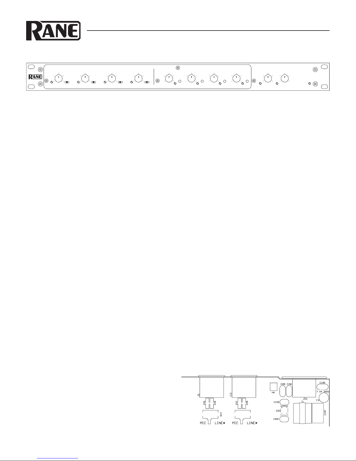
OPERATING INSTRUCTIONS
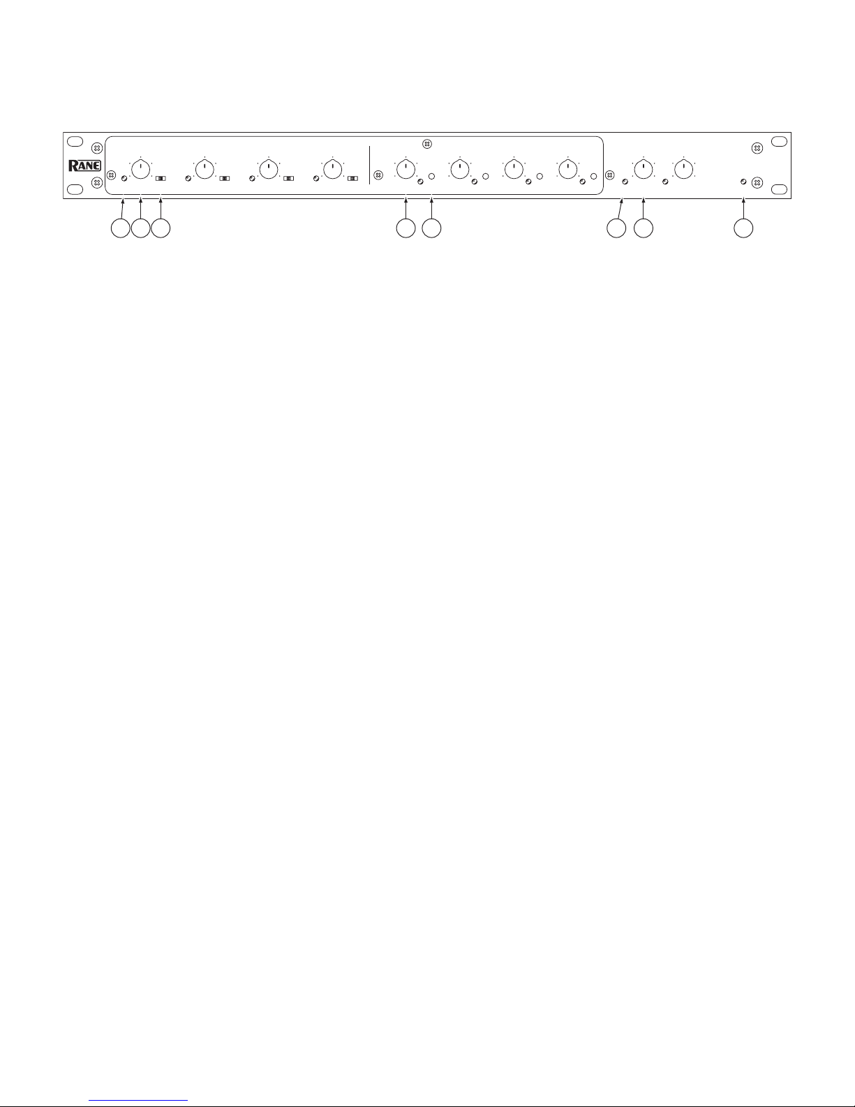
MONO MICROPHONE/LINE LEVEL INPUTS 1-4
e microphone pre-amps in the MLM 82S have a combination
gain trim, Level control. e LEVEL control adjusts both the
input dynamic range and mix level. ere is no need for the typi-
cal independent gain trim control found on most mixers. e
PHANTOM POWER switch activates 15 volt Phantom Power
for all Inputs selected for microphone use. With LINE selected,
Phantom Power is defeated only in that Input. 15 volts is suffi-
cient power for all but the most esoteric condenser microphones.
If in doubt, check the manufacturer’s microphone specs.
SIGNAL PRESENT/OVERLOAD INDICATORS
e MLM 82S has four bi-color indicators for Signal Present/
Overload (green/red). Green indication occurs when there is a
signal present above -30 dBu. is lamp should be glowing green
when signal is present. If this lamp is off, check these possibili-
ties:
A. e Input may not be connected.
B. ere is little or no signal present at the moment.
C. ere is a Mic connected to a channel switched to LINE.
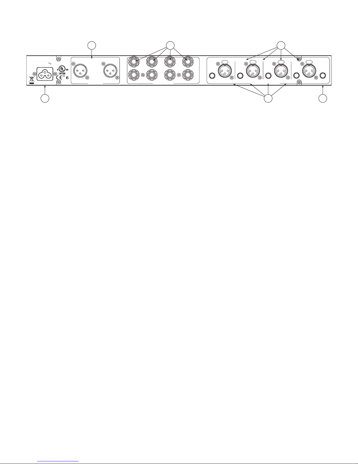
D. e Mic needs Phantom Power (See Rear Panel, 2).
E. e LEVEL control needs to be increased (clockwise).
F. e cable is not wired properly (See the Sound System Inter-
connection RaneNote).
A red glowing LED indicates that the levels are so high that
distortion due to clipping is occurring or imminent.
Check these conditions:
A. e LEVEL control may be turned too high.
B. e Output of the preceding device may need to be reduced.
C. e Input may be switched to MIC with a line-level source.
Switch the Input to LINE.
STEREO LINE INPUTS 5 through 8 do not have overload
indicators. Because 12 dB of gain is added after the STEREO
LINE INPUT LEVEL controls, it is possible to overload a line
input without an overload indication. e A and B OUTPUT
OL indicators can overload from the Line Inputs if the OUT-
PUT LEVEL controls are set to 10. Although a single Input may
be at unity gain, multiple active Inputs mixed together can cause
an overload. If the OL indicators illuminate, just turn down the
OUTPUT LEVELS until the overload stops—mix ratios will
not change.
STEREO LINE LEVEL INPUTS 5-8
e STEREO LINE INPUT LEVEL controls adjust both A and
B Inputs equally. Use the OUTPUT LEVEL controls together
for overall output adjustment, or separately to control balance.
A single mono input may be used for the A and/or B inputs.
Any mono source connected to A will go to the A output. Any
mono source connected to the B input will go to the B output.
If you wish one or two mono sources to go to both A and B
outputs, press the MONO switch. If you wish to mono a single
stereo source and have it present in A and B outputs, press the
mono switch. STEREO LINE INPUTS 5-8 may each be inde-
pendently set for mono operation.
HOLE PLUGS
To protect the setting of any rotary control, remove the knob by
simply pulling it off, and snap in one of the hole plugs included
with your unit.
To protect the entire front panel, use a Rane SC 1.7 Security
Cover.
Other manuals for MLM82S
3
Table of contents
Other Rane Music Mixer manuals