Manual-1
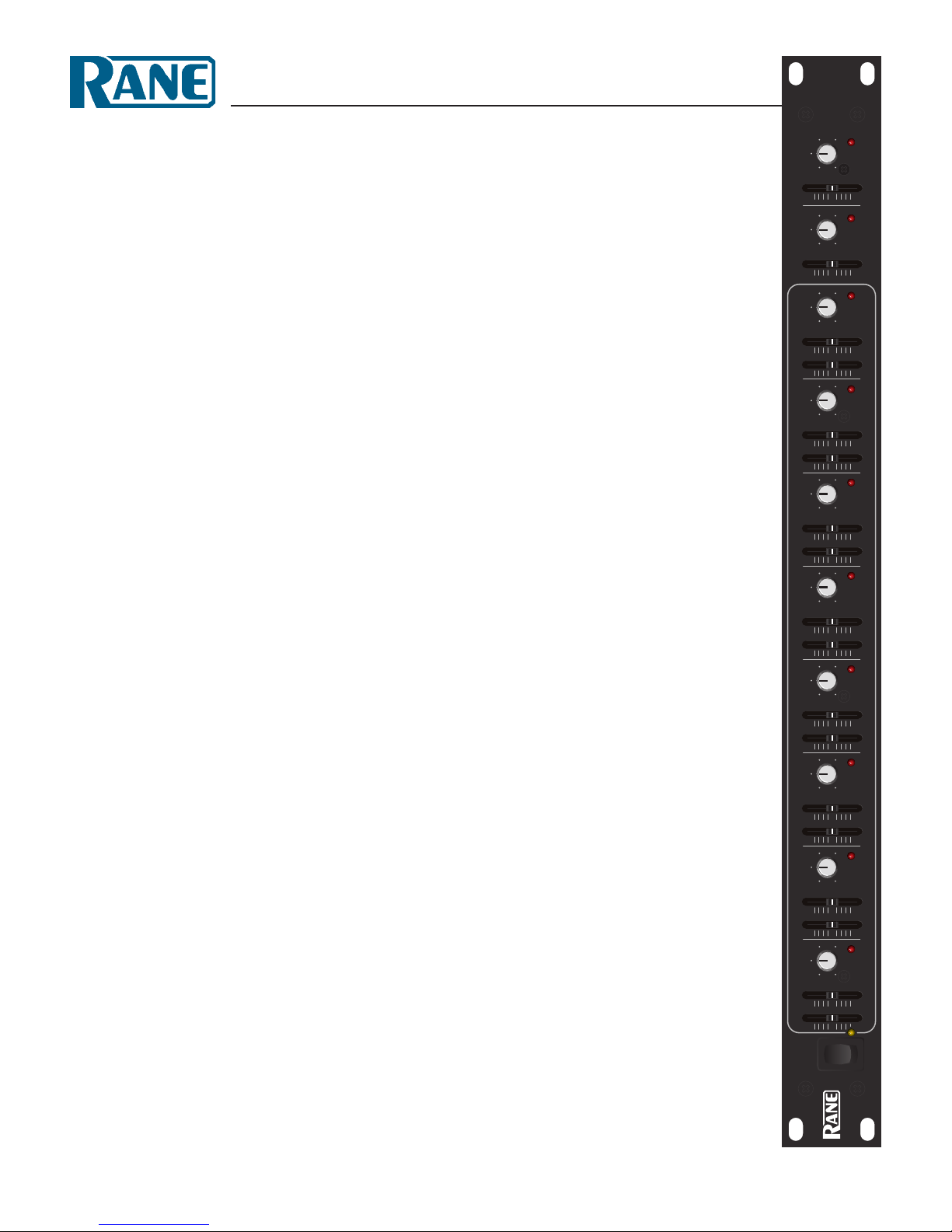
OPERATORS MANUAL SM 82
STEREO MIXER
QUICK START
No one likes to read manuals. Everyone likes to just start pushing buttons and turning knobs until the desired results magically
emerge. at’s usually OK, and with a very few exceptions, damage is unlikely to result from such procedures with the SM 82.
is product is quite obvious: Input LEVEL controls make Inputs louder or not, the stereo SENDs make things happen at the
LOOP SEND outputs, and so on. No real magic there. You should be aware, however, that if you want to connect a mono source to
the SM 82, use only the LEFT Input of a channel so that the mono source will drive both the Left and the Right channels.
Set the levels of the mixer so that the red lights stay off. If they come on, you are overdoing it and distortion will result.
Never connect anything except an RS 1 or other approved Rane AC power supply to the thing that looks like a telephone
jack on the rear of the SM 82. is is an AC input and requires some special attention if you do not have an operational power sup-
ply exactly like the one that was originally packed with your unit. See the full explanation of the power supply requirements on page
Manual-3..
SM 82 CONNECTION
When connecting the SM 82 to other components in your
system for the first time, leave the power supply for last. is will
give you a chance to make mistakes and correct them before any
damage is done to your fragile speakers and ears.
INPUTS
e SM 82’s Inputs are unbalanced. is means that stan-
dard ¼" connectors on the ends of any good quality cable will
work well between your signal sources, signal processing and
amplification. For best rejection of nasty things like hum and
RF, keep input cables under 10 feet (3 meters) in length.
Most sources give you the choice of stereo or mono output.
e mixer gives you the same choice. You will note that nomen-
clature has been placed beneath the input jacks indicating which
is RIGHT and which is LEFT (MONO). If a source is plugged
only into the Left jack and not into the Right, both Right and
Left channels will be fed with the Left Input. is allows the use
of either stereo or mono sources.
OUTPUTS
e SM 82 offers balanced main outputs only. is means
that you may use them as either balanced or unbalanced, the
choice being made by the way the connectors are wired. It’s a
good idea to always use a TRS or stereo connector in the outputs
no matter which mode you are using. If a “mono” connector
is used, inserting it into the output will short the ring (–) to
ground and could conceivably cause a small amount of distortion
to be placed on the tip (+). While this is not destructive, it may
be significant enough to be audible. Balancing therefore requires
that both tip (+) and ring (–) be wired to the following device.
Unbalanced requires only tip and sleeve connected, leaving the
unused ring open.
EFFECTS DEVICES
External devices which might be used could be either mono
in and out, while some may be mono in and stereo out, while
still others may be stereo on both ends. e SM 82 easily ac-
commodates all of these varieties. If your effect is mono on both
ends, connect its input to the SM 82 LEFT LOOP SEND and
the effect’s output to the SM 82 LEFT LOOP RETURN. is
configuration will sum Right and Left Loop Outputs to the
mono effect input and will sum the mono effect output to the
Left and Right Input buses. A mono-in stereo-out device would
connect to the loop outputs in the same way; however the stereo
outputs connect to the respective LEFT and RIGHT LOOP
RETURNS.
EXPANDING
Connecting two or more SM 82s together to achieve more
than eight stereo Inputs requires that a stereo cable (tip, ring,
sleeve) be connected between the MAIN EXPAND OUTPUT
of the first mixer and the MAIN EXPAND INPUT of the
second. All 32 inputs will then appear at the main OUTPUT of
mixer number two. Only the first sixteen Inputs will be available
at the main Outputs of mixer number one. Should you wish to
have all Loop buses tied, connect the LOOP SENDS of mixer
one to the LOOP EXPAND INPUT of mixer two. All sixteen
stereo sends will then become active at the LOOP SENDS of the
second mixer.
WEAR PARTS: is product contains no wear parts.
1 2
SM 82
SEND
BAL
SEND
BAL
3
SEND
BAL
4
SEND
BAL
5
SEND
BAL
6
SEND
BAL
7
SEND
BAL
8RETURN OUTPUT
SEND
BAL BAL BAL
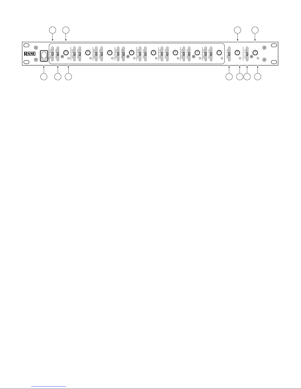
OL OL OL OL OL OL OL OL OL OL
LEVEL LEVELPOWER LEVEL LEVEL LEVEL LEVEL LEVEL LEVEL LEVEL LEVEL
0
2
4
8
6
0
2
4
8
6
0
2
4
8
6
0
2
4
8
6
0
2
4
8
6
0
2
4
8
6
0
2
4
8
6
0
2
4
8
6
0
2
4
8
6
0
2
4
8
6
10 10 10 10 10 10 10 10 10 10
0
5
10
STEREO
MIXER
R
C
L
0
5
10
R
C
L
0
5
10
R
C
L
0
5
10
R
C
L
0
5
10
R
C
L
0
5
10
R
C
L
0
5
10
R
C
L
0
5
10
R
C
L
R
C
L
R
C
L