Rapid-Air SA3 User manual

! !
RAPID-AIR
OPERATING INSTRUCTIONS FOR
RAPID-AIR
4601 KISHWAUKEE ST.
ROCKFORD, IL. 61109-2925
PHONE: (815) 397-2578
FAX: (815) 398-3887
WEB SITE: www.rapidair.com
SA3, SA3M, SB4, SB4M
STOCK STRAIGHTENERS

! !
TABLE OF CONTENTS
1.
PAGE
STRAIGHTENER "HEAD-ONLY" DRAWING
2. INSTALLATION
3. OPERATION
4.
5.
6. KEYPAD FUNCTIONS
7.
TECH. BULLETIN (straightener roll adjustment)
KEYPAD FUNCTIONS
KEYPAD FUNCTIONS
8. JOG SPEED ADJUSTMENT AND DANCER ARM CALIBRATION
9. JOG SPEED ADJUSTMENT AND DANCER ARM CALIBRATION
10. MAINTENANCE
11. TROUBLESHOOTING
12. TROUBLESHOOTING
13. SA3/SA3M CABINET ASSEMBLY DRAWING
14.
15.
16. SA3 HEAD ASSEMBLY DRAWING (sheet 2 of 2)
17.
SB4/SB4M CABINET ASSEMBLY DRAWING
SA3 HEAD ASSEMBLY DRAWING (sheet 1 of 2)
SA3M HEAD ASSEMBLY DRAWING (sheet 1 of 2)
18. SA3M HEAD ASSEMBLY DRAWING (sheet 2 of 2)
19. SB4 HEAD ASSEMBLY DRAWING (sheet 1 of 2)
20. SB4 HEAD ASSEMBLY DRAWING (sheet 2 of 2)
21. SB4M HEAD ASSEMBLY DRAWING (sheet 1 of 2)
22. SB4M HEAD ASSEMBLY DRAWING (sheet 2 of 2)
23. WIRING DIAGRAM

! !
1
(SA3 STRAIGHTENER SHOWN)
PUSHBUTTON
CONTROL
ASSEMBLY
MOTOR
ENTRANCE
GUIDE
ROLLS
DANCER
ARM
ASSEMBLY
PINCH ROLL
ADJUSTING
KNOB
PLATEN
ADJUSTING
KNOBS
C
LSTOCK
ECCENTRIC
ADJUSTMENT
STRAIGHTENER "HEAD-ONLY" DRAWING
SA3
SA3M
SB4
SB4M
MODEL
MAX.
MATERIAL
WIDTH
Effective
Straightening
Range
Max.
Speed
in./min.
AC Input
Power
Required
3"
3"
4"
4"
.002-.030"
(.051-.76mm)
.002-.030"
(.051-.76mm)
.003-.050"
(.076 -1.27mm)
.003-.050"
(.076 -1.27mm)
700"
(1778cm)
1400"
(3556cm)
825"
(2100cm)
1650"
(4200cm)
1/4hp, 115vac, 1ph
1/2hp, 115vac, 1ph
1/2hp, 115vac, 1ph
1/2hp, 115vac, 1ph
TOP
COVER
TOP COVER
LOCKING
KNOB

! !
2
1. Your straightener is fully assembled and ready to be put
into position. Visually inspect unit for damaged or loose
parts due to shipment. If there is physical damage contact
carrier.
2. Install your straightener on a level surface with sufficient
clearance for loading material and adjusting the roller
pressure for straightening. Align and center your unit to
the device that will be supplying the stock. For safe operation,
bolt unit to the floor. Before bolting your unit to the floor, check
for the longest feed length and position your straightener so
that there will be about two or three feed lengths in the storage
loop without re-inducing coil set in the material.
CAUTION - Disconnect electrical power before performing
any service to this machine.
INSTALLATION
3. Before inserting material into your straightener, turn on the main
power button and run a test cycle using the jog button. Also run
a test cycle in the run mode using the dancer arm to test that the
speed varies if using the proportional control. Test all other
electrical features before continuing.
4. Once these tests have been completed and all the functions are
working properly, your straightener can now be used for what it
was designed to do and that is to remove coil set.

! !
3
OPERATION
1. Retract the upper pinch roll and upper idler roll platen to a
position so that when the cover is closed the material is not
being deformed. Open the cover of the straightener and
position the edge guides for the maximum width. Cut and place
about a four foot length of material onto the straightener rolls
with the exit end of the material extending through the exit
pinch rolls and centered from side to side in the straightener.
Close the cover and latch it. Adjust the exit pinch roll enough
to grip and hold the material. Adjust the edge guides so that
they just touch the material.
2. Adjust upper idler roll platen (using platen adjusting knobs) to
remove coil set. Most of the coil set should be removed with
the roller closest to the entrance end of the straightener with
declining adjustment as material passes through the rollers
closest to the exit end of the straightener. Never overwork the
material to the point where opposite coil set is established.
3. Depending on the amount of coil set in your material and the
type of material you are trying to straighten, you may be
required to run the material through the straightener several
times with several adjustments before the required results
are achieved.
4. Refer to the Tech. Bulletin on page 4 in this manual for material
straightening procedures.

! !

! !
5
OFF
EXTERNAL LOOP PLUG
RAPID-AIR EQUIPMENT ONLY
ON RESET
RAPID-AIR
Mode
STOP/
RUN/
JOG
JOG
Arm
Range
LOOP
RANGE
+
LOOP
RANGE
-
LOOP
ARM
EXTER.
Loop
Type
LOOP
HT.
-
%
SPEED
-
Min-0
Max- 8
Min-0
Max- 8
Arm
Height
LOOP
HT.
+
%
SPEED
+
Start
Speed
CAUTION: DISCONNECT ELECTRICAL POWER
BEFORE PREFORMING ANY
SERVICE TO THIS MACHINE.
Operating Instructions
In Stop Mode: Select Loop Arm or External Loop Control.
Position Loop Sensor Above Material Loop.
Set Estimated % Max Speed, Loop Height and Loop Range.
In Run Mode: Adjust % Max Speed, Loop Height and Loop Range for Smooth Operation.
STRAIGHTENER & POWER ROLL
Min-0
Max-100
POWER ROLL KEYPAD
MAIN
POWER
SWITCH
CIRCUIT
BREAKER
% SPEED
STOP/RUN/JOG
MODE
LOOP TYPE
DANCER OR EXTERNAL
LOOP RANGE
LOOP HEIGHT
Prior to applying power to your straightener the operator should
review all controls on this machine. See pages 5-6 in this manual
for a summary of these controls.
KEYPAD FUNCTIONS
REMOTE INTERFACE
PORT "D"

! !
6
Note: Remote interface port "D" connector, if used, communicates
with external loop control.
Warning! - Never plug any type of computer or non Rapid-Air
equipment into this plug or severe damage will result.
Consult factory when installing new external controls.
KEYPAD FUNCTIONS
Run/Stop/Jog
In the Run mode, if the dancer arm is moved the pinch rolls
In the Jog mode, the jog button has to be depressed for the
rolls to turn. Jog function is used mainly for setup.
In the Stop mode there is no movement of the rolls.
On/Off switch
This illuminated switch is the main power switch for the
controller. It must be "ON" for the straightener to function.
Reset switch
This is the main circuit breaker for the straightener.
and lower straightening rolls will turn.
Loop arm/external switch
When using a dancer arm, select loop arm button to display
"LV" for vertical. This button will also allow you to select
"LH" for horizontal. ("LH" is used for Pallet Master decoilers
only)
When using an external loop control, select external loop to
display "RT" for RTB or "RS" for RS2.

! !
7
KEYPAD FUNCTIONS
Loop range/height
The loop range function selects the degree of arm movement
to achieve maximum motor speed. If a loop range of "0" was
selected the the arm would only have to travel approximately
6° to have the straightener at full speed. If a loop range of "8"
was selected the arm would travel approximately 60° to have
the straightener at full speed. This function is active in the
8
7
6
5
4
3
2
10
AT REST
Loop Range
Each number
is the distance
from rest that
the dancer has
to move to
achieve full speed
of the reel motor
8
7
6
5
4
3
2
10
AT REST
Loop Height
Each number
is the distance
from rest that
the dancer has
to move to
start reel rotation
The loop height function selects the degree of arm movement
to start roll rotation. If a loop range of "0" was selected
the the arm would only have to travel approximately 6° to
start roll rotation. If a loop range of "8" was selected the
arm would travel approximately 60° before starting roll
To set the loop height, thread up the material with the dancer arm
resting on the material. If the straightener is running with the
dancer arm in this position adjust the loop height until straightener
stops. This is your new at rest position. This function is active in
% Speed setting
The % speed setting allows you to adjust the maximum speed
the rolls will rotate. This should be set to maintain a constant
feed rate. This function is active in the "RUN" mode.
"RUN" mode.
rotation.
the "RUN" mode.

! !
JOG SPEED ADJUSTMENT & DANCER ARM
CALIBRATION
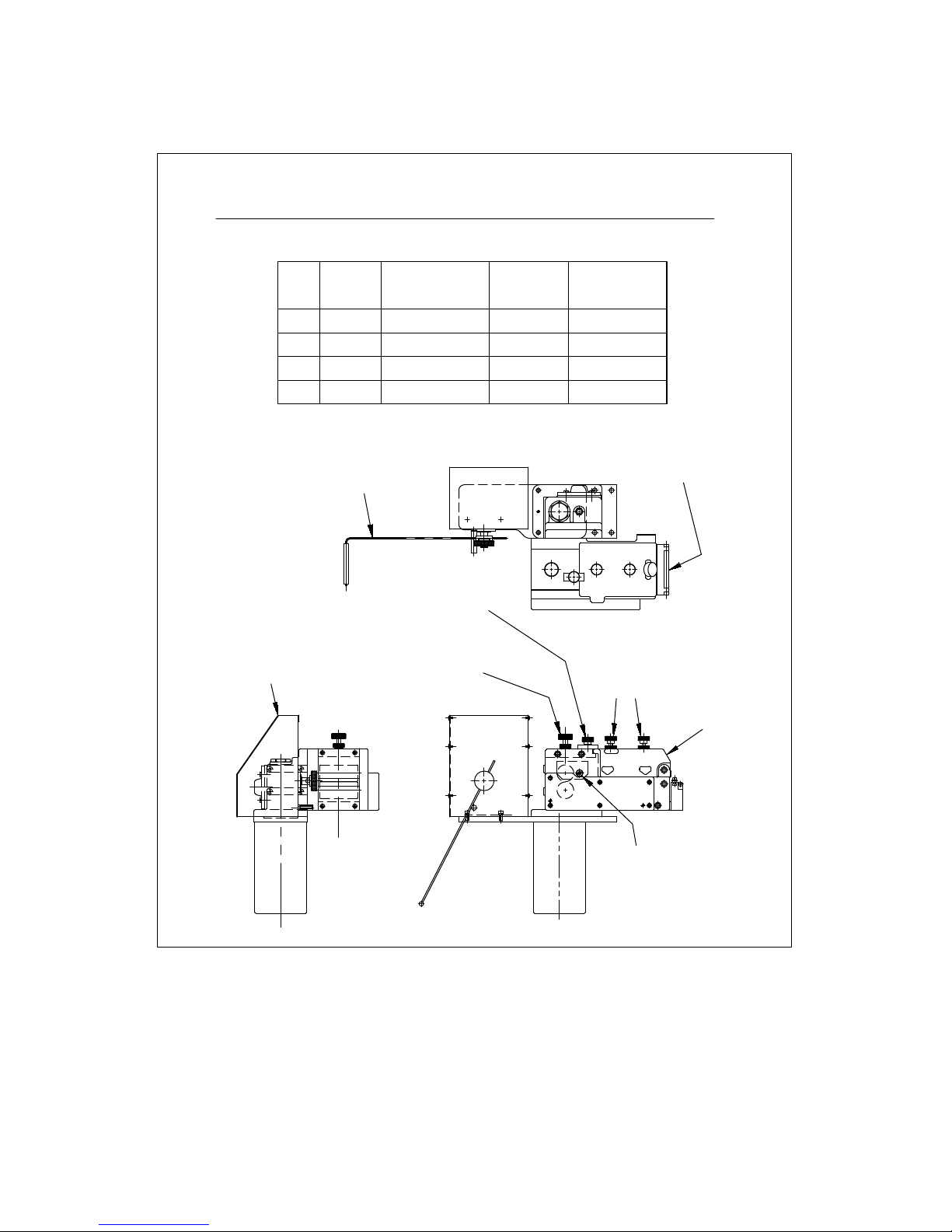
Your straightener was shipped with the dancer arm set up for it's
correct position so the only thing that has to be reset would be
the jog speed if you need your unit to jog faster or slower.
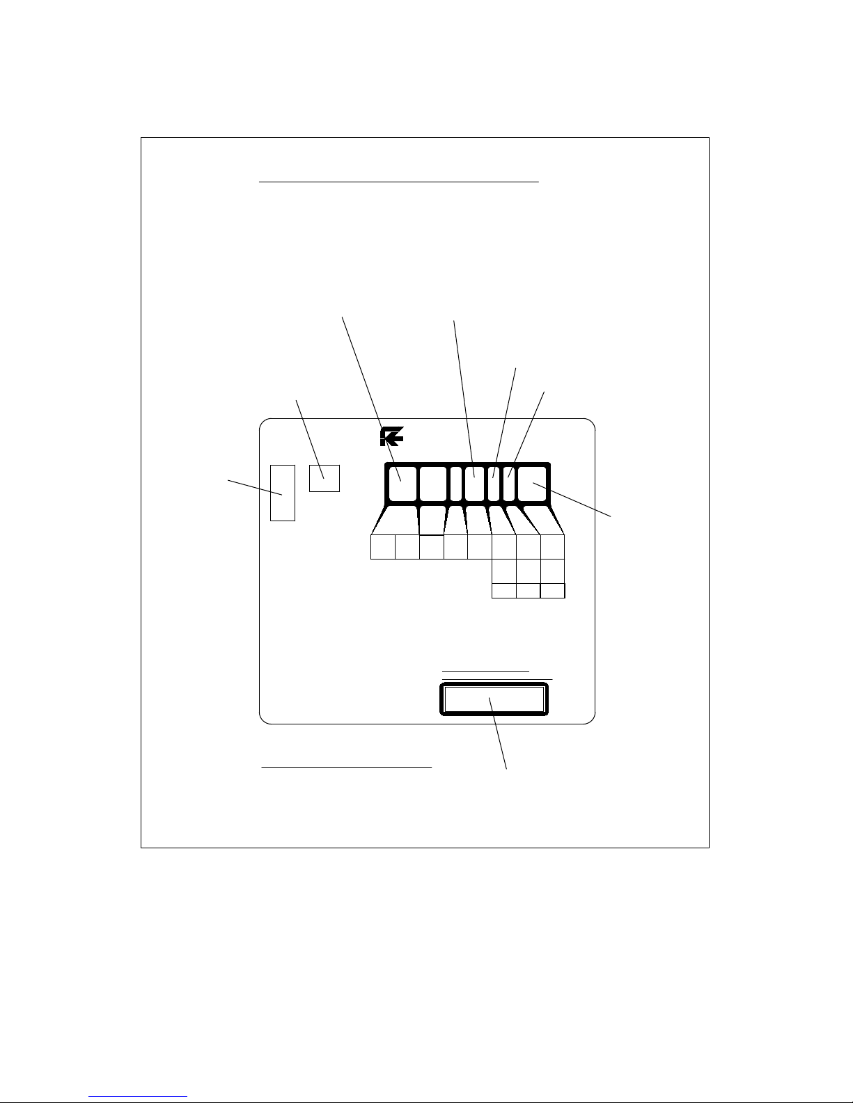
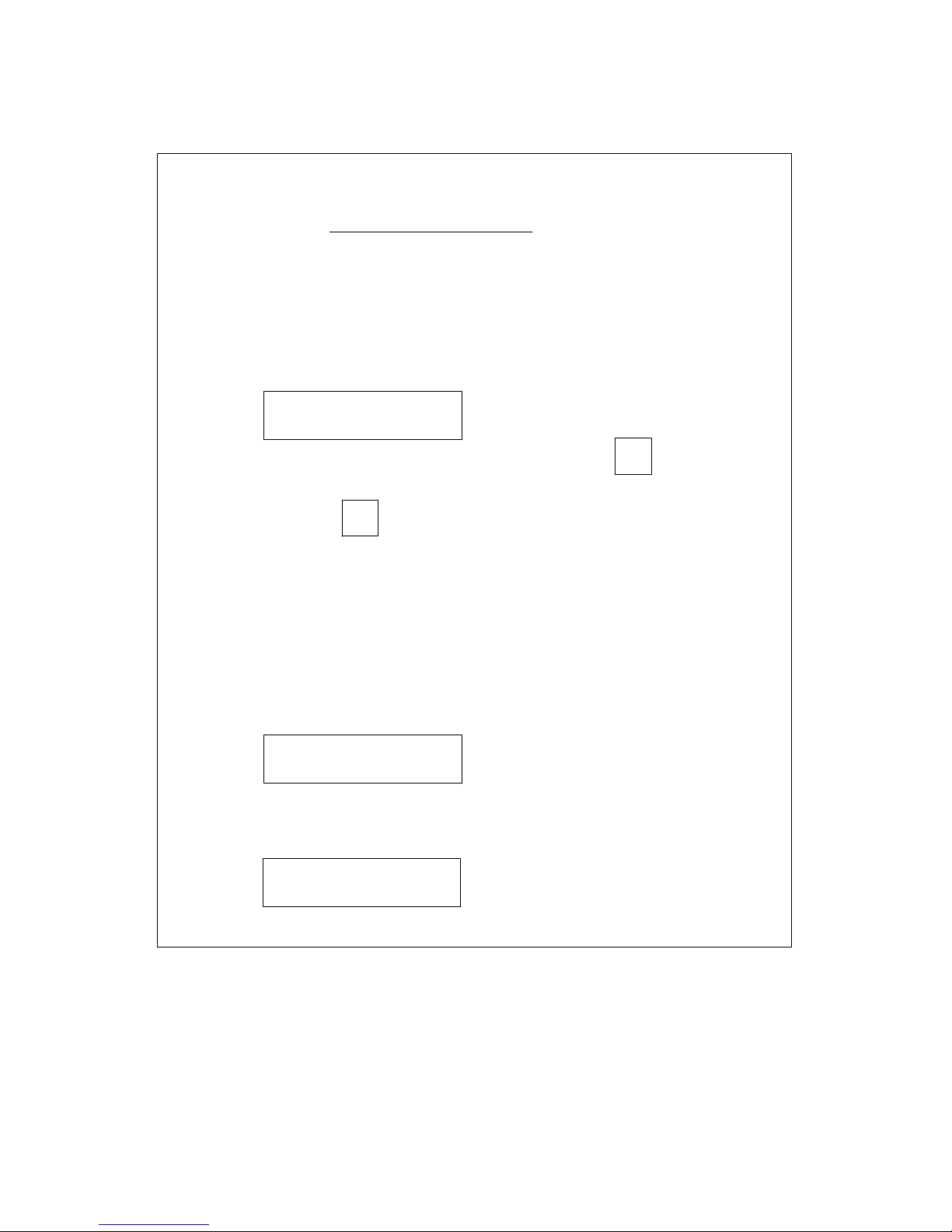
To reset the jog speed, turn off the main power switch. Press and
hold the "Run/Stop/Jog" button while turning the main power switch
on. The first screen you will see will display the jog speed percentage.
SETUP SENSOR
NEXT
To increase the jog speed, press the "Start Speed"
pushbutton. If you want to decrease the jog speed press the
"Start Speed" pushbutton.
%
SPEED
+
%
SPEED
The jog speed is shown in the percent of maximum jog speed.
Once you have set the desired jog speed push the "Run/Stop/Jog"
button once for next. Your jog speed is now set.
The next screen asks if you want to set up the sensor (commonly
referred to as "dancer arm calibration"). Use the percent speed
Select "no" if all you wanted to do was change the jog speed, select
"yes" if you want to calibrate the dancer arm by resetting the sensor.
buttons to select "yes" or "no".
YES
NO
After making your selection, press
"Run/Stop/Jog" for next.
If you selected "yes" the next screen asks you to set the low set point.
If the dancer arm is resting on the positive stop then just save this
setting by pushing the "Run/Stop/Jog" button.
JOG SPEED
NEXT
23% +
_
_
SENSOR LOW SETPOINT
SAVE xxx
8

! !
JOG SPEED ADJUSTMENT & DANCER ARM
CALIBRATION
The next screen is for setting the high set point. Raise the dancer
arm to it's upper stop position and press the "Run/Stop/Jog" button
once to save this setting.
SENSOR HIGH SETPOINT
SAVE xxx
The next screen is to set the offset of the program. Potentiometers
are hard to get set perfectly so we've built in an offset. After setting
the high & low points, with the dancer arm resting on the positive
stop, put the unit in the "Run" mode. If the unit starts running with
the dancer arm on the positive stop then an offset needs to be put
in. If an offset needs to be put in go through the setup procedure
LOW OFFSET
NEXT
+0 +
_
You now have set the dancer arm limits. The next screen to appear
allows you to exit the setup. Use the percent speed button to enter
"yes or no".
EXIT SETUP YES
NO
If "yes" was selected press "Run/Stop/Jog" button and the next screen
SHUT OFF POWER TO
SAVE AND EXIT
again until you get to the low offset screen. Using the percent speed
buttons put in an offset value of -3 to -5. Press the "Run/Stop/Jog"
button to save this setting.
appears.
Power off unit, the dancer arm is now ready for production running.
9

! !
MAINTENANCE
Gearbox lubrication - change oil every 1000 hours as follows:
Electrical - all brushes on motors should be checked every
1500-2000 hours.
10
Your straightener was shipped from the factory with
the upper & lower pinch rolls parallel to each other.
If these pinch rolls should happen to get out of parallel,
use eccentric shaft to adjust rolls. See diagram page 1
for location of eccentric shaft. Loosen socket head cap
screw in center of shaft. Turn shaft until rolls are parallel
with each other. You should be able to grip .001 thick
shim stock along entire width of rollers. After adjustment
is made, re-tighten socket head cap screw.
BREATHER
FILL/
MOTOR
CASE
BREATHER
FILL/
DRAIN
SPUR
GEAR
CASE
OIL
LEVEL
OIL
PLUG
DRAIN
OIL
LEVEL
SA3/SA3M STRAIGHTENER
MOTOR CASE
FILL TO OIL PLUG
APPROX. 4 oz
MOBIL 600 W
SPUR GEAR CASE
NO OIL PLUG OR SIGHT
APPROX. 4 oz.
MOBIL 600W
BREATHER
FILL/
OIL
LEVEL
OIL
PLUG
DRAIN
BREATHER
DRAIN
OIL
LEVEL
FILL/
MOTOR
CASE
SPUR
GEAR
CASE
SB4/SB4M STRAIGHTENER
MOTOR CASE
FILL TO OIL PLUG
APPROX. 4 oz
MOBIL 600 W
SPUR GEAR CASE
NO OIL PLUG OR SIGHT
APPROX. 6 oz.
MOBIL 600W

! !
TROUBLESHOOTING
MAIN SWITCH ON BUT NOT LIT
1. Circuit breaker tripped
a. Reset circuit breaker
2. Unit not plugged into main power
a. Plug into main power
3. No power in incoming line
a. Check outlet
b. Check power cord
4. Loose wiring
a. Check terminals and connections
MOTOR CREEPS IN STOP POSITION
1. "Min." speed pot on RAMM board out of adjustment
2. Offset in dancer arm setup out of adjustment (see page 8)
UNIT ON BUT MOTOR WON'T RUN
(armature voltage present on RAMM board)
1. Check motor wiring
a. replace motor cord or correct motor wiring (consult factory)
2. Check motor
a. Worn brushes or defective motor (consult factory)
b. Check for oil in motor, gear box oil seal may have failed
UNIT ON BUT MOTOR WON'T RUN
(no armature voltage present on RAMM board)
1. Selector switch not in "RUN" position
a. Turn selector switch to "RUN" position
2. If running with a dancer arm control
a. Check that the external/loop arm function is in the
loop arm position
3. If running with external control
a. Check that the external/loop arm function is in the
external position
4. Loop height switch setting to high
a. Set height setting to "0"
11

! !
TROUBLESHOOTING
5. Percent speed function set too low
a. Adjust percent speed function to 100%
6. Fuses blown
a. Check fuses & circuit breaker
7. No AC voltage at DC drive board
a. Check wiring
8. Check signal voltage between P2 to P1 on DC drive
0-6 VDC - RAMM
0-9 VDC - Regen drive
while moving dancer arm
a. If there is a signal, check continuity between I1 & I2
If no continuity, replace DC drive or consult factory
9. Check pico fuse on 69100804 board (F1)
a. Replace fuse,1 amp pico fuse-consult factory
69100804 Board
69100014
Board
29100021
Potentiometer
12

! !
13
RAPIDAIR
40.5"
PASS LINE
20"
28"
SA3/SA3M CABINET ASSEMBLY

! !
14
RAPIDAIR
RAPID AIR CORP.
CAUTION
MODEL
SERIAL
UP
CURVE
DN
SB4/SB4M CABINET ASSEMBLY
40.5"
PASS LINE
28"
20"

! !
15
FRACTIONS
DECIMALS
DRAWING NUMBER
WEIGHT
HARDNESS
FINAL FINISHCHECKED BY
SCALE
DATE
DRAWN BY
HEAT TREAT
MATERIAL
PART NAME
63
FINISH
1/64
.0005
.005
.010
.030
.0000
.000
.00
.0
FOUR PLACE
THREE PLACE
TWO PLACE
ONE PLACE
UNLESS OTHERWISE SPECIFIED
STANDARD MFG. TOLERANCES
ASS'Y.
NEXT
REV. CHANGE DATE FULL E
AA
SECTION
AA
10
20
71
(4)
(2)
26 87 147 95
(2)
145
(2) (2)
B
B
SECTION
BB
C
C
SECTION
CC
74
29 15 52 93
63
102
85
16 62
139
103
62
89
88
85
83
34
108
93
(2)
64
85
34
108
93
(1)
103
77
84
1
2
75 139
140
22 72
90
108
32
63
21
64
33
132
93
42
123
13
43
34
108
93
3 4
12
11
124
92
146
139
35
64
91
36
109
146
139
75
(1) (2) 64
86
23
150
129
118
119
151
126 137
128 148
REF. 31700530 NO CONTROL
126
137
135
137
D
D
VIEW
DD
REF. 31701995 WITH CONTROL
MOUNTING PLATE
27 78
80
INNER SPRING
OUTER SPRING
124
51
19 65 73
97
73
65
65
65
100
28
99
97
41
126
121
39
125
SA3 STRAIGHTENER
SHEET 1 OF 2
(1) (1)
102 (1)
102 (1)
NOTE: ITEM #26 ROLLER TO BE PACKED
FULL LENGTH WITH BEARING
LUBRICANT
(1) (1)
(2)
(1)
(1)
(1)
(4)
(1)
(1)
(1)
(2) (2)
(2)
(2)
(2)
(1)
(1)
(1)
(1)
(3)
118 (1)
149
127
(6)
102
(2)
131
(4)
(1) (2)
(1)
(1)
(1)
(1)
(1)
(1)
122
9
14
8
120
102
(4)
(1)
(1)
(1)
(1)
(1)
(1)
(1)
(1)
(4)
(1)
(1)
(1)
(1)
102
(1)
(1)
104 ROLL
PIN
5
6
USE LOCTITE
518 GASKET
ELIMINATOR
USE LOCTITE
518 GASKET
ELIMINATOR
5-26-2015
W/ONE-PIECE ROLLER)
DLU
26400229
11200573
(1)
A ECN #5562
9/22/16
B
B ECN #5673
11/14/17
SA3 HEAD ASSEMBLY DRAWING
(sheet 1 of 2)

! !
16
FRACTIONS
DECIMALS
DRAWING NUMBER
WEIGHT
HARDNESS
FINAL FINISHCHECKED BY
SCALE
DATE
DRAWN BY
HEAT TREAT
MATERIAL
PART NAME
63
FINISH
1/64
.0005
.005
.010
.030
.0000
.000
.00
.0
FOUR PLACE
THREE PLACE
TWO PLACE
ONE PLACE
UNLESS OTHERWISE SPECIFIED
STANDARD MFG. TOLERANCES
ASS'Y.
NEXT
REV. CHANGE DATE FULL E
56
58
73
112
114
61
105
141
48
81
115
49
124
50
124
(2)
(2)
79
127
59
60
134
57
141
113
61
105
111
141 76
136
GEAR ROLLOUT
DESCRIPTIONPART NO.QTY.ITEM
1
2
3
4
5
6
7
8
9
10
11
12
13
14
15
DESCRIPTIONPART NO.QTY.ITEM
16
17
18
19
20
21
22
1 30100057 GEAR HOUSING
1 31500111 WORM COVER
1 30100053 CONTROL SIDE FRAME
1 30100054 DRIVE SIDE FRAME
1 31500123 ROLLER SUPPORT COVER
1 31500124 GEAR CASE COVER
1 31900406 IDLER BRACKET
1 31900407 SQUEEZE BRACKET
1 31900408 SQUEEZE BRACKET
1 31900429 GUIDE SUPPORT BRACKET
1 31900428 GUIDE
1 34100120 LOWER SPACER
1 34100121 UPPER SPACER
1 34100119 SQUEEZE SPACER
1 34200447 LOWER PINCH ROLL
1 34200448 UPPER PINCH ROLL
6 32900279 IDLER SHAFT
1 32900280 IDLER SHAFT
1 32900283 GUIDE SHAFT
7 32900284 ROLLER SHAFT
1 32900226 IDLER SHAFT
1 32900228 WORM GEAR SHAFT
23
24
25
26
27
28
29
30
31
99
(13)
(11)
138 (5)
138
(5)
70 (5)
CLOSED
END
25
110
67 (5)
96 (11)
68 (6)
CLOSED
END
67
(6)
138 (11)
65
(1)
73
97
(1)
18 66
30
SEE
SECTION
CC
45
26
20
(6)
(6)
95 (12)
71
(24)
87
(12)
147
(12)
46
94
143
37
125 (2)
47
142
55
106
329002291 WORM SHAFT
5 34200060 LOWER DRIVE ROLLER
31
32
33
34
35
36
37
38
39
40
7 34200061 ROLLER
SA3 STRAIGHTENER
DLU
5-26-2015 26400229
SHEET 2 OF 2
41
42
43
44
45
46
47
48
49
50
1 32600090 RACK
1 32600089 PINNION
1 32600088 SPUR GEAR
11 32600086 SPUR GEAR
1 32600087 SPUR GEAR
1 32600071 WORM GEAR
51
52
53
54
55
56
57
58
59
60
61
62
63
1 32600035 IDLER GEAR
3 32600034 GEAR
1 32600012 WORM
1 36100024 WORM COVER
2 32900286 PIVOT PIN
1 32900287 PIVOT PIN
1 32900288 PIVOT PIN
PIVOT PIN1 32900289
1 32900290 HINGE PIN
1 32900227 PIVOT PIN
1 32900285 ECCENTRIC TRUNION
1 31900410 UPPER LINK
2 31900409 LINK
1 31900411 HORIZ. ADJ. TEE
1 31900412 PIVOT BLOCK
1 31900413 CLAMP BAR
1 31900414 TOP SPRING ANCHOR
1 31900415 BOTTOM SPRING ANCHOR
1 31500125 COVER
1 31500126 UPPER GUARD
1 31500127 LOWER GUARD
54
53
130
1 36700015 KNOB
1 66700041 THUMB SCREW
2 36200018 LOCK NUT
1 65230004 LOCK NUT
2 36200005 NUT
2 34200005 ROLLER
3 36700017 KNOB
2 64500032 NEEDLE BEARING
2 64500002 NEEDLE BEARING
64
65
66
67
68
69
70
71
72
73
74
75
76
77
78
79
80
81
82
83
84
85
86
87
88
89
90
91
92
93
94
95
96
97
98
99
100
101
102
103
104
105
106
107
108
109
110
111
112
113
114
115
116
117
118
119
120
121
122
123
124
125
126
4 64500003 NEEDLE BEARING
5 64500028 NEEDLE BEARING
1 64500029 NEEDLE BEARING
11 64500030 NEEDLE BEARING
6 64500034 NEEDLE BEARING
5 64500036 NEEDLE BEARING
28 64500033 NEEDLE BEARING
1 64500031 NEEDLE BEARING
4 64520010 THRUST WASHER
2 64520008 THRUST BEARING
2 64510002 THRUST BEARING
2 37500040 SPRING
2 37500041 SPRING
2 37500042 SPRING
2 37500043
2 37500044
SPRING
SPRING
2 37500045 SPRING
1 37500012 SPRING
1 37500026 WAVE SPRING
1 37500046 FLAT SPRING
3 60200043 SEAL
1 60200072 SEAL
14 37600062 SEAL
1 31800024 SEAL PLATE
1 60108024 "O" RING
1 60108146 "O" RING
1 60108916 "O" RING
1 60810062 SPIRAL RING
98
125(2)
40 96
(2)
44 101
DESCRIPTIONPART NO.QTY.ITEM
127
6 60910062 RETAINING RING
1 60910031
14 60910015
13 60910025
4 60910037
RETAINING RING
RETAINING RING
RETAINING RING
RETAINING RING
2 33600168 INDICATOR PIN
13 62312025 DOWEL PIN
1 62312062 DOWEL PIN
2 62325100 DOWEL PIN
10 62325075 DOWEL PIN
2 62325150 DOWEL PIN
1 62409050 ROLL PIN
3 62412062 ROLL PIN
1 62412125 ROLL PIN
4 36800005 KEY
1 36800010 KEY
5 60200049 SEAL
3 65600002 INSERT
1 65600004 INSERT
1 33700014 ADJ. STUD
1 33700015 ADJ. STUD
1 33700016 ADJ. STUD
2 63130125 PIPE PLUG
1 63130375 PIPE PLUG
5 65936475 SHCS 3/8-16 X 4 3/4
1 66536100 FHSCS 3/8-16 X 1
1 65912200 SHCS #10-32 X 2
1 65912087 SHCS #10-32 X 7/8
12 65912037 SHCS #10-32 X 3/8
5 66212025 SET SCREW
7 65936125 SHCS 3/8-16 X 1 1/4
128
129
130
131
132
133
134
135
136
137
138
8 65920125 SHCS 1/4-20 X 1 1/4
4 65920075 SHCS 1/4-20 X 3/4
4 66612037 BHSCS #10-32 X 3/8
4 65820062 HEX BOLT 1/4-20 X 5/8
1 36100044 HORIZ. ADJ. SCREW
139
140
141
142
143
144
145
146
147
148
2 35900007 STOCK GUIDE SCREW
2 65936175 SHCS 3/8-16 X 1 3/4
2 61300010 WASHER
6 61300037 WASHER
21 34700057 WASHER
9 64520002 WASHER
1 64520005 WASHER
3 34700062 WASHER
149
150
151
152
153
155
156
157
154
1 34700060 WASHER
1 34700061 WASHER
14 34700048 WASHER
2 34100003 SPACER
14 35800051 SEAL RETAINER
1 37901000 OLDHAM COUPLING
1 39900092 INSTRUCTION LABEL
1 39900091 LABEL
1 69420010 BREATHER
1 69420011 BREATHER
1 34700034 WASHER
1 62319025 DOWEL PIN
145
(12)
NOTE: ITEM #26 ROLLER TO BE PACKED
FULL LENGTH WITH BEARING
LUBRICANT
(2)
133
111
(2)
82
7
38
17
(1)
(5)
W/ONE-PIECE ROLLERS
11200573
A
A
A
A ECN #5562
9/22/16
B ECN #5673
11/14/17
B
(sheet 2 of 2)
SA3 HEAD ASSEMBLY DRAWING

! !
17
FRACTIONS
DECIMALS
DRAWING NUMBER
WEIGHT
HARDNESS
FINAL FINISHCHECKED BY
SCALE
DATE
DRAWN BY
HEAT TREAT
MATERIAL
PART NAME
63
FINISH
1/64
.0005
.005
.010
.030
.0000
.000
.00
.0
FOUR PLACE
THREE PLACE
TWO PLACE
ONE PLACE
UNLESS OTHERWISE SPECIFIED
STANDARD MFG. TOLERANCES
ASS'Y.
NEXT
REV. CHANGE DATE FULL E
AA
SECTION
AA
10
20
71
(4)
(2)
26 87 147 95
(2)
145
(2) (2)
B
B
SECTION
BB
C
C
SECTION
CC
74
29 15 52 93
63
102
85
16 62
139
103
62
89
88
85
83
34
108
93
(2)
64
85
34
108
93
(1)
103
77
84
1
2
75 139
140
22 72
90
108
32
63
21
64
33
132
93
42
123
13
43
34
108
93
3 4
12
11
124
92
146
139
35
64
91
36
109
146
139
75
(1) (2) 6486
23
150
129
118
119
151
126 137
128 148
REF. 31700530 NO CONTROL
126
137
135
137
D
D
VIEW
DD
REF. 31701995 WITH CONTROL
MOUNTING PLATE
27 78
80
INNER SPRING
OUTER SPRING
124
51
19 65 73
97
73
65
65
65
100
28
99
97
41
126
121
39
125
SAM3 STRAIGHTENER
SHEET 1 OF 2
(1) (1)
102 (1)
102 (1)
NOTE: ITEM #26 ROLLER TO BE PACKED
FULL LENGTH WITH BEARING
LUBRICANT
(1) (1)
(2)
(1)
(1)
(1)
(4)
(1)
(1)
(1)
(2) (2)
(2)
(2)
(2)
(1)
(1)
(1)
(1)
(3)
118 (1)
149
127
(6)
102
(2)
131
(4)
(1) (2)
(1)
(1)
(1)
(1)
(1)
(1)
122
9
14
8
120
102(4)
(1)
(1)
(1)
(1)
(1)
(1)
(1)
(1)
(4)
(1)
(1)
(1)
(1)
102
(1)
(1)
104 ROLL
PIN
5
6
USE LOCTITE
518 GASKET
ELIMINATOR
USE LOCTITE
518 GASKET
ELIMINATOR
5-26-2015
W/ONE-PIECE ROLLER)
DLU
26400230
11200574
(1)
A ECN #5562
9/22/16
B
B ECN #5673
11/14/17
SA3M HEAD ASSEMBLY DRAWING
(sheet 1 of 2)

! !
18
FRACTIONS
DECIMALS
DRAWING NUMBER
WEIGHT
HARDNESS
FINAL FINISHCHECKED BY
SCALE
DATE
DRAWN BY
HEAT TREAT
MATERIAL
PART NAME
63
FINISH
1/64
.0005
.005
.010
.030
.0000
.000
.00
.0
FOUR PLACE
THREE PLACE
TWO PLACE
ONE PLACE
UNLESS OTHERWISE SPECIFIED
STANDARD MFG. TOLERANCES
ASS'Y.
NEXT
REV. CHANGE DATE FULL E
56
58
73
112
114
61
105
141
48
81
115
49
124
50
124
(2)
(2)
79
127
59
60
134
57
141
113
61
105
111
141 76
136
GEAR ROLLOUT
DESCRIPTIONPART NO.QTY.ITEM
1
2
3
4
5
6
7
8
9
10
11
12
13
14
15
DESCRIPTIONPART NO.QTY.ITEM
16
17
18
19
20
21
22
1 30100057 GEAR HOUSING
1 31500111 WORM COVER
1 30100053 CONTROL SIDE FRAME
1 30100054 DRIVE SIDE FRAME
1 31500123 ROLLER SUPPORT COVER
1 31500124 GEAR CASE COVER
1 31900406 IDLER BRACKET
1 31900407 SQUEEZE BRACKET
1 31900408 SQUEEZE BRACKET
1 31900429 GUIDE SUPPORT BRACKET
1 31900428 GUIDE
1 34100120 LOWER SPACER
1 34100121 UPPER SPACER
1 34100119 SQUEEZE SPACER
1 34200447 LOWER PINCH ROLL
1 34200448 UPPER PINCH ROLL
6 32900279 IDLER SHAFT
1 32900280 IDLER SHAFT
1 32900283 GUIDE SHAFT
7 32900284 ROLLER SHAFT
1 32900226 IDLER SHAFT
1 32900228 WORM GEAR SHAFT
23
24
25
26
27
28
29
30
31
99
(13)
(11)
138 (5)
138
(5)
70 (5)
CLOSED
END
25
110
67 (5)
96 (11)
68 (6)
CLOSED
END
67
(6)
138 (11)
65
(1)
73
(1)
97
(1)
18 66
30
SEE
SECTION
CC
45
26
20
(6)
(6)
95 (12)
71
(24)
87
(12)
147
(12)
46
94
143
37
125 (2)
47
142
55
106
329002291 WORM SHAFT
5 34200060 LOWER DRIVE ROLLER
31
32
33
34
35
36
37
38
39
40
7 34200061 ROLLER
SAM3 STRAIGHTENER
DLU
5-26-2015 26400230
SHEET 2 OF 2
41
42
43
44
45
46
47
48
49
50
1 32600090 RACK
1 32600089 PINNION
1 32600088 SPUR GEAR
11 32600086 SPUR GEAR
1 32600087 SPUR GEAR
1 32600085 WORM GEAR
51
52
53
54
55
56
57
58
59
60
61
62
63
1 32600035 IDLER GEAR
3 32600034 GEAR
1 32600020 WORM
1 36100024 WORM COVER
2 32900286 PIVOT PIN
1 32900287 PIVOT PIN
1 32900288 PIVOT PIN
PIVOT PIN1 32900289
1 32900290 HINGE PIN
1 32900227 PIVOT PIN
1 32900285 ECCENTRIC TRUNION
1 31900410 UPPER LINK
2 31900409 LINK
1 31900411 HORIZ. ADJ. TEE
1 31900412 PIVOT BLOCK
1 31900413 CLAMP BAR
1 31900414 TOP SPRING ANCHOR
1 31900415 BOTTOM SPRING ANCHOR
1 31500125 COVER
1 31500126 UPPER GUARD
1 31500127 LOWER GUARD
54
53
130
1 36700015 KNOB
1 66700041 THUMB SCREW
2 36200018 LOCK NUT
1 65230004 LOCK NUT
2 36200005 NUT
2 34200005 ROLLER
3 36700017 KNOB
2 64500032 NEEDLE BEARING
2 64500002 NEEDLE BEARING
64
65
66
67
68
69
70
71
72
73
74
75
76
77
78
79
80
81
82
83
84
85
86
87
88
89
90
91
92
93
94
95
96
97
98
99
100
101
102
103
104
105
106
107
108
109
110
111
112
113
114
115
116
117
118
119
120
121
122
123
124
125
126
4 64500003 NEEDLE BEARING
5 64500028 NEEDLE BEARING
1 64500029 NEEDLE BEARING
11 64500030 NEEDLE BEARING
6 64500034 NEEDLE BEARING
5 64500036 NEEDLE BEARING
28 64500033 NEEDLE BEARING
1 64500031 NEEDLE BEARING
4 64520010 THRUST WASHER
2 64520008 THRUST BEARING
2 64510002 THRUST BEARING
2 37500040 SPRING
2 37500041 SPRING
2 37500042 SPRING
2 37500043
2 37500044
SPRING
SPRING
2 37500045 SPRING
1 37500012 SPRING
1 37500026 WAVE SPRING
1 37500046 FLAT SPRING
3 60200043 SEAL
1 60200072 SEAL
14 37600062 SEAL
1 31800024 SEAL PLATE
1 60108024 "O" RING
1 60108146 "O" RING
1 60108916 "O" RING
1 60810062 SPIRAL RING
98
125(2)
40 96
(2)
44 101
DESCRIPTIONPART NO.QTY.ITEM
127
6 60910062 RETAINING RING
1 60910031
14 60910015
13 60910025
4 60910037
RETAINING RING
RETAINING RING
RETAINING RING
RETAINING RING
2 33600168 INDICATOR PIN
13 62312025 DOWEL PIN
1 62312062 DOWEL PIN
2 62325100 DOWEL PIN
10 62325075 DOWEL PIN
2 62325150 DOWEL PIN
1 62409050 ROLL PIN
3 62412062 ROLL PIN
1 62412125 ROLL PIN
4 36800005 KEY
1 36800010 KEY
5 60200049 SEAL
3 65600002 INSERT
1 65600004 INSERT
1 33700014 ADJ. STUD
1 33700015 ADJ. STUD
1 33700016 ADJ. STUD
2 63130125 PIPE PLUG
1 63130375 PIPE PLUG
5 65936475 SHCS 3/8-16 X 4 3/4
1 66536100 FHSCS 3/8-16 X 1
1 65912200 SHCS #10-32 X 2
1 65912087 SHCS #10-32 X 7/8
12 65912037 SHCS #10-32 X 3/8
5 66212025 SET SCREW
7 65936125 SHCS 3/8-16 X 1 1/4
128
129
130
131
132
133
134
135
136
137
138
8 65920125 SHCS 1/4-20 X 1 1/4
4 65920075 SHCS 1/4-20 X 3/4
4 66612037 BHSCS #10-32 X 3/8
4 65820062 HEX BOLT 1/4-20 X 5/8
1 36100044 HORIZ. ADJ. SCREW
139
140
141
142
143
144
145
146
147
148
2 35900007 STOCK GUIDE SCREW
2 65936175 SHCS 3/8-16 X 1 3/4
2 61300010 WASHER
6 61300037 WASHER
21 34700057 WASHER
9 64520002 WASHER
1 64520005 WASHER
3 34700062 WASHER
149
150
151
152
153
155
156
157
154
1 34700060 WASHER
1 34700061 WASHER
14 34700048 WASHER
2 34100003 SPACER
14 35800051 SEAL RETAINER
1 37901000 OLDHAM COUPLING
1 39900092 INSTRUCTION LABEL
1 39900091 LABEL
1 69420010 BREATHER
1 69420011 BREATHER
1 34700034 WASHER
1 62319025 DOWEL PIN
145
(12)
NOTE: ITEM #26 ROLLER TO BE PACKED
FULL LENGTH WITH BEARING
LUBRICANT
(2)
133
111
(2)
82
7
38
17
(1)
(5)
W/ONE-PIECE ROLLERS
11200574
A
A ECN #5562
9/22/16
A
A
B
ECN #5673
11/14/17
B
SA3M HEAD ASSEMBLY DRAWING
(sheet 2 of 2)
This manual suits for next models
3
Table of contents