RASHA PROFESSIONAL Blade Owner's manual

QUICK USER MANUAL
RASHA PROFESSIONAL A/S
Rasha Professional A/S | 1800 Rustin Ave, Riverside, CA, 92507 | 951-654-3585
Rashaprofessional.com | info@rashaprofessional.com 1
Blade / Terra

2
Rasha Professional A/S | 1800 Rustin Ave, Riverside, CA, 92507 | 951-654-3585
Rashaprofessional.com | info@rashaprofessional.com
How to turn the controller line from 3-pins into 5-pins (plug and sockets)
Terminator

Keep this device away from dust and extreme temperatures. Make
sure the ventilation openings are clear at all times. For sufficient air
circulation, leave at least 1" (
± 2.5 cm) in front of the openings.
Protect this device from shocks and abuse. Avoid brute force when
operating the device.
3
Rasha Professional A/S | 1800 Rustin Ave, Riverside, CA, 92507 | 951-654-3585
Rashaprofessional.com | info@rashaprofessional.com
1. Introduction
Important environmental information about this product
This symbol on the device or the package indicates that disposal of the device
after its lifecycle could harm the environment. Do not dispose of the unit (or
batteries) as unsorted municipal waste; it should be taken to a specialized
company for recycling. This device should be returned to your distributor or to a local
recycling service. Respect the local environmental rules.
If in doubt, contact your local waste disposal authorities.
Thank you for choosing this product! Please read the manual thoroughly before
bringing this device into service. If the device was damaged in transit, don't install or
use it and contact your dealer.
2. Safety Instructions
3. General Guidelines
Refer to the Service and Quality Warranty
Keep this device away from children and unauthorized users.
Risk of electroshock
when opening the cover. Touching live wires can cause
life
-threatening electroshock. Do not disassemble or open the housing
yourself. Have the device repaired by qualified personnel.
There are no user
-serviceable parts inside the device. Refer to an authorized
dealer for service and/or spare parts.
Do not stare directly at the light source
, as this may cause
epileptic seizure in sensitive people
temporarily loss of sight (flash blindness)
permanent (irreversible) eye damage.
Have the device installed/repaired by a qualified person.

▪Familiarizes yourself with the functions of the device before actually using it.
▪All modifications of the device are forbidden for safety reasons. Damage caused by user
modifications to the device is not covered by the warranty.
▪Only use the device for its intended purpose. Using the device in an unauthorized way will
void the warranty.
▪Damage caused by disregard of certain guidelines in this manual is not covered by the
warranty and the dealer will not accept responsibility for any ensuing defects or problems.
▪Due to constant product improvements, the actual product appearance might differ from
the shown images. Product image
▪Keep this manual for Features are for illustrative purposes only.
▪Do not switch the device on immediately after it has been exposed to changes in
temperature. Protect the device against damage by leaving it switched off until it has
reached room temperature.
4
Rasha Professional A/S | 1800 Rustin Ave, Riverside, CA, 92507 | 951-654-3585
Rashaprofessional.com | info@rashaprofessional.com
4. Overview
4.1 Controller –Technical Specifications
Product Overview
Product Dimensions: Controller

5
Rasha Professional A/S | 1800 Rustin Ave, Riverside, CA, 92507 | 951-654-3585
Rashaprofessional.com | info@rashaprofessional.com
4.2 Setup
AC Power
The pixel controller has an auto-ranging power supply and it can work with an input voltage
range of 100 to 240 VAC, 50/60 Hz.To determine the product’s power requirements (circuit
breaker, power outlet, and wiring), use the current value listed on the label affixed to the
product’s back panel, or refer to the product’s specifications chart. The listed current rating
indicates the product’s average current draw under normal conditions.
▪Always connect the product to a protected circuit (circuit breaker or fuse).
Make sure the product has an appropriate electrical ground to avoid the risk
of electrocution or fire.
▪To eliminate unnecessary wear and improve its lifespan, during periods of
non-use completely disconnect the product from power via breaker or by
unplugging it.
Never connect the product to a rheostat (variable resistor) or dimmer circuit, even if the
rheostat or dimmer channel serves only as a 0 to 100% switch
Fuse Replacement
▪Wedge the tip of a screwdriver into the slot of the fuse holder.
▪Pry the fuse holder out of the housing.
▪Remove the blown fuse from the holder and replace with a fuse of the exact same type
and rating.
▪Insert the fuse holder back in place and reconnect power
Installed fuse
(held by plastic clip)
Disconnect the product from the power outlet before replacing the fuse.

6
Rasha Professional A/S | 1800 Rustin Ave, Riverside, CA, 92507 | 951-654-3585
Rashaprofessional.com | info@rashaprofessional.com
Power Linking
Before mounting the product, read and follow the safety recommendations indicated in the
Safety Notes.
The Blade controller may be mounted in any position; however, make sure adequate
ventilation is provided around the product.
Rigging
•Make sure that the structure onto which you are mounting the product can support
the product’s weight. See the Technical Specifications for weight information.
•When mounting the product overhead, always use a safety cable. Mount the product
securely to a rigging point, whether an elevated platform or a truss.
•When rigging the product onto a truss, use a mounting clamp of appropriate weight
capacity.
•When power linking multiple products, mount the products close enough for power
linking cables to reach.
The product provides power linking via the outlet located in the back of the product.
Please see the diagram below for further explanation.
Power Linking Diagram
Mounting
Controller
The Controller is IP20 rated. Keep it away from water, solvents and chemicals.
Take care to site it away from potential water hazards, for example, avoid
installing it where excessive humidity, water splatter or condensation may
occur
Orientation
Mounting Diagram
Blade Controller(Terra)
Rear Keyhole Mounting
Use a level to ensure accuracy
while mounting

7
Rasha Professional A/S | 1800 Rustin Ave, Riverside, CA, 92507 | 951-654-3585
Rashaprofessional.com | info@rashaprofessional.com
5. Operation
5.1 Control Panel
Access the control panel functions using the four panel buttons located around the display:
Button
Function
MENU
⚫
Access the menu
⚫
Return to a previous menu option
ENTER
⚫
Select menu option
⚫
Store the current menu or option within the menu
UP
⚫
Scroll through the menu options in ascending order
⚫
Increase value
DOWN
⚫
Scroll through the menu options in descending order
⚫
Decrease value

8
Rasha Professional A/S | 1800 Rustin Ave, Riverside, CA, 92507 | 951-654-3585
Rashaprofessional.com | info@rashaprofessional.com
Menu
Refer to the illustrations as below:
DMX Address
Software Version
System Reset
Network Settings
Ball / Tube
R G B
Auto Mode
AUTO MODE
SLAVE MODE
MANUAL MODE
DMX MODE
ARTNET MODE
Speed
Program
IP Address
Subnet Mask
Net Subnet Unive
LED Pixel N Strip
Flexible String
D Pixel Strip
Batten 440
Breath Led
3D Ball
Festoon Ball 9w
Festoon Ball
Festoon Ball RGBW
Pixel Tube
Led Pixel Strip
255.255.255
YES / NO
LED CONTROL 2.7
001-512
BLACK
HOLD ON
1-9
1-19 Mix
002.000.000.202
255.000.000.000
000.15.00
Operation Mode
Signal Lost
LED
CONTROL
2.7

9
Rasha Professional A/S | 1800 Rustin Ave, Riverside, CA, 92507 | 951-654-3585
Rashaprofessional.com | info@rashaprofessional.com
This device can be used in the following modes:
▪DMX Address
▪Auto Mode
▪Slave Mode
▪Network Setting
Pixel point/Pitch
40pixel /25MM
Standard
1 meter
Light Source
40 SMD LED
,RGB Fri-colored
Power
15W
Material
Aluminum
IP Rate
25
Beam Angle
120 degree
Dimensions(L*W*H)
1000*30.5*25.5MM
DMX/Art
-net Channels
8CH/120CH
Cover Color
Clear/Frosted/Black/Milky(Replaceable)
control mode
Auto
-run,DMX 512,Art-net,Kling-net,Master-slave
Controller Box
Controllable 32 STRIP(Each output 8 STRIP)
5.2. Software Version
*Press MENU to enter the menu.
*Navigate to <Software Version> with UP or DOWN and press ENTER to confirm.
5.3. Auto Mode
The device starts running in Auto mode after connection to the mains. This mode allows you
to use the device without controller.
Here you can select from 20 internal programs and also set the program speed.
*Connect the device to the mains to switch it on.
*Press MENU to enter the menu.
*Navigate to <Auto Mode> with UP or DOWN and press ENTER to confirm.
*Select <PROGRAM> with UP or DOWN and press ENTER to confirm.
*Select an option with UP or DOWN and press ENTER to confirm.
*Select <SPEED> with UP or DOWN and press ENTER to confirm. Select a speed with UP or
DOWN and press ENTER to confirm.
5.4. Slave Mode
Notes
▪The Slave mode allows for connecting several devices to a single master device in a
daisy chain.

▪All slave devices will then work synchronously with the master device.
▪Configure all slave units before connecting the master unit to the daisy chain.
10
Rasha Professional A/S | 1800 Rustin Ave, Riverside, CA, 92507 | 951-654-3585
Rashaprofessional.com | info@rashaprofessional.com
Slave Units
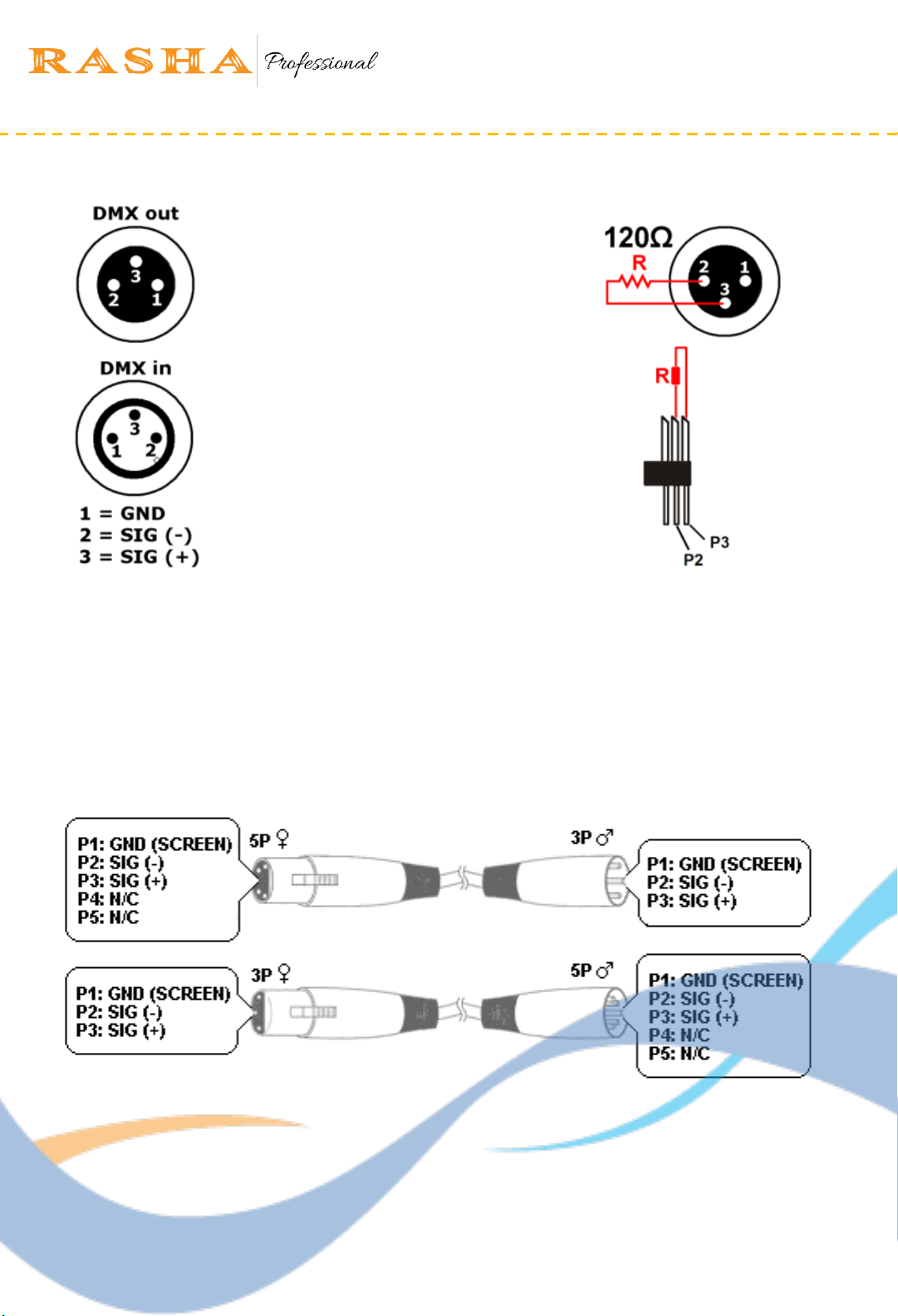
▪Connect the DMX input from your slave device to the DMX output of the previous device
in the chain.
▪Connect the slave device to the mains to switch it on.
▪Press MENU to enter the menu.
▪Navigate to <Slave Mode> with UP or DOWN and press ENTER to confirm.
▪Select <Slave Mode [YES]> with UP or DOWN and press ENTER to confirm.
▪Repeat these steps for all slave units.
Master Unit
▪Connect the master device to the mains to switch it on.
▪Press Menu to enter the menu.
▪Navigate to <Auto Mode> with UP or DOWN and press ENTER to confirm.
▪Select <Auto Mode> with UP or DOWN and press ENTER to confirm.
▪Set the master unit to work in one of the running modes.
▪Connect the master unit as the first unit in the chain by connecting the DMX output of the
master device to the DMX input of the first slave unit.
5.5. Manual Mode
Set manual mode, which can adjust the RGB color
1. Press MENU to enter the menu.
2. Navigate to <Operation Mode> with UP or DOWN and press ENTER to confirm.
3. Select <Manual Mode> with UP or DOWN and press ENTER to confirm.
4. Navigate to <R G B> with UP or DOWN and press ENTER to confirm.
Use DMX Signal Cable connect the controller boxes.
5.6. DMX Mode
The DMX mode allows you to control the device with any universal DMX controller.
•All DMX-controlled devices need a digital start address so that the correct device responds
to the signals. This digital start address is the channel number from which the device
starts to “listen” to the DMX controller. The same starting address can be used for a whole
group of devices or an individual address can be set for every device.
▪When all devices have the same address, all the units will “listen” to the control signal on
one particular channel. In other words: changing the settings of one channel will affect all
devices simultaneously. If you set individual addresses, each device will “listen” to a
separate channel number. Changing the settings of one channel will only affect the
device in question.

11
Rasha Professional A/S | 1800 Rustin Ave, Riverside, CA, 92507 | 951-654-3585
Rashaprofessional.com | info@rashaprofessional.com
Attention
Start Addresses
After switching on, the device will automatically detect whether DMX 512 data is received or
not. If there is data received at the DMX input, the DMX LED next to the LCD display will flash.
If no DMX signal data is received? This situation can occur if:
−the XLR plug (cable with DMX signal from controller) is not connected with the input of
the device.
−the controller is switched off or defective, if the cable or connector is defective or the
signal wires are swap in the input connector.
To set the device to work with a DMX controller
* Press MODE until <DMX Address> is displayed and press ENTER.
* Use <UP> and <DOWN> to set the DMX start address and press ENTER.
Use the table below to define the correct address. The table shows the settings for units 1 to
3. Apply the same principle for the other units. Example:
Channel Mode
First Unit
Second Unit
Third Unit
Highest Start address
8
Start Address
19(1+8) 17(9+8) 505

12
Rasha Professional A/S | 1800 Rustin Ave, Riverside, CA, 92507 | 951-654-3585
Rashaprofessional.com | info@rashaprofessional.com
DMX –Protocol: 8 –Channel Mode:
Channel
DMX-Value
Function
1
000-255
Dimmer (0 - 100 %)
2
000-255
Strobe, increasing speed (0 - 100 %)
3
000-255
Red (0 - 100 %)
4
000-255
Green (0 - 100 %)
5
000-255
Blue (0 - 100 %)
6
000-015
No function
016-031
P1 –Program 1
032-047
P2 –Program 2
048-063
P3 –Program 3
064-079
P4 –Program 4
080-095
P5 –Program 5
096-111
P6 –Program 6
112-127
P7 –Program 7
128-143
P8 –Program 8
144-159
P9 –Program 9
160-175
P10
–Program 10
176-191
P11
–Program 11
192-207
P12
–Program 12
208-223
P13
–Program 13
224-239
P14
–Program 14
240-255
P15
–Program 15
7
000-015
No function
016-031
P16
–Program 1
032-047
P17
–Program 2
048-063
P18
–Program 3
064-079
P19
–Program 4
080-095
P20
–Program 5
096-111
P21
–Program 6
112-127
P22
–Program 7
128-143
P23
–Program 8
144-159
P24
–Program 9
160-175
P25
–Program 10
176-191
P26
–Program 11
192-207
P27
–Program 12
208-223
P28
–Program 13
224-239
P29
–Program 14
240-255
Pmix –Programs 1-29 in an endless loop
8
000-255
Increasing speed of the program settings under Channels 6and 7
Note: In order to change from DMX-Controlled operation back to Auto Mode operation,
Please disconnect the device from the DMX-controller.

13
Rasha Professional A/S | 1800 Rustin Ave, Riverside, CA, 92507 | 951-654-3585
Rashaprofessional.com | info@rashaprofessional.com
Art-Net Mode
First Step; Computer IP Settings, Using Internet protocol version 4 (TCP/IPv4 network
Settings).
5.2. Networking Setting-Art-Net Mode / Kling-Net Mode
1. For IP segment 002.0.0.1--002.0.0.255 , for example, a computer can be set to the address
002.0.0, X (X : you can set as 99 ,can also be the value of the other, as long as don't setting
the same with controller box)
2. Subnet mask can be 255.255.255.0 (also can be set into 255.0.0.0 or 255.255.0.0).Gateway
and must be consistent and DNS, the first three Numbers also must agree and IP.
3. Advice: close all outside net, close all security and anti-virus software.
Second Step: DMX Address Setting
When using Art-Net, unified use 001 addresses.

14
Rasha Professional A/S | 1800 Rustin Ave, Riverside, CA, 92507 | 951-654-3585
Rashaprofessional.com | info@rashaprofessional.com
Third Step: Controller Box Setting
In order to link the controller to Art-Net for more flexible control, please define your
parameters by choosing settings from the following three submenus:
- IP Address
an be arbitrarily changed, the numerical requirements and computers, and other Art-Net
device in the same gateway, IP segment is consistent, and IP can't conflict. Numerical range
for the standard IP address range, namely 0 ~ 255 Changes
- SubNet Mask
Subnet mask can be 255.255.255.0 (also can be set into 255.0.0.0 or 255.255.0.0).Gateway
and must be consistent and DNS, the first three Numbers also must agree and IP
- Net SubNet Universal
Can be used to change for the domain and the range is 000.00.00 to 000.16.16. According to
the way we put device(controller), in order to make changes. This value can be changed, in
behind the computer convenient irregular put after some adjustments. After confirmation,
click the MENU button to return to, universe setup complete.
Advice: start from 000.00.00
Kling-Net Mode
At power-up, the Blade is detected and configured automatically by Kling-Net. Refer to your
Kling-Net manual for more information.

15
Rasha Professional A/S | 1800 Rustin Ave, Riverside, CA, 92507 | 951-654-3585
Rashaprofessional.com | info@rashaprofessional.com
6. Cleaning and Maintenance
- All screws should be tightened and free of corrosion.
- The housing, the lenses, the mounting supports and the installation location (e.g. ceiling,
suspension, trussing) should not be deformed, modified or tampered with; e.g. do not drill
extra holes in mounting supports, do not change the location of the connections…
- Mechanically moving parts must not show any signs of wear and tear.
- The electric power supply cables must not show any damage. Have a qualified technician
maintain the device.
- -Disconnect the device from the mains prior to maintenance activities. Let the device cool
down.
- Wipe the device regularly with a moist, lint-free cloth. Do not use alcohol or solvents.
- Do not immerse the device in any liquid.
- There are no user-serviceable parts.
- Contact your dealer for spare parts if necessary.
Please Note: All information is subject to change without prior notice. Please contact to your
reseller for further questions
This manual suits for next models
1
Table of contents
Other RASHA PROFESSIONAL Light Fixture manuals
Popular Light Fixture manuals by other brands

Vimar
Vimar Eikon 20394 manual

Cooper Lighting Solutions
Cooper Lighting Solutions B95 LED installation instructions

EXC
EXC ECOLOR EC-C8240N quick start guide

Philips
Philips SpotOn Ultra 69141/14/PH brochure

RSA Lighting
RSA Lighting Combolight LV Series LV3000IS Specifications

Chauvet Professional
Chauvet Professional ROGUEOUTCAST2BEAM Quick reference guide