Rasmussen SR-2R User manual

REV.5/15/07 Page 1 of 4
ON
OFF
SIGNAL
LIGHT
ON/OFF
BUTTONS
WALL CLIP
SLOT
12V
BATTERY
COMPARTMENT
FRONT BACK
Part # SR-2R
REMOTE
LEARN
ADJ.
Requires 4-AA 1.5V
alkaline batteries
Learning
button
Frequency
adjusting
access hole
Battery cover slides on/off
Slide
Switch
REMOTE
OFF
OFF
Part # BPR-1
SR-2R INSTALLATION AND OPERATING INSTRUCTIONS
SINGLE-FUNCTION WIRELESS REMOTE CONTROL SYSTEM
FOR OPERATING ON/OFF SOLENOID
INTRODUCTION
This remote control system was developed to provide a safe, reliable, and user-friendly remote control system for gas heating
appliances. The system is operated manually from the transmitter. The system operates on radio frequencies (RF) within a 20' range
using non-directional signals. The system operates on one of 256 security codes that are programmed into the transmitter at the
factory; the remote receiver must learn the transmitter code prior to initial use.
Review THERMOSTAT SAFETY SECTION under RECEIVER section. This high temperature safety feature
shuts down the appliance when a potentially unsafe condition exists.
TRANSMITTER This remote control SYSTEM offers the user a battery-operated remote control to
power a DC solenoid to remotely turn the gas log set on, of.
The solenoid circuit uses the battery power from the receiver to operate a
solenoid. The circuit has reversing polarity software, which reverses the positive
(+) and negative (-) output of the receiver's battery power to operate the solenoid
ON/OFF. The remote transmitter controls the SYSTEM.
The transmitter operates on a 12V battery (A-23). Before using the transmitter
install the 12-volt battery in the battery compartment.
It is recommended that ALKALINE batteries always be used for longer battery life
and maximum operational performance.
The transmitter has ON and OFF functions that are activated by pressing the
buttons on the face of the transmitter. When a button on the transmitter is
pressed, a signal light on the transmitter illuminates to verify that a signal is being
sent. Upon initial use, there may be a delay of three seconds before the remote
receiver will respond to the transmitter. This is part of the system's design. If the
signal light does not illuminate, check the position of the transmitter's battery.
REMOTE RECEIVER
IMPORTANT
THE REMOTE RECEIVER SHOULD BE POSITIONED WHERE
AMBIENT TEMPERATURES DO NOT EXCEED 130° F.
The remote receiver (right) operates on four 1.5V AA-size batteries. It is
recommended that ALKALINE batteries be used for longer battery life and
maximum microprocessor performance. IMPORTANT: New or fully charged
batteries are essential to proper operation of the remote receiver as a servo
motor's power consumption is substantially higher than standard remote control
systems.
NOTE: The remote receiver will only respond to the transmitter when the 2-
position slide button on the remote receiver is in the REMOTE position. The
IF YOU CANNOT READ OR UNDERSTAND THESE INSTALLATION INSTRUCTIONS DO NOT
ATTEMPT TO INSTALL OR OPERATE

REV.5/15/07 Page 2 of 4
STV-10
Valve
STV-LS
Solenoid
LEARN
ADJ.
REMOTE
OFF
Part # BPR-1
Remote Receiver
Receiver
Slide
Button
REMOTE
OFF
SERVO MOTOR
Terminals
RED Wire
1/4” Female
Terminal
BLACK Wire
1/4” Female
Terminal
(Back of Receiver)
BLACK Wire
1/4” Female
Terminal
RED Wire
1/4” Female
Terminal
LEARN
ADJ.
Part # BPR-1
remote receiver houses the microprocessor that responds to commands from the
transmitter to control system operation.
FUNCTIONS:
•With the slide switch in the REMOTE position, the system will only
operate if the remote receiver receives commands from the
transmitter. Upon initial use, or after an extended period of no use,
the ON/HI button may have to be pressed for up to three seconds
before activating servomotor. If the system does not respond to the
transmitter on initial use, see MATCHING SECURITY CODES in
the GENERAL INFORMATION section.
•With the slide in the OFF position, the system is off.
•It is suggested that the slide switch be placed in the OFF position if
you will be away from your home for an extended period of time.
Placing the slide switch in the OFF position also functions as a
safety "lock out" by both turning the system OFF and rendering the
transmitter inoperative.
INSTALLATION INSTRUCTIONS
WARNING
DO NOT CONNECT REMOTE RECEIVER DIRECTLY TO 110-120VAC POWER. THIS WILL
BURN OUT THE RECEIVER. FOLLOW INSTRUCTIONS FROM MANUFACTURER OF GAS
VALVE FOR CORRECT WIRING PROCEDURES. IMPROPER INSTALLATION OF ELECTRIC
COMPONENTS CAN CAUSE DAMAGE TO GAS VALVE AND REMOTE RECEIVER, WHICH
IS NOT COVERED BY WARRANTY.
INSTALLATION
The remote receiver can be mounted on or near the fireplace hearth. PROTECTION FROM EXTREME HEAT IS VERY
IMPORTANT. Like any piece of electronic equipment, the remote receiver should be kept away from temperatures exceeding
130º F inside the receiver case. Battery life is also significantly shortened if batteries are exposed to high temperatures.
NOTE: INSTALLATION IN THE OPTIONAL CERAMIC LOG HOUSE (ITEM#RH2) IS HIGHLY
RECOMMENDED.
WIRING INSTRUCTION
CONNECTING THE RECEIVER TO THE GAS VALVE WITH THE ON/OFF SOLENOID
1. Connect the Black 18 gage stranded wire with the 1/4” female terminal from the receiver to the 1/4” male terminal on the valve
soleniod.
2. Connect the Red 18 gage stranded wire with the 1/4” female terminal from the receiver to the 1/4” male terminal on the valve
solenoid.
3. After receiver wires are connected to the valve solenoid terminals make sure the receiver shield is located over the receiver
and locate the receiver in an area that will not exceed 130° F.
IMPORTANT NOTE: Operation of these controls is dependent on which wire is attached to which terminal. If operation of
control does not correspond to operating buttons on transmitter, reverse wire installation at the receiver or at the control.
NOTE: Up to 6 VDC of pulse power is provided at the receiver terminal.

REV.5/15/07 Page 3 of 4
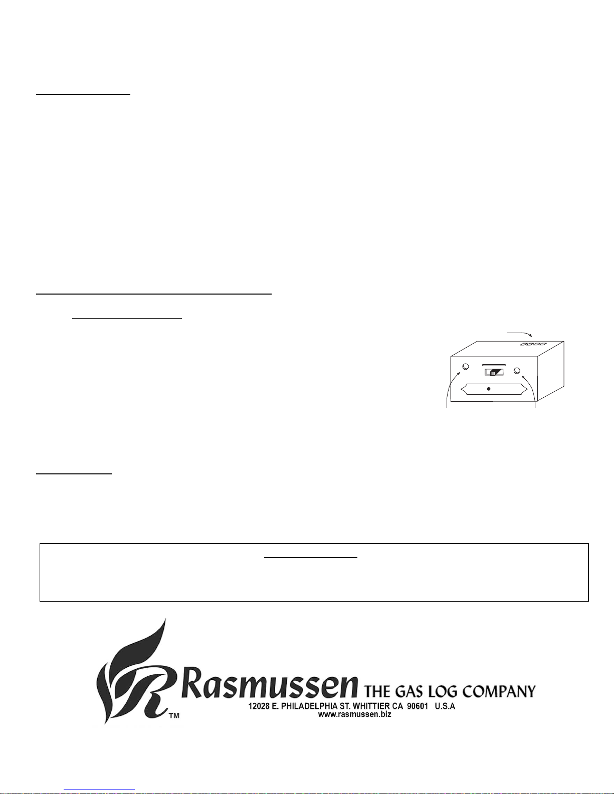
WALL CLIP
SLOT
WALL CLIP
12V
BATTERY
COMPARTMENT
Part # SR-2R
THERMOSTAT-SAFETY FEATURE – BPR-1 RECEIVER
When the ambient temperature at the THERMISTOR, inside the receiver case, reaches 130°F, the THERMISTOR will automatically
send 2 pulses of power to the off terminal on the valve to shut the fireplace system off and the RECEIVER will begin emitting a series of
2 "beeps" every 4 seconds. When the ambient temperature, at the RECEIVER, drops between 120° F and 130° F, the user can
reactivate the fireplace by pushing either button on the transmitter. When any transmitter button is pressed, the THERMISTOR "resets"
itself and the fireplace will begin operating again. However, the "beeping" will continue, if the ambient temperature remains between
120° F and 130° F. This "beeping" alerts the user that the RECEIVER should be repositioned so the ambient temperature drops below
120° F.
When the temperature drops below 120° F, the "beeping" will cease, providing the user has "reset" the THERMISTOR by pushing
either transmitter button to operate the fireplace. Allow sufficient time for receiver to cool below 120° F, and then press transmitter
button to stop beeping.
GENERAL INFORMATION
MATCHING SECURITY CODES
Each transmitter can use one of 256 unique security codes. It may be necessary to press the LEARN button on the remote
receiver accept the transmitter security code upon initial use, if batteries are replaced, or if a replacement transmitter is purchased
from your dealer or the factory. In order for the receiver to accept the transmitter security code, be sure the slide button on the
receiver is in the REMOTE position; the receiver will NOT "LEARN" if the slide switch is in the OFF position. Press the LEARN
button on the remote receiver to accept the transmitter security code by pressing in the LEARN button on the front of the remote
receiver and then pressing any button on the transmitter. A change in the beeping pattern, at the receiver, indicates the
transmitter's code has been accepted into the receiver. When an existing receiver has accepted the new transmitter, the new
security code will overwrite the old one.
The microprocessor that controls the security code matching procedure is controlled by a timing function. If you are unsuccessful
in matching the security code on the first attempt, wait 1 - 2 minutes before trying again--this delay allows the microprocessor to
reset its timer circuitry--and try up to two or three more times.
TRANSMITTER WALL CLIP
The transmitter can be hung on a wall using the clip provided. If the clip is
installed on a solid wood wall, drill 1/8" pilot holes and install with the
screws provided. If it is installed on a plaster/wallboard wall, first drill two
1/4" holes into the wall. Then use a hammer to tap in the two plastic wall
anchors flush with the wall; then install the screws provided.
OPERATION
1. This remote control will operate the gas valve solenoid to turn the gas valve from OFF to ON.
2. When the ON button is depressed the transmitter will send a RF signal to the receiver. The receiver then sends a 6 volt pulse
of power to operate the solenoid (ON).
3. When the OFF button is depressed the transmitter will send a RF signal to the receiver. The receiver then sends a 6 volt pulse
of power to operate the solenoid (OFF).
4. The remote control will only work with the hand held transmitter. The receiver slide switch is only for positive OFF or REMOTE
operation.
NOTE: Extensive operation ON-OFF solenoid will reduce the receiver's battery life significantly.
BATTERY LIFE
Life expectancy of the alkaline batteries in the SR-2R can be up to 12 months depending on use of the servomotor function. Check all
batteries annually. When the transmitter no longer operates the remote receiver from a distance it did previously (i.e., the transmitter's
range has decreased) or the remote receiver does not function at all, the batteries should be checked. It is important that the remote
receiver batteries are fully charged, providing combined output voltage of at least 5.0 volts. The transmitter should operate with as little
as 9.0 volts battery power.

REV.5/15/07 Page 4 of 4
LEARN
ADJ.
Wire terminals
Remote Receiver
Frequency adjusting
access hole Learning
button
REMOTE
OFF
Part # BPR-1
TROUBLE SHOOTING
If you encounter problems with your fireplace system, the problem may be with the fireplace itself or it could be with the SR-2R remote
system. Review the fireplace manufacturer's operation manual to make sure all connections are properly made. Then check the
operation of the remote in the following manner:
1. Make sure the batteries are correctly installed in the RECEIVER. One reversed battery will keep receiver from operating properly.
2. Check battery in TRANSMITTER to make sure contacts are touching (+) and (-) ends of battery. Bend metal contacts in for tighter
fit.
3. Be sure RECEIVER and TRANSMITTER are within 20'-25' operating range.
4. Keep RECEIVER from temperatures exceeding 120° F. Battery life shortened when ambient temperatures are above 115° F.
5. If RECEIVER is installed in tightly enclosed metal surround, the operating distance will be shortened.
NOTE: A receiver located in an area where the ambient temperature inside the case exceeds 130° F will cause the THERMOSTAT-
SAFETY feature to cut in, requiring you to reposition the receiver to stop the warning beeps and to "reset" the receiver's operation.
Due to handling and shipping of the unit, handling or dropping of the transmitter by the customer, and/or heat conditions at the receiver,
some receivers may need an occasional frequency adjustment. This adjustment is made to improve the communication and operating
distance between the transmitter and the receiver. Follow the steps below for making the adjustment.
FREQUENCY (DISTANCE) ADJUSTMENT PROCEDURE
RECEIVER ADJUSTMENT
1. To adjust at the receiver, use a small slotted screwdriver. Turn the adjustment
(ADJ) screw counter-clockwise about 5° or maximum of 1/8 turn. This should
correct the distance problem.
2. If that does not correct the problem, return adjustment screw to original
position and then turn adjustment screw clockwise.
This adjustment is like tuning your radio. If you keep turning the
adjustment screw, in either direction, you will go past the proper setting
(tuning).
SPECIFICATIONS
BATTERIES: Transmitter 12V - (A23)
Remote Receiver 6V - 4 ea. AA 1.5 Alkaline FCC ID No.'s: transmitter - K9L1001; receiver - K9L330IRX
Operating Frequency: 303.8 MHZ Canadian ISC ID No.'s: transmitter – 2439A-1001; receiver – 2439A-3301RX
FCC REQUIREMENTS
NOTE: THE MANUFACTURER IS NOT RESPONSIBLE FOR ANY RADIO OR TV INTERFERENCE CAUSED BY
UNAUTHORIZED MODIFICATIONS TO THIS EQUIPMENT. SUCH MODIFICATIONS COULD VOID THE USER’S
AUTHORITY TO OPERATE THE EQUIPMENT.
Table of contents
Other Rasmussen Remote Control manuals