UV-USA_CAN SCC_WE, CM_P V06, 11/2016 7
Dear customer,
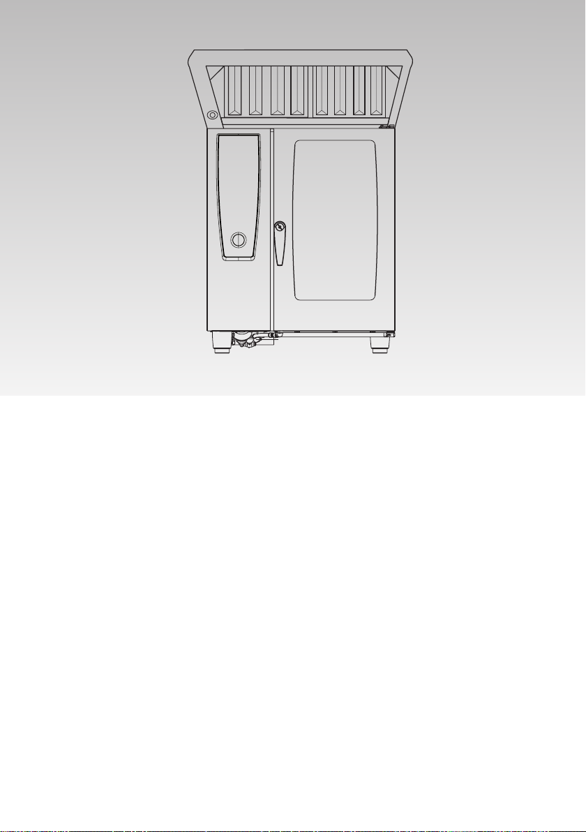
Please read this installation manual carefully before
installing the hood.
Attention:
- Ultravent can be used for SCC as well as-for CM
units 61/101/62/102
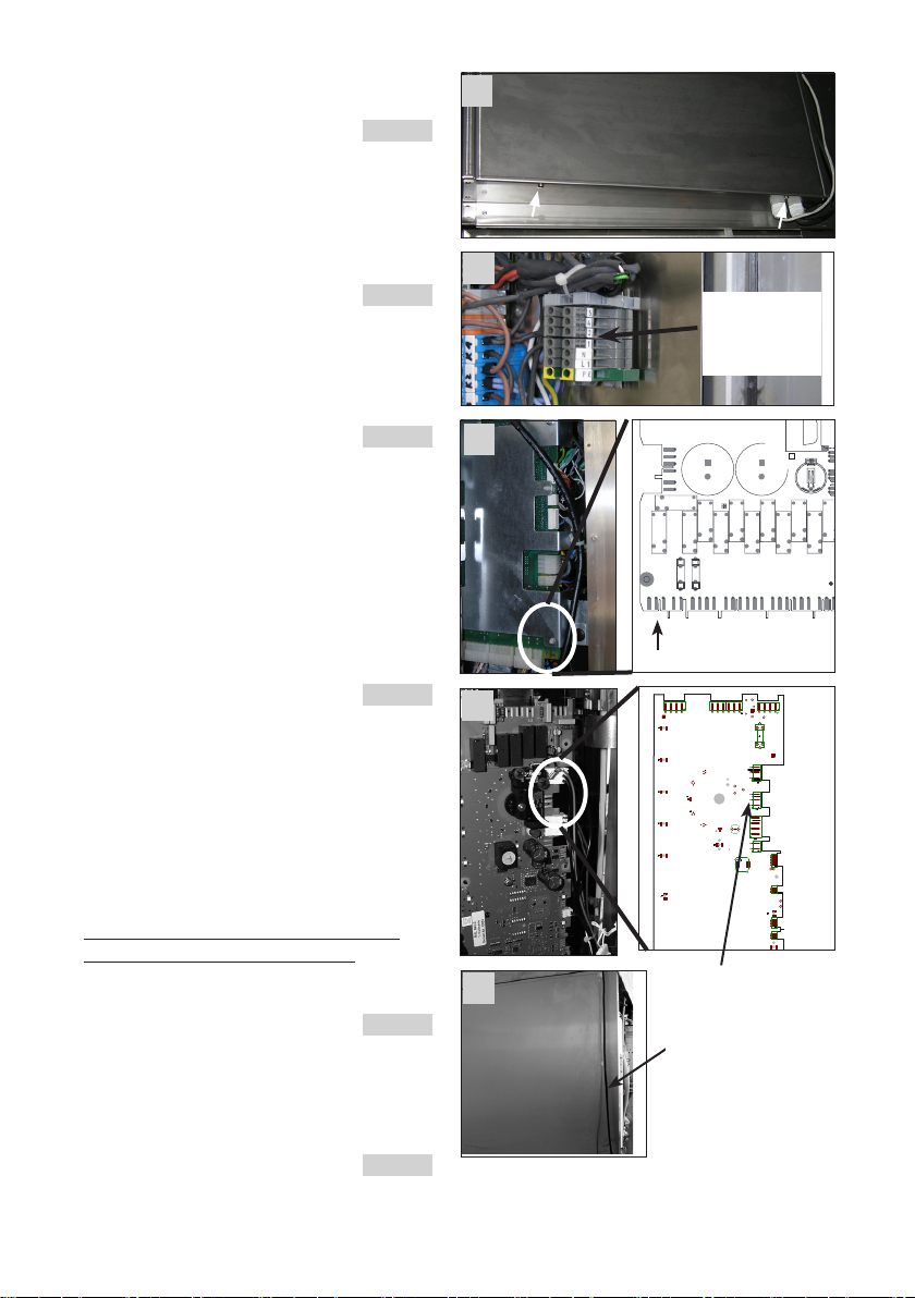
- Ultravent is equipped with a differential pressure
switch. This switch cuts out the function of the
Combi steamer, if the air flow through the char-
coal filters is reduced to approx. 75 % (charcoal
filter are soiled). The differential pressure switch
has to be set during installation (see page 12).
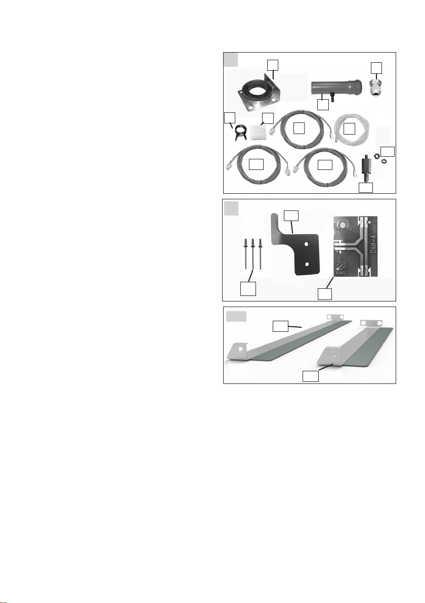
The following accessories are included in the Ultra-
vent set (see picture 1 and 2):
Item Description Part nos. Qty:
1 Gasket adapter vent pipe 62 60.72.433 1
Gasket adapter vent pipe 102 60.72.435 1
Gasket adapter vent pipe 61/101 60.72.431 1
2 Cable gland 40.00.320 2
3 Connection cable to terminal X23 (W26) 1
40.02.008
4 Self adhesive cable clip 10.01.293 5
5 Drain pipe 60.70.735 1
6 Silicon hose apprx.5ft
2110.1008
7 Hose clip 2066.0533 2
8 Connection cable 40.02.049 1
Interface pcb A8 to cpu pcb X27 (W23)
9 Connection cable 40.02.050 1
Interface pcb A8 to Ultravent 4/5 (W24)
10 Stud 60.72.892 1
11 Nut 1
12 Lock plate 60.73.055 1
13 Rivet 3
14 Interface pcb A8 42.00.031 1
Additional parts only 2/1 GN unit (pic. 2a)
15 Metal strip with rubber gasket (only 102) 1
- Rubber air deflector 60.73.932
16 Metal strip with rubber gasket (only 62) 1
- Rubber air deflector 60.73.942
Installation Manual
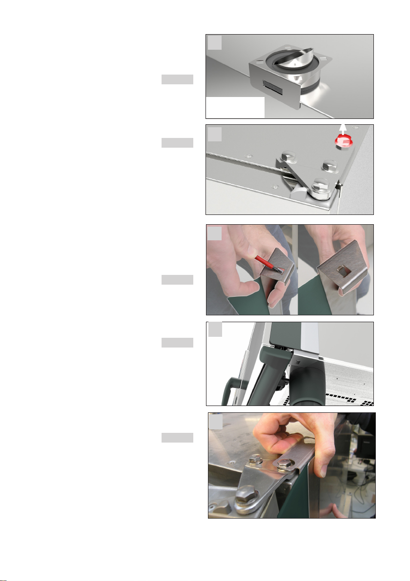
1. Delivery
Carefully unpack the unit on delivery and check to
ensure that no damage has been caused in transit
(follow the instructions on the packaging). Take all
packed parts out of Ultravent and unpack them.
212
112
3
74
6
5
89
14
13
15
2a
10
11
16