Rational UltraVent User manual

UV-USA SCC_WE, CM_P V04, 02/2013 1
UltraVent® (Condensation extractor hood)
61/101/62 Electric
for units produced as of 09/2011
UltraVent® (Hotte aspirante)
61/101/62 Électrique
pour les appareils fabriqués à partir de 09/2011

UV-USA SCC_WE, CM_P V04, 02/2013
2
Dear Installer,
Please follow strictly the guidelines given in this installation manual (page 3 - 12). Damages based on instal-
lation not complying with the directives given hereunder are not covered by warranty and liability terms.
Brief operating instructions page 13/14
Notes:
Cher installateur,
Veuillez vous conformer aux consignes de ce guide d'installation (pages 17 - 26). Les dommages causés
suite à une installation non conforme avec les directives de ce guide ne sont pas couverts par la garantie.
Manuel d'utilisation succinct page 27/28

UV-USA SCC_WE, CM_P V04, 02/2013 3
Connection diagram UltraVent® 62 (Measures in inch)
Connection diagram UltraVent® 61/101 (Measures in inch)

UV-USA SCC_WE, CM_P V04, 02/2013
4
Attention
12VDC between
terminal 4 and 5
1 2 4 5 L N
green
white
black/brown
white
brown
white
green
to X23 connector
A8 Door switch X27
use supplied
power cable
M1 gn/ye
M1 blue
M1 brown
M1 black
M2 gn/ye
M2 blue
M2 brown
M2 black
Aref. page 5

UV-USA SCC_WE, CM_P V04, 02/2013 5
Item Description Wiring Part nos.
diagram
1. Transformer Tr1 3037.0254
2. Pressure switch D1 3017.1014
3. Relay 110V 1U Rel1 40.04.302
4. Impulse relay Rel5 40.04.231
5. Time Relay Rel4 3035.0393
6. Relay 24V 2U Rel2 40.04.303
7. Relay 24V 2U Rel3 40.04.303
8. Bridge rectifier Br 1 40.03.367
9. Fuse 0,315A F2 + F3 3019.0135
10. Fuse 6,3A F1 3019.0122
11. Transformer 110>24V Tr2 3037.0254
12. Mini contactor 24V K3 40.04.306
13. Contactor 24V K1 40.04.305
14. Contactor 24V K2 40.04.305
15. Fuse 6,3A F4 to F7 3019.0122
16. Capacitor 14 ȝF C1,C2 40.04.229
17. Capacitor 40 ȝF C3,C4 40.04.230
Description Part nos. Qty.
Interface pcb A 8 42.00.031 1
Control cable W26 40.02.008 1
Control cable W23 40.02.049 1
Control cable W24 40.02.050 1
Magnet Y1 (solenoid) 3035.0494 1
Main switch T1 40.04.356 1
LED green LED3 40.04.308 1
LED red LED2 40.04.166 1
LED yellow LED1 40.04.165 1
Extractor fan, size 61/101 60.72.701 2
Extractor fan, size 62 60.72.701 2
Fat filter (left side) 60.72.440 1
Fat filter (right side) 60.72.441 1
Fiber media filter 60.72.556 1
Gasket adapter (item. 1) 61/101 60.72.431 1
Gasket adapter (item. 1) 62 60.72.433 1
Drain pipe (item 5) 60.70.735 1
Silicone hose Ø 10 mm 2110.1008 1
1
2
3
4
5
6
7
9
10
11
8
12
13
14
15
16 17
A

UV-USA SCC_WE, CM_P V04, 02/2013
6
Dear customer,
Please read this installation manual carefully before
installing the hood.
Attention:
- Ultravent can be used for SCC as well as-for
CM units 61/101/62
- Ultravent is equipped with a differential pres-
sure switch. This switch cuts out the function
of the Combi steamer, if the air flow through
the charcoal filters is reduced to
approx. 75 % (charcoal filter are soiled)
The differential pressure switch has to be set
during installation (see page 11).
The following accessories are included in the
Ultravent set (see picture 1 and 2):
Item Description Qty.:
1 Gasket adapter vent pipe 1
2 Cable gland 2
3 Connection cable to terminal X23 (W26) 1
4 Self adhesive cable clip 5
5 Drain pipe 1
6 Silicon hose apprx. 5 ft
7 Hose clip 2
8 Connection cable 1
Interface pcb A8 to cpu pcb X27 (W23)
9 Connection cable 1
Interface pcb A8 to Ultravent 4/5 (W24)
10 Stud 1
11 Nut 1
12 Lock plate 1
13 Rivet 3
14 Interface pcb A8 1
Additional parts only 6x2/1 GN unit (pic. 2a)
15 Deflector 1
16 Bit 1
17 Tap die 1
18 Screws 4
- Rubber air deflector
Installation Manual
1. Delivery
Carefully unpack the unit on delivery and check
to ensure that no damage has been caused in
transit (follow the instructions on the packag-
ing). Take all packed parts out of Ultravent and
unpack them.
212
112
3
74
6
5
89
14
13
15
16 17 18
2a
10
11

UV-USA SCC_WE, CM_P V04, 02/2013 7
2. Installation of the extractor hood
2.1 Fitting the hood on the combi-steamer:
- Disconnect combi steamer from mains
- Put the gasket (pic 1. item 1) over the unit’s vent
pipe (observe installation direction) pic. 3
- Check door of the unit for correct adjustment
- Replace rear screw of the top door holding
plate by stud (item 10) and washer. pic. 4
- Carefully place Ultravent onto unit pic. 5
- Remove fat and fiber media filter
- Fasten UV/EH with nut and washer (pic1 item11)
to previous installed stud. pic. 6
- Open left side panel
- There are knock outs in the bottom panel of the
electric compartment. Break one of these out
and fix the cable gland (pic. 1 Item 2) into it
pic. 7
7
3
Cable gland
Gasket adapter
vent pipe (item 1)
4
6
5

UV-USA SCC_WE, CM_P V04, 02/2013
8
12
Fix with self adhesive
cable clips
9
Term.: 1/2
Control cable to
pcb X23 (W26)
10
K8
X18
K2
K1
K5
X19
X75
K4
K3
K10
K9
G3
+
X23 X20
F1
F2
X21
K6
K7
K11
K12
X14
+
X13
LED V68
F2
2AT
F1
2AT
From Ultravent (term. 1/2)
X26
X27
X8
X11
X13
X14
X23
X21
X18X19X20
F1
From Ultravent (term. 1/2)
2.2 Fitting the control cable
- On the rear of the UltraVent® there is a power
box; open it by loosing the screws. pic. 8
- For connection run cables through correspon-
ding cable glands into power box.
- The control cable W26 (pic. 1 item 3) is included
in the Ultravent kit. Connect this cable as
follows: pic. 9
- on SCC_WE-units: pic. 10
Connect control cable W26 to terminal X23 of
the cpu pcb
- on CM_P-units: pic. 11
Connect the control cable W 26 to X23 of the
operator pcb
- Run the cable back out through the cable gland
and up the back of the Combi-Steamer to the
power box of the Ultravent®.
- The control cable has a green, a white and
brown wire.
- For the connection of the Ultravent only the
green and the white wire are needed.
Connect the green wire to terminal 1 and the
white wire to terminal 2 of the power box
Ultravent pic 9
Insulate the brown wire
- The cable can be affixed to the back of the appli-
ance with the self-adhesive cable clips supplied
(pic1 item 4) pic. 12
8
11

UV-USA SCC_WE, CM_P V04, 02/2013 9
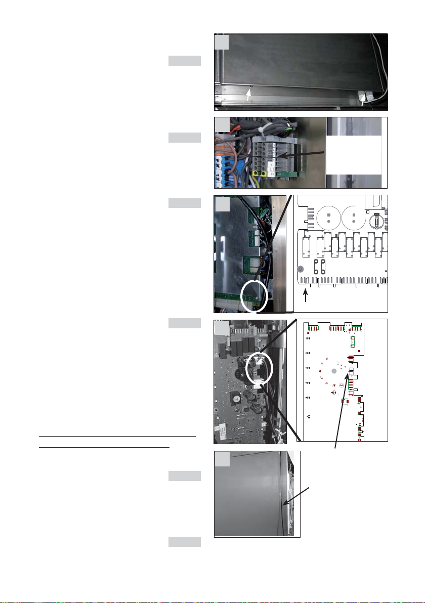
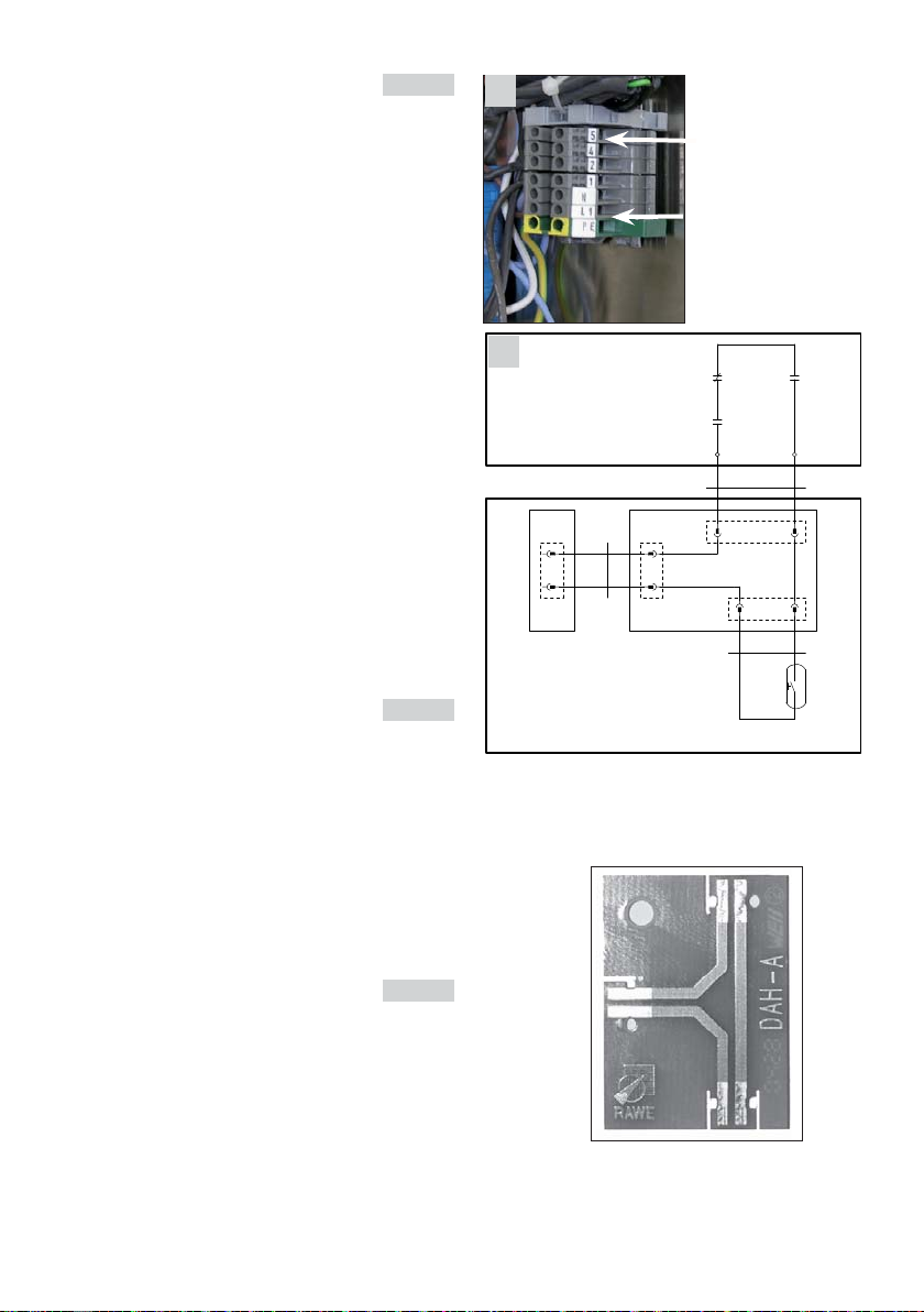
2.3 Power supply of the hood pic. 13
- The Ultravent must electrically be connected in
accordance with the local regulations.
Before removing the plug or reconnecting to the
power supply, ensure that the operating switch is
in the "off” position.
- The Ultravent is delivered without power cord.
The terminals for power connection can be found
in the power box at the rear side of the Ultravent.
The color code of the terminals are:
PE = earth yellow/green (ground)
L = phase grey
N = neutral blue
- Also on the rear side of the hood there is an
earth connection stud. Fit the hood with a
suitable cable to the earth bonding (ground)
system
2.4 The combination of Rational Combi and
Ultravent is electrically interlocked. The
Combi shall only operate under the follow-
ing conditions:
a) The UV must be electrically switched "ON”
b) All filters (charcoal filter and fat filter) must
be correctly installed. This is controlled by
additional reed switches.
c)Charcoal filters must be clean
To connect this circuit proceed as follows:
pic 14
1. There is an extra interface pcb (A8) delivered
with the Ultravent kit. Fix it to the electrical
mounting plate of the combi at a suitable posi-
tion.
2. In the kit also cable W24 (pic 1 item 9) is sup-
plied. Connect this cable to X23.1 of the interface
pcb (A8).
3. Run this cable W24 out of the electric compart-
ment through the cable gland back up to the
power box of the Ultravent. Connect brown wire
to terminal 4 and black wire to terminal 5 of the
power box. pic 13
4. Remove 2 pole connector X27 (door contact
switch)
from cpu pcb (SCC_WE units) or X27
operator pcb (CM_P units)
5. Connect the door contact switch to terminal
X27.2 of the interface board A8.
6.
Also in the kit there is the cable W 23 (pic. 1 item 8).
Connect this cable to X27.1 of the interface pcb
(A8) and the other end to X27 of the operator
pcb (CM_P units) respectively to X27 of the cpu
pcb (SCC_WE units).
13
X27.2
12
X23.1
12
X27.1
1
2
X27
11
22
A1
I/O-PCB (SCC)
CPU-PCB (SCC_WE)
4
5
W23
Rel3
Error relay
Rel2
Filter relay
Ultravent
Combi steamer
W24
S3
Door contact switch
W25
A8
Interface pcb
Operator-PCB (CM, CM_P)
Rel1
“On” relay
terminal 4 and 5 to
X23.1of A8
14
X23.1
X27.2
X27.1
A8
Mains input
PE = earth yellow/green
L = phase grey
N = neutral blue

UV-USA SCC_WE, CM_P V04, 02/2013
10
17
18
19
15
6
7
16 6
5
2.5 Condensation water
- At the rear side of the Ultravent there is a drain
connection for the condensated water inside the
hood.
- Connect the silicone hose (pic. 1 pos 6) with the
hose
clips (pic. 1 pos. 7) to the drain tube
pic 15
- Put the drain pipe (pic 1 pos. 5) to the unit’s
drain pic. 16
- Shorten the silicone hose (pic. 1 pos 6) to the
desired length and push it over the connection
piece of the drain pipe (pic. 1 pos. 5) pic. 16
- Ensure there are no kinks or sags in the hose.
Cut length to fit depending on unit size
3. Installation of the lock plate.
a) Use lock plate (pic 2 item 12) as a template.
Hold it to the top edge of the door and mark
the two holes. pic. 17
b) Drill two holes (3,2 mm approx. 1/8”) at the
marked positions into the door frame
c) Hold lock plate (pic 2 item 12) to top edge of the
door and fix the plate with the rivets (item 13)
pic. 18/19

UV-USA SCC_WE, CM_P V04, 02/2013 11
Piece of paper
Diff. press. switch
20
21
22
4. Setting of the differential pressure switch:
After the Ultravent has been installed, the
differential pressure switch must be adjusted to
the ambient conditions:
Attention: During the entire adjustment procedure
make sure that the charcoal filters
remain positioned. Otherwise the filter
switches (which are located behind the
filters) will set the combi steamer out of
function.
a) Remove fat filter pic 20
b) Connect Ultravent and Combi Steamer to mains.
c) Switch on Ultravent and Combi Steamer (select
cooking mode, time, temperature and close
unit’s door).
d) Set adjusting disc of the pressure switch to
zero position. pic. 21/22
In case of pressure switch of company Honey-
well back out screw
e) Block two third of the surface of the charcoal
filter with a piece of paper (= reduction of air flow
to 75%).
f) Turn adjusting disc of the pressure switch out
of the zero position, until the combi steamer
cuts out.
g) Remove the piece of paper. Now the combi
steamer should run again.
h) Reassemble the unit and perform a test run.
Rear side of Ultravent
Front view after
removing fat
filter

UV-USA SCC_WE, CM_P V04, 02/2013
12
The following description is only valid for 6x2/1GN
units
5. Installation of door deflector
(Pic. 24 item 15):
a) The necessary tools and screws are in a little
plastic bag that is taped to the deflector
pic. 23
b) The deflector must be installed to the right
outer edge of the door. pic. 25
c) Use the deflector as a template and mark the
three positions where the holes of the screws
must be drilled (use the supplied bit) pic. 26
The top edge of the deflector and of the door
must be even
d) For tapping us the supplied tap die
e) Fit the deflector with the screws to the door
g) Align the deflector in horizontal direction
When opening the door the deflector shall
close the gap between the door gasket and the
door. pic. 27
Gap closed by deflector
23
24
25
26
27
15

UV-USA SCC_WE, CM_P V04, 02/2013 13
Brief operating instructions
The combination of Rational Combi and Ultravent is
electrically interlocked. The Combi shall only oper-
ate under the following conditions:
a) The UV must be electrically switched "ON”
b) All filters (charcoal filter and fat filter) must be
correctly
installed, otherwise a "close door" error
will result. This is controlled by additional reed
switches.
c) The filters must be relatively clean. This is con-
trolled by a differential pressure switch. In case
the filters are soiled the yellow warning light
(located on the right side of the Ultravent) comes
on and the unit cuts out with close door error.
A) Operation:
Switching on the UltraVent® extractor hood:
Press main ON push button
Extractor runs continuously at low fan speed when
the door of the oven is closed (reduced suction)
On opening the oven’s door the UV power is
automatically increased to full fan speed (maxi-
mum extraction). During the first 50 seconds the
door can only be opened partially (door remains
locked by the locking system of the hood). After
the 50 seconds have elapsed, it is possible to
open the door completely.
When closing the oven’s door, automatically the
UltraVent® switches back to reduced suction (low
fan speed).
Note: if operation is reversed (low and full fan
speed) please review to installation instruc-
tions page 8 referencing connection of X23
to term 1 and 2 using the White / Green wires
only.
Note: Combi steamer will not work if:
- Ultravent is set to off or
- any of the filters are removed or
- filters are blocked with impurities or fat
("close door" displayed on combi steamer)
Safety instructions:
Caution: Risk of burning!
Parts may become hot.
Always ensure that before any maintenance work
the electrical plug is disconnected and the grease
filter has cooled.
Do not clean using high-pressure cleaning appli-
ances.
Clean exterior surface with a mild soap and water
solution using a rag or similar.
Ensure that the extractor vent is not clogged.
Ensure when taking the hood out of function for a
longer period of time, or during cleaning, that it is
disconnected from power.
Note: Filters:
Carbon and fiber media filter are not clean-
able. Replace and dispose of properly.

UV-USA SCC_WE, CM_P V04, 02/2013
14
B) Cleaning:
Clean the fat filters and the area behind the fat
filters at least once a week.
Attention: “When not cleaning the filters regularly
there is a danger of fire”
Push the fat filter upwards (first to the right)
pic. A
Pull the lower grease trap forward and remove from
the hood.
The fat filter can be cleaned in a dishwasher.
Reverse procedure to reassemble
C) Changing charcoal filters:
The charcoal filter is located behind the fat filters
and should be inspected for contaminants on a
regular basis. They have to be changed at least
every 3 months (do not clean in dishwashers):
1. Disconnect hood from mains
2. Remove fat filter as described above pic. A
3. Remove fiber media filter
4. Remove active carbon filter by pulling it out
pic. B
5. Pull out filter of cartridge,
6. Change filters
7. Make sure that the white fiber media filter faces
to the front
Attention:
Filter white to the side of the handle, pic. B
Filter black to fan side
6. Reverse procedure to reassemble
7. Make sure all filters are installed correctly, other-
wise the unit will not work.
A
B
Charcoal filter

UV-USA SCC_WE, CM_P V04, 02/2013 15
Ultravent
Cleaning and maintenance schedule
Installation date:
RECOMMENDED TIME FRAMES
Grease filter and metal housing
WEEK 1 WEEK 2 WEEK 3
WEEK 4 WEEK 5 WEEK 6
WEEK 7 WEEK 8 WEEK 9
WEEK 10 WEEK 11 WEEK 12
WEEK 13 WEEK 14 WEEK 15
WEEK 16 WEEK 17 WEEK 18
WEEK 19 WEEK 20 WEEK 21
WEEK 22 WEEK 23 WEEK 24
WEEK 25 WEEK 26 WEEK 27
WEEK 28 WEEK 29 WEEK 30
WEEK 31 WEEK 32 WEEK 33
WEEK 34 WEEK 35 WEEK 36
WEEK 37 WEEK 38 WEEK 39
WEEK 40 WEEK 41 WEEK 42
WEEK 43 WEEK 44 WEEK 45
WEEK 46 WEEK 47 WEEK 48
WEEK 49 WEEK 50 WEEK 51
WEEK 52
WEEKLY
Minimum every 2 weeks
MINIMUM
every 3 months
Charcoal filter replacement
JANUARY
FEBRUARY
MARCH
APRIL
MAY
JUNE
JULY
AUGUST
SEPTEMBER
OCTOBER
NOVEMBER
DECEMBER

UV-USA SCC_WE, CM_P V04, 02/2013
16
Notes :

UV-USA SCC_WE, CM_P V04, 02/2013 17
Schéma des branchements UltraVent® 62 (unités de mesure en pouces)
Schéma des branchements UltraVent® 61/101 (unités de mesure en pouces)

UV-USA SCC_WE, CM_P V04, 02/2013
18
Attention
12VDC between
terminal 4 and 5
1 2 4 5 L N
green
white
black/brown
white
brown
white
green
to X23 connector
A8 Door switch X27
use supplied
power cable
M1 gn/ye
M1 blue
M1 brown
M1 black
M2 gn/ye
M2 blue
M2 brown
M2 black
Aref. page 19

UV-USA SCC_WE, CM_P V04, 02/2013 19
Pce. Désignation plan Référence
de câblage
1. Transformateur Tr1 3037.0254
2. Pression différentielle D1 3017.1014
3. Relais 110V 1U Rel1 40.04.302
4. Relais à impulsions Rel5 40.04.231
5. Relais temporisé Rel4 3035.0393
6. Relais 24V 2U Rel2 40.04.303
7. Relais 24V 2U Rel3 40.04.303
8. Redresseur en pont Br1 40.03.367
9. Fusible 0,315A F2 + F3 3019.0135
10. Fusible 6,3A F1 3019.0122
11. Transfor.110>24V Tr2 3037.0254
12. Contacteur mini 24V K3 40.04.306
13. Contacteur 24V K1 40.04.305
14. Contacteur 24V K2 40.04.305
15. Fusible 6,3A F4 à F7 3019.0122
16. Condensateur 14 ȝF C1,C2 40.04.229
17. Condensateur 40 ȝF C3,C4 40.04.230
Désignation Référe. Qté.
Interface pcb A 8 42.00.031 1
Câble de commande W26 40.02.008 1
Câble de commande W23 40.02.049 1
Câble de commande W24 40.02.050 1
Aimant Y1 (électro-aimant) 3035.0494 1
Interrupteur principal T1
40.04.356
1
DEL verte LED3 40.04.308 1
DEL rouge LED2 40.04.166 1
DEL jaune LED1 40.04.165 1
Ventilateur d'extraction, taille 61/101 60.72.701 2
Ventilateur d'extraction, taille 62 60.72.701 2
Filtre à graisse (côté gauche) 60.72.440 1
Filtre à graisse (côté droit) 60.72.441 1
Filtre à fibres 60.72.556 1
Adaptateur pour joint (pièce 1) 61/101 60.72.431 1
Adaptateur pour joint (pièce. 1) 62 60.72.433 1
Conduite d'évacuation (pièce 5) 60.70.735 1
Flexible en silicone Ø 10 mm 2110.1008 1
1
2
3
4
5
6
7
9
10
11
8
12
13
14
15
16 17
A

UV-USA SCC_WE, CM_P V04, 02/2013
20
Cher client,
Veuillez lire attentivement le manuel d'installation
avant de procéder à l'installation de la hotte.
Attention :
- Ultravent peut être utilisée avec les appareils
SCC et CM 61/101/62
- Ultravent est dotée d'un contact à pression dif-
férentielle Le contact à pression différentielle
se charge d'arrêter le four mixte lorsque le flux
d'air dans le filtre à charbon est réduit
à env. 75% (filtre encrassé)
Le contact à pression différentielle doit être
réglé durant l'installation (voir page 25).
Les accessoires suivants sont inclus dans le kit
Ultravent (voir figures 1 et 2) :
Pièce Désignation Qté. :
1 Adaptateur pour joint tuyau d'air 1
2 Presse-étoupe câbles 2
Câble de connexion au terminal X23 (W26) 1
4 Attache-câble autocollante 5
5 Conduite d'évacuation 1
6 Flexible en silicone env. 5 ft
7 Attache-tuyau 2
8 Câble de connexion 1
Interface pcb A8 vers cpu pcb X27 (W23)
9 Câble de connexion 1
nterface pcb A8 vers Ultravent 4/5 (W24)
10 Boulons de serrage 1
11 écrou 1
12 Tôle de sécurité 1
13 Rivet 3
14 Interface pcb A8 1
Pièces supplémentaires uniquement 6x2/1 GN
appareil (fig. 2a)
15 Déflecteur 1
16 Bit 1
17 Taraud 1
18 Vis 4
- Déflecteur en caoutchouc
Manuel d'utilisation
1. Livraison
Déballez l'appareil avec précaution lors de la
livraison et vérifiez qu'il n'a subi aucun dommage
pendant le transport (suivez les instructions sur
l'emballage). Déballez l'ensemble des éléments
fournis.
212
112
3
74
6
5
89
14
13
15
16 17 18
2a
10
11
Table of contents
Languages:
Other Rational Ventilation Hood manuals