Ravaglioli RAV540U User manual

0579-M090-0 Rev. n. 4 (07/18)
SOLLEVATORE ELETTROIDRAULICO
ELECTRO-HYDRAULIC LIFT
RAV540U - RAV540IU
Redatto da S.D.T. S.r.l.
0579-M090-0
Per eventuali chiarimenti interpellare il più vicino rivenditore oppure rivolgersi direttamente a:
Servizio assistenza tecnica: RAVAGLIOLI S.p.A - Via 1° Maggio, 3 - 40037 Pontecchio Marconi - Bologna Italia
For any further information please contact your nearest dealer or speak directly to:
Technical services: RAVAGLIOLI S.p.A. - Via 1° Maggio, 3 - 40037 Pontecchio Marconi - Bologna Italy
ITALIANO:ISTRUZIONIORIGINALI
ENGLISH: TRANSLATION OF THE ORIGINAL INSTRUCTIONS
READ ALL INSTRUCTIONS.
INSTRUCTIONS MUST BE READ THOROUGHLY BEFORE INSTALLING, OPERATING OR MAINTAINING THE LIFT.
SAVE THIS INSTRUCTIONS
DELIVER THE LIFT-SPECIFIC, OPERATION, INSPECTION, AND MAINTENANCE INSTRUCTIONS
TO LIFT OWNER/USER/EMPLOYER ALONG WITH THE OTHER INSTRUCTIONAL MATERIALS FURNISHED WITH THE LIFT.

22 0579-M090-0
SIMBOLOGIA UTILIZZATA NEL MANUALE
SYMBOLS USED IN THE MANUAL
SIMBOLI SYMBOLS ZEICHEN SYMBOLES SÍMBOLOS
VIETATO! FORBIDDEN! VERBOTEN! PROHIBE! PROHIBIDO!
Indossare guanti da
lavoro Wear work gloves
Der Arbeit ange
messene Handschuhe
tragen
Porter des gants de
travail
Llevar guantes de
trabajo
Calzare scarpe da lavoro Wear work shoes Der Arbeit angemessene
Shuhe tragen
Mettre des chaussures
de travail Usar zapatos de trabajo
Indossare occhiali di
sicurezza Wear safety goggles Schutzbrille tragen Porter des lunettes de
sécurité
Colocarse gafas de
seguridad
Indossare l'elmetto
protettivo Wear protective helmet Schutzhelmpficht Porter un casque de
protection
Usar el casco de
protección
Pericolo di scariche
elettriche Shock hazard Gefahr: elektrische
Entladungen Danger d'électrocution Peligro descargas
elèctricas
Pericolo! Attenzione agli
organi meccanici in
movimento
Danger! Moving
mechanical parts
Gefahrt! Bewegliche
mechanische Organe
Danger! Organes
mécaniques en
mouvement
Peligro! Partes
mecánicas en
movimiento
Pericolo di
schiacciamento Crushing danger Gefahrt! Quetschgefahr Risque d'ecrasement Peligros de
aplastamiento
Attenzione carichi
sospesi Caution: hanging loads Achtung hängende
Lasten
Attention: charges
suspendues
Atenciòn cargas
suspendidas
Obbligo. Operazioni o
interventi da eseguire
obbligatoriamente
Mandatory.
Operations or jobs to be
performed compulsorily
Pflicht.
Obligatorisch
auszuführende
Arbeitsvorgänge oder
Eingriffe
Obligation.
Operations ou
interventions a realiser
obligatoirement
Obligación.
Operaciones o
intervenciones que hay
que realizar
obligatoriamente
Pericolo! Prestare
particolare attenzione.
Danger! Be particulary
careful
Gefahrt! Äusserste
Vorsicht ist geboten
Danger! Faire trés
attention
Peligro! Prestar especial
atención
Movimentazione con
carrello elevatore o
transpallet
Move with fork lift truck
or transpallet
Transport mit
Gabelstapler oder
Handgabelhub-
Déplacement avec
chariot élévateur ou
transpallet
Desplazamiento con
carretilla elevadora o
transpallet
Sollevamento dall'alto Lift from above Anheben von oben Levage par le haut Elevaciòn desde arriba

33
0579-M090-0
COMPOSITION OF MANUAL
74 pages (including cover pages)
COMPOSIZIONE DEL MANUALE
74 pagine (copertine comprese)
ATTENZIONE!
CAUTION!
This manual is part of the product and it must follow the operational life of the lift.
In addition to the manual, the following documents are supplied: the Manual ALI / SM07-1 “Lifting It Right”, the ALI/ST-05 “Safety
tips card”, the ANSI / ALI ALOIM-2008 “Safety Requirements for Operation, Inspection and Maintenance “and in the case of
frame engaging lifts, the guide ALI / LP” Vehicle Lifting Points / Quick Reference Guide for Frame Engaging Lifts. “
Keep all guides in a known location, easily accessible, and when in doubt do not hesitate to read them.
Any damage resulting from failure to follow instructions in this manual or a misuse of the lifting equipment disclaims the manufacturer
from any liability.
Il presente manuale costituisce parte integrante del prodotto, dovrà seguire tutta la vita operativa del sollevatore. Ad integrazione
del manuale sono dati in dotazione anche i seguenti documenti: il manuale ALI / SM07-1 “Lifting it right”, la ALI/ST-05 “Safety
tips card”, la ANSI / ALI ALOIM-2008 “Safety Requirements for Operation, Inspection and Maintenance” e, nel caso di
sollevatori che agganciano il telaio del veicolo, la guida ALI/LP “Vehicle Lifting Points/Quick Reference Guide for Frame
Engaging Lifts”. Conservarli, quindi, in un luogo noto e facilmente accessibile e consultarli ogni qualvolta sorgano dubbi. Tutti
gli operatori devono poterli leggere.
Ogni danno derivante dalla mancata osservanza delle indicazioni contenute nel presente manuale e da un uso improprio del
sollevatore esime il costruttore da ogni responsabilità.

44 0579-M090-0
INDICE
0. NORME GENERALI DI SICUREZZA ...................................................................................6
0.1 ISTRUZIONI DI SICUREZZA IMPORTANTI .........................................................................7
0.2 Dispositivi di sicurezza ......................................................................................................................................................... 8
0.3 Indicazione dei rischi residui.............................................................................................................................................. 14
1. DESTINAZIONE D'USO .....................................................................................................17
1.1 Accessori ............................................................................................................................................................................ 18
2. MOVIMENTAZIONE E PREINSTALLAZIONE ...................................................................21
3. DESCRIZIONE DEL SOLLEVATORE................................................................................22
3.1 Attitudine all'impiego .......................................................................................................................................................... 22
3.2 Caratteristiche tecniche principali ...................................................................................................................................... 22
3.3 Comandi ............................................................................................................................................................................. 22
3.4 Accessori a richiesta .......................................................................................................................................................... 23
3.5 Accessori forniti .................................................................................................................................................................. 23
4. INSTALLAZIONE................................................................................................................24
4.1 Verifica dei requisiti minimi richiesti dal luogo di installazione ......................................................................................... 24
4.2 Preparazione dell’area di installazione RAV540U ............................................................................................................ 25
4.2.1 Installazione speciale a richiesta per RAV540U................................................................................................................ 27
4.3 Preparazione dell'area di installazione RAV540IU .......................................................................................................... 29
4.4 Posizionamento delle pedane e collegamento dell'impianto in posizione standard RAV540U ..................................... 30
4.5 Posizionamento delle pedane e collegamento dell'impianto in posizione standard RAV540IU .....................................32
4.6 Allacciamento alla rete ....................................................................................................................................................... 35
4.7 Collegamento cavo alimentazione .................................................................................................................................... 35
4.8 Collegamento impianto pneumatico .................................................................................................................................. 37
4.9 Spurgo aria ......................................................................................................................................................................... 39
4.10 Fissaggio del sollevatore ................................................................................................................................................... 41
4.11 Verifica delle sicurezze....................................................................................................................................................... 41
4.12 Montaggio rampine di salita ............................................................................................................................................... 43
4.13 Registrazione livellamento rampine .................................................................................................................................. 43
4.14 Montaggio supporto rampa - RAV540IU ............................................................................................................................ 45
4.15 Fissaggio coperture e centralina - RAV540U .................................................................................................................... 45
4.16 Funzionamento del sollevatore .......................................................................................................................................... 45
4.17 Prova funzionale del sollevatore........................................................................................................................................ 45
5. ISTRUZIONI PER L'USO DEL SOLLEVATORE................................................................46
5.1 Uso improprio del sollevatore ............................................................................................................................................ 46
5.2 Uso di accessori ................................................................................................................................................................. 46
5.3 Addestramento del personale preposto ............................................................................................................................ 46
5.4 Precauzioni d'uso ............................................................................................................................................................... 47
5.5 Identificazione dei comandi e loro funzione ...................................................................................................................... 49
6. SICUREZZA .......................................................................................................................51
6.1 Procedura di emergenza.................................................................................................................................................... 51
6.2 Sicurezze ............................................................................................................................................................................ 51
7. MANUTENZIONE ...............................................................................................................52
7.1 Procedura di Lockout-Tagout del sollevatore .................................................................................................................... 52
7.2 Cambio olio centralina. ...................................................................................................................................................... 54
7.3 Pulizia elettrovalvole .......................................................................................................................................................... 54
7.4 Pulizia valvola regolatrice di portata .................................................................................................................................. 54
7.5 Lubrificazione ..................................................................................................................................................................... 55
7.6 Procedura manuale di riallineamento delle pedane ......................................................................................................... 57
8. INCONVENIENTI ................................................................................................................58
9. ACCANTONAMENTO ........................................................................................................60
10. ROTTAMAZIONE................................................................................................................61
SCHEMA IMPIANTO ELETTRICO............................................................................................62
SCHEMA IMPIANTO OLEODINAMICO ....................................................................................64
SCHEMA IMPIANTO PNEUMATICO ........................................................................................64
11. VERIFICHE DI INSTALLAZIONE E PERIODICHE ............................................................66
RESPONSABILITA’ DEL PROPRIETARIO / DATORE DI LAVORO ........................................67
12. TARGHETTA DI IDENTIFICAZIONE ..................................................................................74

55
0579-M090-0
INDEX
0. GENERAL SAFETY PRECAUTIONS..................................................................................6
0.1 IMPORTANT SAFETY INSTRUCTIONS .............................................................................7
0.2 Safety devices ...................................................................................................................................................................... 8
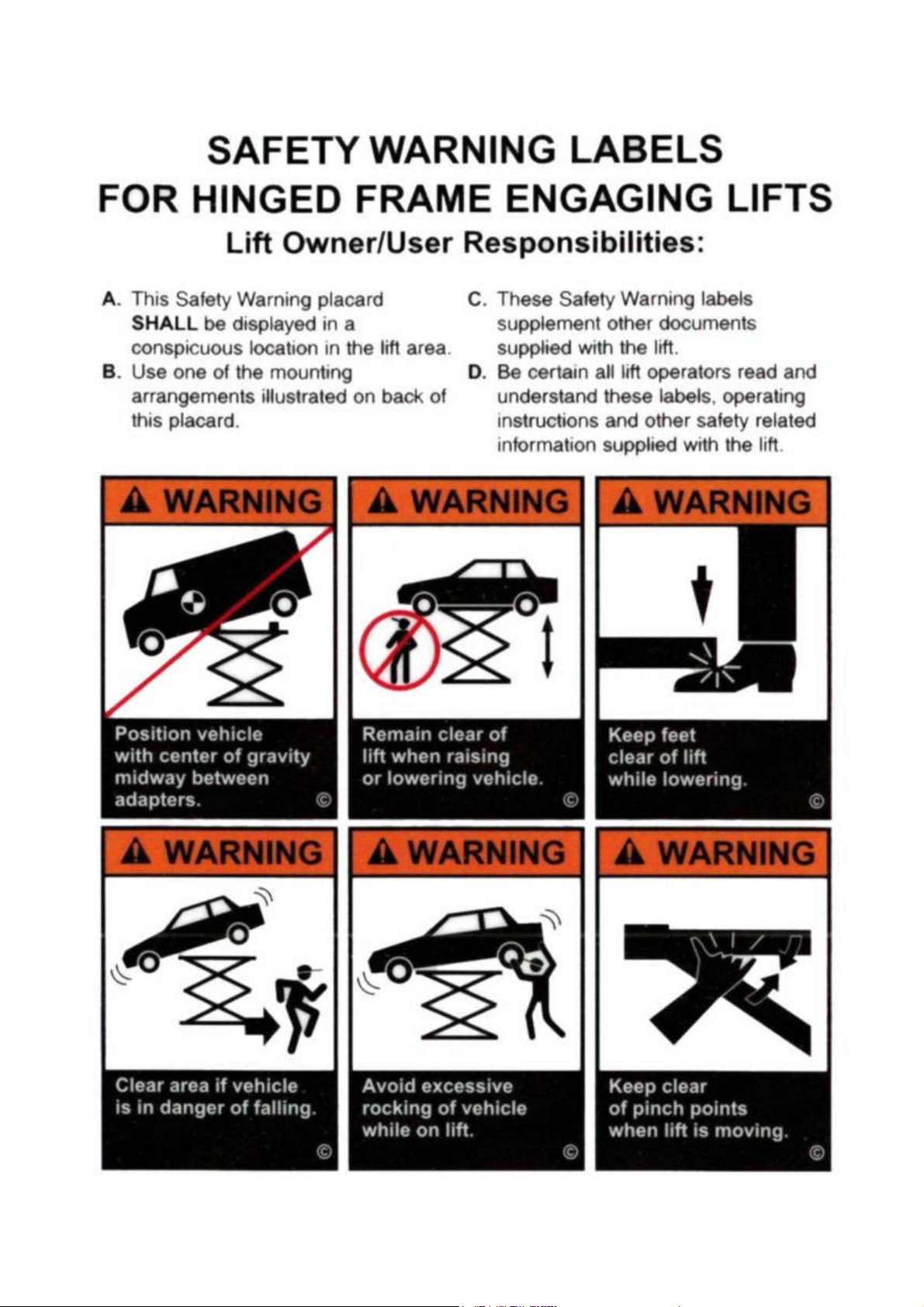
0.3 Indication of outstanding risks ............................................................................................................................................ 14
1. PURPOSE OF THE MACHINE ..........................................................................................17
1.1 Accessories ........................................................................................................................................................................ 18
2. PRE-INSTALLATION AND MOVEMENT ...........................................................................21
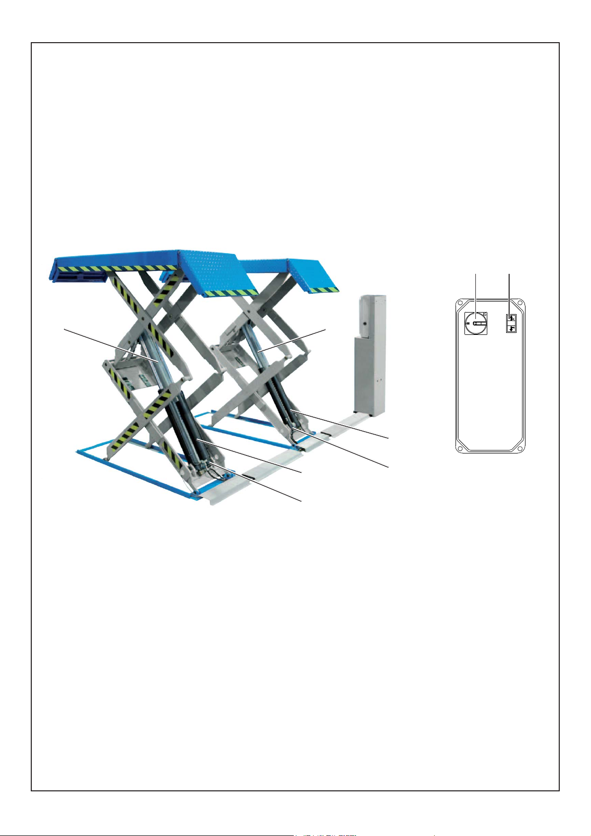
3. DESCRIPTION OF THE LIFT .............................................................................................22
3.1 Preparation for use ............................................................................................................................................................. 22
3.2 Main technical characteristics ............................................................................................................................................ 22
3.3 Controls .............................................................................................................................................................................. 22
3.4 Accessories on request ...................................................................................................................................................... 23
3.5 Available accessories ........................................................................................................................................................ 23
4. INSTALLATION ..................................................................................................................24
4.1 Checking the minimum requirements for the installation site ............................................................................................ 24
4.2 Preparing the installation area RAV540U .......................................................................................................................... 25
4.2.1 Special installation on request for RAV540U..................................................................................................................... 27
4.3 Preparing the installation area RAV540IU ........................................................................................................................ 29
4.4 Positioning the footboards and connecting the system in the standard position RAV540U ............................................ 30
4.5 Positioning the footboards and connecting the system in the standard position RAV540IU ............................................ 32
4.6 Connecting to the mains .................................................................................................................................................... 35
4.7 Connecting the power cable .............................................................................................................................................. 35
4.8 Compressed air connection ............................................................................................................................................... 37
4.9 Bleeding the air .................................................................................................................................................................. 39
4.10 Fastening the lift ................................................................................................................................................................. 41
4.11 Checking the safety switches ............................................................................................................................................. 41
4.12 Assembling ramps .............................................................................................................................................................. 43
4.13 Adjusting the levelling of the ramps ................................................................................................................................... 43
4.14 Fitting the ramp support - RAV540IU.................................................................................................................................. 45
4.15 Securing covers and control unit - RAV540U ................................................................................................................... 45
4.16 Operation of the lift ............................................................................................................................................................. 45
4.17 Operational test of lift .......................................................................................................................................................... 45
5. INSTRUCTIONS FOR USING THE LIFT ...........................................................................46
5.1 Improper use of the lift ........................................................................................................................................................ 46
5.2 Use of accessories ............................................................................................................................................................. 46
5.3 Training the machine-operating staff ................................................................................................................................. 46
5.4 Important checks to be made ............................................................................................................................................. 47
5.5 Description and function of commands .............................................................................................................................. 49
6. SAFETY ..............................................................................................................................51
6.1 Emergency procedures ...................................................................................................................................................... 51
6.2 Safety devices .................................................................................................................................................................... 51
7. MAINTENANCE .................................................................................................................52
7.1 Lift Lockout/Tagout Procedure ........................................................................................................................................... 52
7.2 Changing the oil in the central unit. ................................................................................................................................... 54
7.3 Cleaning the solenoid valves ............................................................................................................................................. 54
7.4 Cleaning the capacity regulator valve ............................................................................................................................... 54
7.5 Lubrication.......................................................................................................................................................................... 55
7.6 Manual procedure for platforms realignment ..................................................................................................................... 57
8. PROBLEMS ........................................................................................................................58
9. STORAGE...........................................................................................................................60
10. SCRAPPING.......................................................................................................................61
WIRING DIAGRAM ....................................................................................................................62
DIAGRAM OF HYDRAULIC SYSTEM.....................................................................................64
DIAGRAM OF PNEUMATIC SYSTEM ......................................................................................64
11. INSTALLATION AND PERIODIC INSPECTIONS..............................................................66
RESPONSIBILITY OF THE OWNER / EMPLOYER .................................................................67
12. IDENTIFICATION PLATE ...................................................................................................74

66 0579-M090-0
0. NORME GENERALI DI SICUREZZA
L'uso del sollevatore è consentito solo a personale appositamente addestrato e solo dopo avere letto e compreso il presente
manuale; l'operatore deve essere autorizzato da chi ricopre il ruolo di responsabile dell'impianto. Sono vietate manomissioni o
modifiche al sollevatore e ai dispositivi di sicurezza; nel caso in cui si verifichi quanto sopra scritto, il costruttore si ritiene sollevato
dai danni derivati. Seguire inoltre le seguenti indicazioni:
• Usare solo accessori e ricambi Ravaglioli originali.
• L'installazione deve essere fatta da personale autorizzato e qualificato.
• Assicurarsi che i tamponi di gomma siano posizionati correttamente sul sollevatore e prendano la vettura sotto allo chassis negli
appositi punti.
• Controllare che durante le fasi di salita e discesa non si verifichino condizioni di pericolo; in tal caso arrestare immediatamente
il sollevatore e rimuovere la causa che ha provocato l'emergenza.
• Prima di sollevare il veicolo assicurarsi che la ripartizione del carico sugli assi sia corretta per il sollevatore.
• Dopo il sollevamento posizionare l'interruttore sullo "0".
• Non si devono sollevare persone a bordo di autovetture, nè carichi pericolosi o esplosivi.
0. GENERAL SAFETY PRECAUTIONS
The lift must only be used by specially trained personnel and only after reading and understanding this manual; the operator must
be authorised by the system manager. The lift and safety devices must not be tampered with or modified in any way; if they are,
the manufacturer cannot accept any liability in the event of resulting damage. Always comply with the following:
• Only use original Ravaglioli accessories and spare parts.
• Installation must only be done by authorised and professional personnel.
• Make sure the rubber buffers are correctly positioned on the lift and support the vehicle under the chassis at the proper pickup
points.
• Make sure no hazardous situations arise during up/down movement; if they do, stop the lift immediately and remedy the cause
of the emergency.
• Before lifting the vehicle, make sure the way the load is distributed on the axles is correct for the lift.
• After lifting, position the switch on “0”.
• Do not lift people on board vehicles nor dangerous or explosives loads.

77
0579-M090-0
0.1 IMPORTANT SAFETY INSTRUCTIONS
When using your garage equipment, basic safety precautions should always be followed, including the following:
1. Read all instructions.
2. Care must be taken as burns can occur from touching hot parts.
3. Do not operate equipment with a damaged cord or if the equipment has been dropped or damaged - until it has been examined
by a qualified serviceman.
4. Do not let cord hang over edge of table, bench or counter or come in contact with hot manifolds or moving fan blades.
5. If an extension cord is necessary, a cord with a current rating equal to or more than that of the equipment should be used. Cords
rated for less current than the equipment may overheat. Care should be taken to arrange the cord so that it will not be tripped
over or pulled.
6. Always unplug equipment from electrical outlet when not in use. Never use the cord to pull the plug from the outlet. Grasp plug
and pull to disconnect.
7. Let equipment cool completely before putting away. Loop cord loosely around equipment when storing.
8. To reduce the risk of fire, do not operate equipment in the vicinity of open containers of flammable liquids (gasoline).
9. Adequate ventilation should be provided when working on operating internal combustion engines.
10. Keep hair, loose clothing, fingers, and all parts of body away from moving parts.
11. To reduce the risk of electric shock, do not use on wet surfaces or expose to rain.
12. Use only as described in this manual. Use only manufacturer's recommended attachments.
13. ALWAYS WEAR SAFETY GLASSES. Everyday eyeglasses only have impact resistant lenses, they are NOT safety glasses.
SAVE THESE INSTRUCTIONS
0.1 ISTRUZIONI DI SICUREZZA IMPORTANTI
Quando si utilizza l’apparecchiatura, devono sempre essere seguite le seguenti precauzioni di sicurezza:
1. Leggere tutte le istruzioni.
2. Fare attenzione a non toccare parti caldi che potrebbero causare ustioni in caso di contatto.
3. NON utilizzare l’apparecchiatura se il cavo di alimentazione è danneggiato o se l’apparecchiatura è caduta o danneggiata -
farla controllare prima di utilizzarla da un tecnico qualificato.
4. Non lasciare il cavo pendente dal bordo di un tavolo, supporto o banco, in modo da evitare che possa venire a contatto con
collettori caldi o pale di ventilatori in movimento.
5. Se è necessario l’uso di una prolunga, deve essere utilizzato un cavo con una potenza nominale pari o superiore a quello
dell’apparecchiatura. Cavi di potenza nominale inferiore rispetto all’apparecchiatura potrebbero surriscaldarsi. Prestare
attenzione a posizionare il cavo in modo che non sia tirato o si possa inciampare.
6. Scollegare sempre l’apparecchiatura dalla presa elettrica quando non utilizzata. Non usare il cavo per staccare la spina dalla
presa. Afferrare la spina e rimuoverla.
7. Lasciate raffreddare completamente l’apparecchiatura prima di riporla. Avvolgere il cavo senza stringere intorno all’apparec-
chiatura prima di riporla.
8. Per ridurre il rischio di incendio non utilizzare l’apparecchiatura in prossimità di contenitori aperti di liquidi infiammabili (benzina).
9. La ventilazione deve essere adeguata quando si lavora in interno con motori a scoppio.
10. Tenere i capelli, i vestiti, le dita e tutte le parti del corpo lontano da parti in movimento.
11. Per ridurre il rischio di scosse elettriche, non usare su superfici bagnate o esposte alla pioggia.
12. Usare solo come descritto in questo manuale. Utilizzare solo connessioni raccomandate dal produttore.
13. Indossare SEMPRE gli occhiali protettivi. Anche se gli occhiali da vista hanno lenti resistenti all impatto, ma NON sono occhiali
di sicurezza.
CONSERVARE QUESTE ISTRUZIONI

88 0579-M090-0
0.2 Dispositivi di sicurezza
Il sollevatore ha i seguenti dispositivi di sicurezza (con riferimento alla Fig.1):
1Interruttore generale lucchettabile con funzioni di arresto di emergenza.
2Comandi a uomo presente (immediato arresto dell'azione al rilascio del comando).
3Circuito idraulico con cilindri Master-Slave incrociati a garanzia della sincronizzazione delle pedane.
4Valvola di controllo discesa montata sui cilindri Master che rallenta la discesa del sollevatore in caso di rottura tubi in gomma.
5Dispositivo di appoggio meccanico ad inserimento automatico. Questo impedisce al sollevatore di scendere per più di 100 mm
qualora ci sia un qualunque difetto o perdita nel circuito idraulico di sollevamento.
ATTENZIONE:Quandoè premuto il pulsante di salita odidiscesavieneautomaticamente disinserito il dispositivo.
Per ripristinare la funzione di sicurezza rilasciare il comando.
0.2 Safety devices
The lift features the following safety devices (with reference to Fig.1):
1Padlockable main switch with emergency stop functions.
2Deadman device (immediate lift stop when control is released).
3Hydraulic system with crossed Master-Slave cylinders to grant platform synchronization.
4Lowering control valve fitted on the Master cylinders to slow lift lowering in case of rubber hose breaking.
5Automatically enganging mechanical support device. This prevents the lift decending more than 100 mm when there is a defect
or leak in the hydraulic circuit.
WARNING: When the up or down button is pressed, the device is automatically disarmed.
To reset the safety function release the command.

9
0579-M090-0
Fig.1
21
3
4
3
4
55


1414 0579-M090-0
0.3 Indicazione dei rischi residui
Il sollevatore è stato realizzato applicando le norme per rispondere ai requisiti delle direttive pertinenti.
L'analisi dei rischi è stata fatta ed i pericoli sono stati , per quanto possibile, eliminati.
Eventuali rischi residui sono evidenziati nel presente manuale e sulla macchina mediante pittogrammi adesivi (Fig.2).
Nel caso che questi pittogrammi si danneggiassero, è necessario sostituirli richiedendoli alla RAVAGLIOLI.
Il "SAFETY TIPS" (vedi pagina precedente) deve essere posizionato in una posizione sempre visibile dall'operatore.
0.3 Indication of outstanding risks
The lift has been manufactured in compliance with all standards required by applicable directives.
Risk analysis has been performed and all risks have, as far as possible, been eliminated.
Any outstanding risks are shown in this manual and on the machines by means of adhesive pictograms (Fig. 2).
In the event of these pictograms being damaged, they must be replaced with others available from RAVAGLIOLI.
"SAFETY TIPS" (see previous page) must be posted where they will be a constant reminder to the operator.
ADESIVI E DISPOSITIVI SEGNALAZIONE DI PERICOLO
TABLE FOR LABELS AND DANGER WARNING DEVICES
RIF. CODICE DESCRIZIONE DESCRIPTION
1 904265 Nastro zebrato Striped tape
2 999908660 Tabella livello olio Oil level table
3
999912530 Targhetta 220V 60Hz 1Ph 220V 60Hz 1Ph plate
999912510 Targhetta 220V 60Hz 3Ph 220V 60Hz 3Ph plate
999917990 Targhetta 575V 60Hz 3Ph 575V 60Hz 3Ph plate
4 99990758 Targhetta autoadesiva pericolo Self-sticking danger plate
5 999909700 Targhetta portata 9000 lbs Capacity 9000 lbs plate
6 999909850 Istruzioni d'uso Instructions use
7 999916440 Tabella marchio Mark plate
8
999919270 Targa matricola 220/60/1 220/60/1 Serial No plate
999919280 Targa matricola 220/60/3 220/60/3 Serial No plate
999199780 Targa matricola 575/60/3 575/60/3 Serial No plate
9 999919100 Targhetta Duty cycle 220/1/60 Duty cycle 220/1/60 label
999919110 Targhetta Duty cycle 220/3/60 — 575/3/60 Duty cycle 220/3/60 — 575/3/60 label
10 999918150 Targhetta CAUTION CAUTION label
11 999918160 Targhetta WARNING WARNING label
12 999918170 Targhetta GARAGE GARAGE label
13 999918200 Targhetta Fusibili di linea — 20A Line protection fuses label — 20A
999919730 Targhetta Fusibili di linea — 8A Line protection fuses label — 8A
14 999918210 Targh. Fusibili protez. Primario — 1A 250V Primary fuse protecion label — 1A 250V
999919740 Targh. Fusibili protez. Primario — 1A 600V Primary fuse protecion label — 1A 600V
15 999918220 Targh. Fusibili protez. Secondario Secondary fuse protec. label
16 999917880 Targh. Colleg. Cavo aliment. (3Ph) Power cable connecting label (3Ph)
999918000 Targh. Colleg. Cavo aliment. (1Ph) Power cable connecting label (1Ph)
17 599462 Targhetta simbolo Terra Grounding symbol label
18 999918460 Targhetta temperature Temperature label
19 999918640 Adesivo certificazione ETL ETL Certification label
20 999919010 Adesivo certificazione ALI ALI Certification label
21 999914450 Targhetta “Centralina senza olio” “Power unit without oil” label

1515
0579-M090-0
Fig.2
9101112
19
20
21
CENTRALINA SENZA OLIO
POWER UNIT WITHOUT OIL
HYDRAULIKAGGREGATE OHNE ÖL
UNITE HYDRAULIQUE SANS HUILE
CENTRAL HIDRAULICA SIN ACEITE
13
14
15
17
16
_______
____________________
____________________
____________________
____________________
____________________
_______
____________________
____________________
____________________
____________________
____________________
_______
____________________
____________________
____________________
____________________
____________________
_______
____________________
____________________
____________________
____________________
____________________
_______
____________________
____________________
____________________
____________________
____________________
18
43
........V .....Hz ...Ph
5
19
20
7
11
10
12
9
21
6
2
9000
lbs
18
8
1
1
1

1616 0579-M090-0
1
1
9000 lbs
1
1
G
Fig.3

1717
0579-M090-0
1. DESTINAZIONE D'USO
Il prodotto è destinato al sollevamento di autoveicoli; la portata è quella indicata nella targhetta matricola. È consentito il
sollevamento di autoveicoli rispondenti ai seguenti requisiti:
- peso non superiore alla portata del sollevatore
- ripartizione del carico sui punti di appoggio 1:1
- il veicolo deve essere posto in modo tale che il baricentro G dello stesso sia al centro delle pedane sia trasversalmente che
longitudinalmente (vedi Fig. 3).
-Il veicolo deve essere caricato solo attraverso i punti di appoggio previsti dal costruttore;
- per il sollevamento usare i tamponi in gomma forniti con il sollevatore. I tamponi non sono sovrapponibili;
-Per ripartizioni del carico diverse da quelle indicate, la portata del sollevatore viene ridotta. Pertanto, in questi casi o per
altri non contemplati dal presente manuale, sarà opportuno contattare il Costruttore.
- Per il posizionamento del veicolo consultare la guida " VEHICLE LIFTING POINTS " a corredo della documentazione del
sollevatore.
1. PURPOSE OF THE MACHINE
The product is designed for lifting motor vehicles; the capacity is indicated on the serial plate.
Vehicles corresponding to the following requirements may be lifted:
- weight not exceeding the capacity of the lift
- load division on the support points 1:1
- vehicle shall be positioned so that its centre of gravity G is at the centre of platforms both transversally and longitudinally (see
Fig. 3).
-vehicle must be lifted only through its hoisting points as specified by the Manufacturer;
- when lifting, use rubber pads supplied with the hoist. Pads cannot be put one on the other during vehicle hoisting;
-For load divisions other than the specified ones, lift capacity is reduced. Therefore, under these conditions or any other
condition not envisaged in this manual it will be necessary to contact the Manufacturer.
- For vehicle positioning see "VEHICLE LIFTING POINTS" guide equipped with your lift.

1818 0579-M090-0
1.1 Accessori
Con riferimento alla tabella 1 , è possibile individuare i tipi di accessori che possono essere utilizzati sui prodotti trattati in questo
manuale.
1.1 Accessories
Refer to table 1 for the complete range of accessories that can be fitted to the products on this manual.
TABELLA 1
TABLE 1
ACCESSORI IN DOTAZIONE - SUPPLIED ACCESSORIES FIGURA - DRAWING
TAMPONI H = 20 mm — 13/16” (Quantità 4 pezzi)
RUBBER PADS H = 20 mm — 13/16” (4 pcs)
TAMPONI H = 40 mm — 1 9/16” (Quantità 4 pezzi)
RUBBER PADS H = 40 mm — 1 9/16” (4 pcs)
ACCESSORI A RICHIESTA - ACCESSORIES ON REQUEST FIGURA - DRAWING
TAMPONI H = 120 mm — 4 3/4” (Quantità 4 pezzi)
RUBBER PADS H = 120 mm — 4 3/4” (4 pcs)

1919
0579-M090-0
RAV540U RAV540IU
CARATTERISTICHE TECNICHE
TECHNICAL SPECIFICATIONS 220V 60Hz 1Ph 220V 60Hz 3Ph 575V 60Hz 3Ph
Portata (lbs)
Capacity (lbs) 9000 (4082 kg)
Motore (kW)
Motor
(
kW
)
2,6 3 3
Tempo salita (“)
Lifting time (“) 75 37 37
Tempo discesa (“)
Descending time (“) 38 38 38
Peso (lbs)
Wei
g
ht
(
lbs
)
1874 (850 kg)
Emissione sonora dB (A)
Sound emission dB (A) < 70
Min. bay size 15’ 6” x 22’ (4724 x 6706 mm)
Pressione aria (psi)
Air
p
ressure
(p
si
)
Min. 87 - Max. 145 (Min.6 - Max.10 Bar)
Pressione olio (psi)
Oil pressure (psi) 4496 (310 Bar)
6' 9 7/8"
(9 7/16")(4' 9 3/32")
(1' 3 11/32")
(6' 6 3/4")
(6' 9 3/32")
(5 5/16")
2' 13/32"2' 13/32" 2' 7 3/32"
(10")
3' 3 3/8"
(11 1/16")
6' 9 7/8"
(9 7/16")(4' 9 3/32")
(1' 3 11/32")
(6' 1 7/32")
(4' 4 5/32")
(6' 11 1/16")
(5 1/2")
2' 13/32"2' 13/32" 2' 7 3/32"3' 3 3/8"
(11 1/16")
(10")
(4' 4 5/32")
2' 2 9/16"2' 5 29/32"2' 2 9/16"
(19/32")(19/32")
(13/32")
(1 3/16")
(7 7/8")
(2 3/4")

2020 0579-M090-0
Fig. 4
Fig. 5
CASSA
LIFT
(216 x 69 x 71,5 cm)
(7' 1" x 2' 3 1/8" x 2' 4 1/8")
1
2
3
45
6
7
8
9
10
11
This manual suits for next models
1
Table of contents
Other Ravaglioli Scissor Lift manuals
Popular Scissor Lift manuals by other brands

Airo
Airo SF series Use and maintenance manual

WERTHER INTERNATIONAL
WERTHER INTERNATIONAL STRATOS S39 Instruction and maintenance manual

Celexon
Celexon PL1000 Plus installation manual

Haulotte Group
Haulotte Group OPTIMUM 6 Operating and maintenance instructions

Mec
Mec 1330SE Service and parts manual

GMG
GMG 1930-ED Operator's manual

WERTHER INTERNATIONAL
WERTHER INTERNATIONAL RPK25/B Instruction and maintenance manual

HanseLifter
HanseLifter SPA Series operating manual

MAHA
MAHA Twin Series Operation manual

Bosch
Bosch VLS 3132 H Original instructions

JLG
JLG 1932RS/6RS Operation and safety manual

Bend-Pak
Bend-Pak SP-7XE Installation and operation manual