Rave RMC-66A User manual

Installation Manual
RMC-66A
6 Zone 6 Source Audio Matrix with Integrated Amplifier
OGY.COM
WWW.RAVETECHNOLOGY.COM

2
OGY.COM
WWW.RAVETECHNOLOGY.COM

3
OGY.COM
WWW.RAVETECHNOLOGY.COM
Note:
RMC-66K (Optional) Accessory Kit Includes:
•6 Wall Plate Keypads
•1 Wall Plate Keypad Hub
•1 IR Remote Control
•1 Expansion Cable
RMC-66A Matrix Controller Amplifier
Package Contents
INTRODUCTION
The RMC-66A is a functional, easy-to-install, highly compatible, expandable, and user-friendly audio
distribution system. The RMC-66A provides 6 zones stereo or bridged speaker outputs power by class
D integrated amplifier. With optional expansion cables the RMC-66A is expandable up to 18 zones.
This system can be controlled with (optional) Keypads, RS232, IR or with the iOS and Android APP.
Enjoy the quality and reliability of your new RAVE Technology RMC-66A.
FEATURES
•6 Source 6 Zone Audio Matrix with Integrated Amplifier
•Multi-Room Audio Control System Expandable to 18 Zones
•APP Control with Wi-Fi or Ethernet Network Connection
•High Efficiency Class D Amplification
•Stereo or Bridged (mono) Speaker Outputs
•Optional Keypads and IR Remote
•110V or 220V Selectable Power
•RS232 Communication Port
•12V Trigger Inputs and Outputs
•Source 1 Priority PA Function with Trigger Input
•Built In IR Emitters Outputs
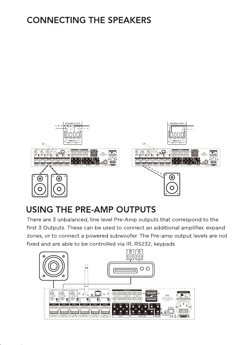
•Preamp Outputs Zone 1-3

5
1. Power ON/OFF Switch
2. Zone Status LED
(White: ON - Blue: Standby - Blue/White: Mute)
PRODUCT FEATURES
OGY.COM
WWW.RAVETECHNOLOGY.COM
1. Stereo RCA line level preamp outputs zones 1-3
2. Mode Switch: Stereo or Bridge (mono)
3. Speaker Outputs: Removable terminal block connectors
4. Integrated LAN and Wi-Fi Network
5. 12V Trigger outputs
6. Stereo RCA source inputs (Source 1 priority with PA trigger input)
7. IR Emitter outputs
8. PA trigger input-Mute trigger input-Control trigger output
9. Expansion input and output ports
10. RS232 Communications port
11. Voltage selector switch
12. AC Power connector
13. Keypad Hub RJ45 connector
14. Auto gain control (AGC) on/off switch
15. Unit ID selector switch (Master-Slave1-Slave2)

6
The optional Infrared remote provides zone control through the (IR) receiver
located in the center of the keypad. All keypad functions can be accessed with the
remote. An additional mute button to temporarily mute audio in the zone. The
keypad LED display will flash indicating the mute status. Press the mute button
again to return to un-mute the zone.
OGY.COM
WWW.RAVETECHNOLOGY.COM
KEYPAD AND IR REMOTE FEATURES
The optional keypads can control zone power on/off, volume up/down, selection of
sources 1-6, zone treble, zone bass, zone un-mute and zone standby. The keypads
have Infrared receivers which allows control with optional IR hand held remote. The
IR system can also send IR commands to the IR output jacks of the RMC-66A for
control of your source components.

8
Connect audio sources to the RMC-66A using the 6 stereo RCA inputs on the
rear panel. Input 1 can be used as priority over all inputs. When 12VDC is
applied (3.5mm tip+ sleeve -) to the PA-IN jack, source 1 will be sent to all
zones. This can be used for party mode or paging.
INSTALLATION
OGY.COM
WWW.RAVETECHNOLOGY.COM
CONNECTIONS

9
and APP.
STEREO MODE BRIDGED MODE
The RMC-66A is capable of driving 4-8 ohm speaker loads in stereo mode and 8ohm loads in
bridge (mono) mode. Improper speaker installation can damage the amplifiers and void the
warranty. Use good quality 12-14awg stranded copper speaker wire.
The speaker output terminal block connectors are removable. Remove the terminal block connector
and make sure that all connections are open by turning each set screw counter clockwise. This
insures that the speaker wire opening is completely open. Trim approx 1/4” of insulation from the
speaker wire and twist the copper ends. Insert the speaker wires into the connector and tighten the
set screws. Repeat for the remaining zones.
BRIDGE MODE:
Setting the amplifier mode switch to BRIDGE mode will combine the LEFT and RIGHT signals and
power into one amplifier. The LEFT and RIGHT input signals will be summed to mono. The
minimum speaker impedance in bridge mode is 8ohms.
OGY.COM
WWW.RAVETECHNOLOGY.COM

The RMC-66A has optional POE enabled keypads. This allows for source control from each
specific zone as well as IR routing to the appropriate source devices once selected.
The RMC-66K (Optional Accessory Kit) also comes with a hub that allows for all 6-keypads to
be connected to the amp via Cat5e/6.
10
ZONE-1
ON ON OFF
1 2 3
ZONE-2
ON ONOFF
1 2 3
ZONE-3
ON OFFOFF
1 2 3
ZONE-4
ONONOFF
1 2 3
ZONE-5
ON OFFOFF
1 2 3
ZONE-6
ONOFFOFF
1 2 3
OGY.COM
WWW.RAVETECHNOLOGY.COM

11
FRONT BACK
Expansion Port
OGY.COM
WWW.RAVETECHNOLOGY.COM
CONNECTING THE KEYPAD HUB
Each source has a corresponding Infrared (IR) emitter output. These outputs are
use to control the connected source components remotely through the IR system.
Connect an IR emitter to the output jack and then connect the flasher to the IR
receiver window of the device. Now you can use an IR remote to control your
source through the keypads.
Input Source 2-DVD
IR Output from Source 2
Power
IR Signal
Grounding
IR +
IR -
IR EMITTERS

12
There is also a master control 12VDC trigger output which sends 12VDC to the
CONTROL OUT jack when any zone is powered ON. The 12VDC CONTROL OUT
signal is disengaged when all zones are powered OFF.
PA- IN- Insert 12VDC and Input 1 takes priority over all other inputs and
broadcasts to all 6 zones.
MUTE - IN- Insert 12VDC and all zones will be muted.
WIRING: 3.5mm Mono Plug (Tip + / Sleeve -)
Motorized screen External amplifier
Trigger Inputs and Outputs
OGY.COM
WWW.RAVETECHNOLOGY.COM

14
Master
SLAVE 1
SLAVE 2
EXPANSION ZONES
The RMC-66A allows 6 sources to be distributed to 18 zones on 3 different units using the
optional expansion cable to connect between units.
To do this each unit needs to be addressed according using the MASTER/SLAVE switch.
There are 3 positions for this, Master, Slave 1, and Slave 2 which identify each unit.
All source audio information - All RS232 control data - All MCU communication from the master
and slave units will be shared through the expansion cable.
Each RMC-66A unit must be connected to the network for APP control.
NOTE: The MASTER unit IR outputs will function as normal however the IR outputs from SLAVE
1 & 2 will not pass through the MASTER IR outputs. IR flashers from SLAVE 1 & 2 will need to
added for IR control.
OGY.COM
WWW.RAVETECHNOLOGY.COM

LAN NETWORK CONNECTION
There is a RJ-45 Ethernet jack on the rear panel of this amplifier for the connecting to the
network. Please use a good quality Cat5e/5 cable, and follow the diagram below.
Connect the RMC-66A network LAN port on the rear panel to the LAN port of the Wi-Fi
router.
When controlling via Network connection, please make sure the ETHERNET/RS232
switch is set at ETHERNET position. If you are using the RS232 port for control please
set the switch to the RS232 position.
15
Router
OR
PC
PC
OGY.COM
WWW.RAVETECHNOLOGY.COM
NOTE: The network router will automatically set the IP address DHCP default ON.
Please check the local router configuration page for the RMC-66A IP information.

1. Select "Wi-Fi(client)-serial" from the NetMode menu options.
2. Press SCAN button in the SSID menu.
3. Select the wireless network you would like to connect and press APPLY.
4. Enter the password for the wireless network and press APPLY.
5. Visit the configuration web page of the local network of router
to find the IP address information for the RMC-66A.
Wi-Fi NETWORK CONNECTION
Power on the RMC-66A in range of the Wi-Fi network.
Using a PC, Smart phone or Tablet (PC is recommended), search the Wi-Fi and connect to
the RMC-66A.
SSID: HLINK
Password: 12345678
Go to the (http://192.168.16.254) configuration web page and login
User name: admin
Password: admin
OGY.COM
WWW.RAVETECHNOLOGY.COM

Each source has a corresponding Infrared (IR) emitter output. These outputs
are use to control the connected source components remotely through the IR
system. Connect an IR emitter to the output jack and then connect the flasher
to the IR receiver window of the device. Now you can use an IR remote to
control your source through the keypads.
13
Input Source 2-DVD
IR Output from Source 2
Power
IR Signal
Grounding
IR +
IR -
OGY.COM
WWW.RAVETECHNOLOGY.COM

RMC-66A RS-232 CONTROL CODES
(Baud Rate: 9600,8,N,1 , DB9 Connector Pin out, Tx, Rx, GND)
'CR':Carriage Return (0x0D)
Not case sensitive
Control Command Structure <xxPPuu'CR'
Reply Control Command Structure >xxPPuu'CR'
xx: Represent control command code
10 :All zones of host computer 1
20 :All zones of host computer 2
30 :All zones of host computer3
11 : Zone1 of host computer 1
12 : Zone2 of host computer 1
13 : Zone3 of host computer 1
...............
PP: Represent Control action code
PR:Power control
PR00:Power off
PR01:Power on
MU:Mute control
MU00:Mute off
MU01:Mute on
DT:Do Not Disturb control
DT00:DT control off
DT01:DT control on
VO:Volume control
VO(00-38):Volume control
TR:Treble control
TR(00-14):Treble control
BS:Bass control
BS(00-14):Bass control
BL:Balance control
BL(00-20):Balance control
CH:Source Channel control
CH(01-06):Source control
Ask command structure(1) ?xx'CR' xx:
Represent control command code 10 :All
Zones of host computer 1
20 :All Zones of host computer 2
21
OGY.COM
WWW.RAVETECHNOLOGY.COM

30 :All Zones of host computer 3
11 :Zone1 of host computer1
12 :Zone2 of host computer1
13 : Zone3 of host computer1
21 : Zone1 of host computer2
22 : Zone2 of host computer2
23 : Zone3 of host computer2
...............
Reply Command: >xxaabbccddeeffgghhiijj'CR'
aa:PA Control status
bb:Power Control status ([5]:Backup Zone Power Status (only on zone) cc:Mute
Control status
dd:DT Control status
ee:Volume Control status
ff:Treble Control status
gg:Bass Control status
hh:Balance Control status
ii:Source Control status
jj:The connection status of line control(00:unconnected 01:connected) Ask
command structure (2) ?xxPP'CR'
xx: Control Command Structure
10 :All Zones of host computer 1
20 :All Zones of host computer 2
30 :All Zones of host computer 3
11 : Zone1 of host computer 1
12 : Zone2 of host computer 1
13 : Zone3 of host computer 1
14 : Zone4 of host computer 1
15 : Zone5 of host computer 1
16 : Zone6 of host computer 1
...............
PP: Represent Control action code
PA:PA Control
PR:Power Control
MU:Mute Control
DT:DT Control
VO:Volume Control
TR:Treble Control
BS:Bass Control
22
OGY.COM
WWW.RAVETECHNOLOGY.COM

Zone
1~6
1~6
1~6
1~6
1~6
1~6
1~6
BL:Balance Control
CH:Source Control
LS: The connection status of line control
Reply command: >xxPPuu'CR'
Enter1<********'CR' Change Source 1 display name;********It must be 8 effective
ASCII code
Enter2<********'CR' Change Source 2 display name
Enter 3<********'CR' Change Source 3 display name
Enter 4<********'CR' Change Source 4 display name
Enter 5<********'CR' Change Source 5 display name
Enter 6<********'CR' Change Source 6 display name
Enter M<********'CR' Change display name of connect control when it starts
Enter <9600'CR' Change RS232 to rate 9600
Enter <19200'CR' Change RS232 to rate 19200
Enter <38400'CR' Change RS232 to rate 38400
Enter <57600'CR' Change RS232 to rate 57600
Enter <115200'CR' Change RS232 to rate 115200
Enter <230400'CR' Change RS232 to rate 230400
When unplugging and re-plugging the AC power cord, the
Baud speed rate will return to 9600.
REPRESENT OF CONTROL ACTION CODE
Symbol
<
<
<
<
<
<
<
Controlactioncode
PR(POWER)
MU(MUTE)
CH(SOURCE)
VO(VOLUME)
TR(TREBLE)
BS(BASS)
BL(BALANCE)
ControlRange
(00-01)
(00-01)
(01-06)
(00-38)
(00-14)
(00-14)
(00-20)
Master、Slave1、Slave2
1、2、3
1、2、3
1、2、3
1、2、3
1、2、3
1、2、3
1、2、3
23
OGY.COM
WWW.RAVETECHNOLOGY.COM

<11PR01
<21PR00
<16MU01
<35MU00
<11CH01
<16CH06
<11VO00
<16VO38
<11TR00
<11TR07
<11TR14
<16BS00
<16BS07
<13BS14
<11BL00
<11BL10
<11BL20
?20
Zone1ON
Salve1/Zone1OFF
Zone6MuteON
Salve2/Zone5MuteOFF
Zone1Source01
Zone6Source06
Zone1Volume00
Zone6Volume38
Zone1Treble(-7)
Zone1Treble(0)
Zone1Treble(7)
Zone6Bass(-7)
Zone6Bass(0)
Zone3Bass(7)
Zone1Balance(atLeftCH)
Zone1Balance(atMiddle)
Zone1Balance(atRightCH)
InquirySlave1AllZoneStatus
<10PR01
<10PR00
<10MU01
<10MU00
<10CH01
<10CH06
<10VO00
<10VO38
<10TR00
<10TR07
<10TR14
<10BS00
<10BS07
<10BS14
<10BL00
<10BL10
<10BL20
?10
INQUIRY COMMAND STRUCTURE
EXAMPLES OF RS-232 COMMAND CODE
AllZoneON
AllZoneOFF
AllZoneMuteON
AllZoneMuteOFF
AllZoneSource01
AllZoneSource06
AllZoneVolume00
AllZoneVolume38
AllZoneTreble(-7)
AllZoneTreble(0)
AllZoneTreble(7)
AllZoneBass(-7)
AllZoneBass(0)
AllZoneBass(7)
AllZoneBalance(atLeftCH)
AllZoneBalance(atMiddle)
AllZoneBalance(atRightCH)
InquiryMasterAllZoneStatus
Symbol
?
InquiryMasterAllZoneStatus
InquirySlave1AllZoneStatus
InquirySlave2AllZoneStatus
?10
?20
?30
Master、Salve1、Salve2
1、2、3
Zone
1~6
24
OGY.COM
WWW.RAVETECHNOLOGY.COM

REPLY COMMAND
>xxaabbccddeeffgghhiijj
>1100000000200707100100
xx:Unit/Zone
aa:PAINStatus
bb:PowerStatus
cc:MuteStatus
dd:DTStatus
ee:VolumeStatus
ff:TrebleStatus
gg:BassStatus
hh:BalanceStatus
ii:SourceStatus
jj:KeypadConnectionStatus(00:Unconnected,01:Connected)
25
OGY.COM
WWW.RAVETECHNOLOGY.COM
OGY.COM
WWW.RAVETECHNOLOGY.COM

Contact Information:
Rave Technology
4100 East Baldwin Road
Holly, Michigan, 48442 USA
Tel: 866-303-2629
www.ravetechnology.com
Warranty:
Rave Technology products are warranted to be free
from defects in workmanship and materials for a
period of Five (5) years from the date of purchase
without charge for parts or labor.
This warranty does not apply to units that have been
subject to misuse, abuse, neglect or improper
installation, and does not apply to repairs or
alterations made by unauthorized personnel.
This warranty specifically excludes responsibility for
consequential damage.
Retention of your original bill of sale is required to
obtain service under the terms of this warranty.
© 2020 Rave Technology. All rights reserved.
All trademarks are the property of their respective
owners. Specifications are subject to change without
notice.
SPECS AND WARRANTY
OGY.COM
WWW.RAVETECHNOLOGY.COM
Table of contents
Other Rave Amplifier manuals