Rave RMC-66P User manual

3
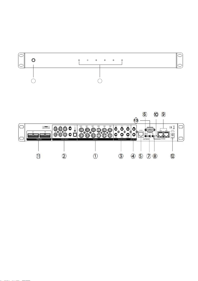
•6 Source Inputs: 3 Stereo RCA, 2 Stereo 3.5mm and 1 Optical Connector
•6 Zone Stereo RCA outputs
•APP Control iOS and Android
•RJ45 Ethernet Connection Ports
•RS-232 Communication Port
•Built-in IR Emitters
•12V DC Trigger Outputs
•Expandable up to 18 Zones
•Zone status LED
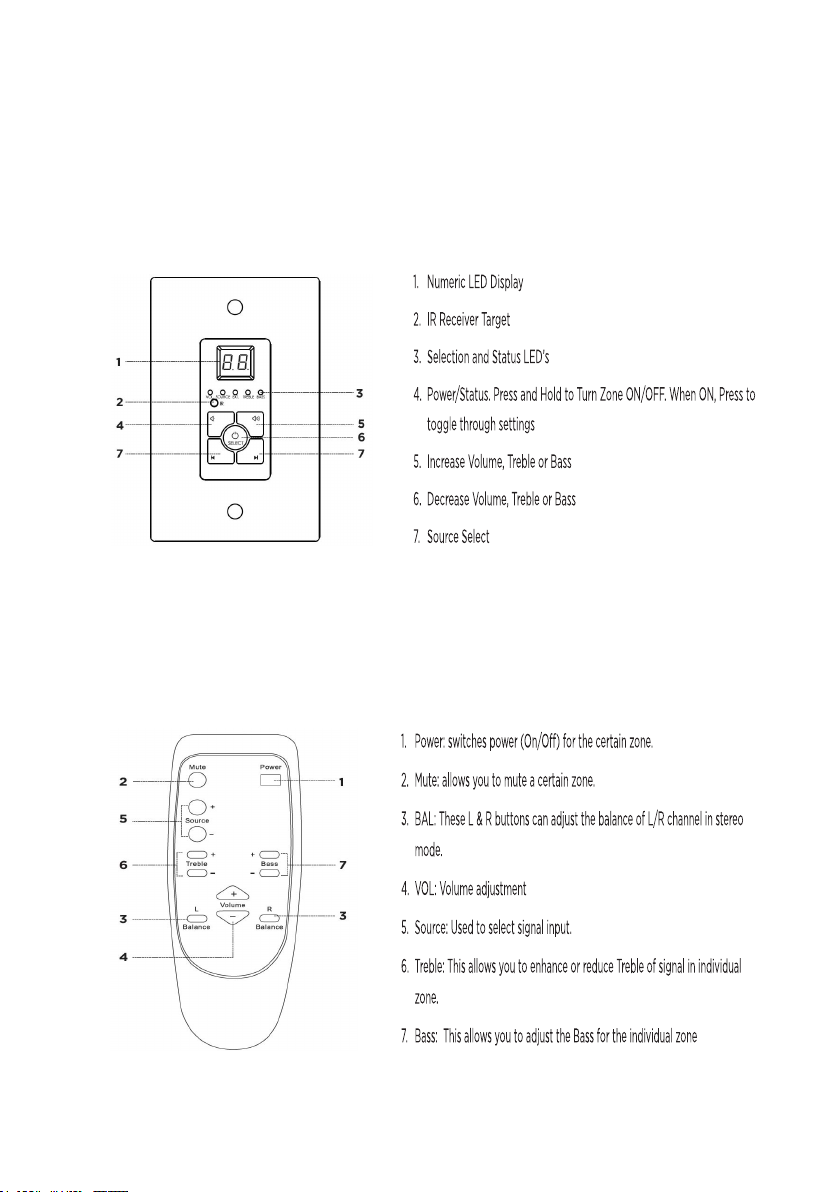
•Optional Keypad and IR Remote Control
WWW.RAVETECHNOLOGY.COM
INTRODUCTION
The RMC-66P is a functional, easy-to-install, highly compatible, expandable, and user-friendly
audio distribution system. The RMC-66P provides 6 Source inputs and 6 zones with stereo RCA
preamp outputs. The RMC-66P combined with the optimal power amplifier creates a customized
audio distribution system. With optional expansion cables the RMC-66P is expandable up to 18
zones. This system can be controlled with (optional) keypads, RS232, IR or with the iOS and
Android APP. Enjoy the quality and reliability of your new RAVE Technology RMC-66P.
FEATURES
PACKAGE CONTENT
•RMC-66P Matrix Controller Preamplifier
•Rack Mounting Ears 2 (Installed)
•External Power Supply
•User Manual
•1 IR Remote Control
•1 Expansion Cable
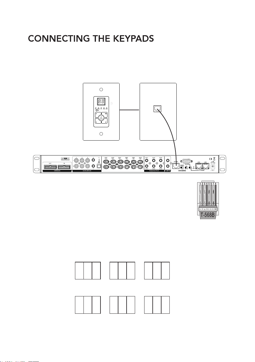
•1 Wall Plate Keypad Hub
•6 Wall Plate Keypads
Note:
RMC-66K (Optional) Accessory Kit

5
POWER
ZONE 1 ZONE 2 ZONE 3 ZONE 4 ZONE 5 ZONE 6
PRODUCT FEATURES
1. PRE-AMP OUTPUTS
2. SOURCE INPUTS
3. 12V TRIGGER OUTPUTS
4. IR EMITTER OUTPUTS
5. KEYPAD HUB CONNECTION
6. UNIT ID SWITCH (Master-Slave1-Slave2)
7. AUTO GAIN CONTROL
8. COMMUNICATION (Ethernet/RS232)
9. ETHERNET PORTS
10. NETWORK RESET (Factory default)
11. EXPANSION INPUT/OUTPUT
12. POWER SUPPLY INPUT JACK
13. RS232 COMMUNICATION PORT
1. POWER ON/OFF SWITCH
2. LED ZONE STATUS (Blue: Standby-White: ON-Blue/White: Mute)
1
2
WWW.RAVETECHNOLOGY.COM

6
The optional Infrared remote provides zone control of the MRC-66P through the
(IR) receiver located in the center of the keypad. All keypad functions can be
accessed with the remote. An additional mute button to temporarily mute audio in
the zone. The keypad LED display will flash indicating the mute status. Press the
mute button again to return to un-mute the zone.
OGY.COM
WWW.RAVETECHNOLOGY.COM
KEYPAD AND IR REMOTE FEATURES
The optional keypads can control zone power on/off, volume up/down, selection of
sources 1-6, zone treble, zone bass, zone un-mute and zone standby. The
keypads have Infrared receivers which allows control of source devices and the
RMC-66P with the optional IR remote. The IR system can also send IR commands
to the IR output jacks of the RMC-66P for control of your source components.

The RMC-66P has optional POE enabled keypads. This allows for source control
from each specific zone as well as IR routing to the appropriate source devices once
selected. The RMC-66K (Optional Accessory Kit) also comes with a hub that allows
for all 6-keypads to be connected to the RMC-66P via Cat5e/6.
9
ZONE-1
ON ON OFF
1 2 3
ZONE-2
ON ONOFF
1 2 3
ZONE-3
ON OFFOFF
1 2 3
ZONE-4
ONONOFF
1 2 3
ZONE-5
ON OFFOFF
1 2 3
ZONE-6
ONOFFOFF
1 2 3
WWW.RAVETECHNOLOGY.COM
Without the power being connected, make the keypad hub
connection from the from the RJ45 port on the back of the
RMC-66Pand the front RJ45 port of the hub. 568B termination
standard is recommended.
Next you will need to ensure that each keypad has the proper zone ID assigned.
Please refer to the chart below or the rear panel of the keypad for the dip switch
settings for each zone ID. Set the keypad ID for the zone you want to control.

10
Source 2-DVD
IR Emitter from
Source 2 port
Power
IR Signal
Grounding
IR +
IR -
IR EMITTERS
There are 2 Infrared (IR) emitter outputs on the RMC-66P. These outputs are used to control the
connected source components remotely through the RMC-66P keypad IR receiver.
For example, connect the flasher to the IR output and receiver window of the connected source.
Now you can use your IR remote to control your source through all zones with keypads.
WWW.RAVETECHNOLOGY.COM
CONNECTING THE KEYPAD HUB
FRONT BACK
Expansion Port

11
1. First each unit needs to be addressed using the MASTER/SLAVE switch.
There are 3 positions for this, Master, Slave 1, and Slave 2 to identify each unit.
2. Connect the expansion OUTPUT of the MASTER unit to the INPUT of Slave1
3. Connect the OUTPUT of SLAVE 1 to the INPUT of SLAVE 2.
WWW.RAVETECHNOLOGY.COM
All source audio information - All RS232 control data - All MCU communication from the
master and slave units will be shared through the expansion cable. Each RMC-66P unit
must be connected to the network for APP control.
NOTE: The MASTER unit IR outputs will function as normal however the IR outputs from
SLAVE1 and SLAVE2 will not pass through the MASTER IR outputs.
IR flashers from SLAVE1 and SLAVE2 zones will need to added to source for IR control
of source devices connected to the MASTER unit.
TRIGGER OUTPUTS
There are 6 trigger outputs corresponding to each zone. When a zone
is powered ON the zone sends 12VDC to the trigger output jack. When
the zone is powered OFF the signal is disengaged. Triggers can be
used to power peripheral equipment ON/OFF with the zones.
ZONE EXPANSION

LAN NETWORK CONNECTION
There are 2 Ethernet ports on the rear panel of the RMC-66P for the connecting to the
network and connecting additional RMC-66P or other network devices.
Connect the RMC-66P network LAN port to the LAN port of the Wi-Fi Router.
Connect the 2nd port labeled "to device" to a network device. The to device port
operates like a network switch when LAN port is connected to a network.
Please use a good quality Cat5e/5 cable, and follow the diagram below.
15
OGY.COM
WWW.RAVETECHNOLOGY.COM
When controlling via Network connection, please make sure the ETHERNET/RS232 switch is set at
ETHERNET position. If you are using the RS232 port for control please set the switch to the RS232
position. Connect the RMC-66P network LAN port to the LAN port of the Wi-Fi Router.
NOTE: The network router will automatically set the IP address DHCP default ON.
Please check the local router configuration page for the IP information.

RMC-66P RS-232 CONTROL CODES
(Baud Rate: 9600,8,N,1 , DB9 Connector Pin out, Tx, Rx, GND)
'CR':Carriage Return (0x0D)
Not case sensitive
Control Command Structure <xxPPuu'CR'
Reply Control Command Structure >xxPPuu'CR'
xx: Represent control command code
10 :All zones of host computer 1
20 :All zones of host computer 2
30 :All zones of host computer3
11 : Zone1 of host computer 1
12 : Zone2 of host computer 1
13 : Zone3 of host computer 1
...............
PP: Represent Control action code
PR:Power control
PR00:Power off
PR01:Power on
MU:Mute control
MU00:Mute off
MU01:Mute on
DT:Do Not Disturb control
DT00:DT control off
DT01:DT control on
VO:Volume control
VO(00-38):Volume control
TR:Treble control
TR(00-14):Treble control
BS:Bass control
BS(00-14):Bass control
BL:Balance control
BL(00-20):Balance control
CH:Source Channel control
CH(01-06):Source control
Ask command structure(1) ?xx'CR'
xx: Represent control command code
10 :All Zones of host computer 1
20 :All Zones of host computer 2
19
WWW.RAVETECHNOLOGY.COM

30 :All Zones of host computer 3
11 :Zone1 of host computer1
12 :Zone2 of host computer1
13 : Zone3 of host computer1
21 : Zone1 of host computer2
22 : Zone2 of host computer2
23 : Zone3 of host computer2
...............
Reply Command: >xxaabbccddeeffgghhiijj'CR'
aa:PA Control status
bb:Power Control status ([5]:Backup Zone Power Status (only on zone)
cc:Mute Control status
dd:DT Control status
ee:Volume Control status
ff:Treble Control status
gg:Bass Control status
hh:Balance Control status
ii:Source Control status
jj:The connection status of line control(00:unconnected 01:connected)
Ask command structure (2) ?xxPP'CR'
xx: Control Command Structure
10 :All Zones of host computer 1
20 :All Zones of host computer 2
30 :All Zones of host computer 3
11 : Zone1 of host computer 1
12 : Zone2 of host computer 1
13 : Zone3 of host computer 1
14 : Zone4 of host computer 1
15 : Zone5 of host computer 1
16 : Zone6 of host computer 1
...............
PP: Represent Control action code
PA:PA Control
PR:Power Control
MU:Mute Control
DT:DT Control
VO:Volume Control
TR:Treble Control
BS:Bass Control
20
WWW.RAVETECHNOLOGY.COM

Zone
1~6
1~6
1~6
1~6
1~6
1~6
1~6
BL:Balance Control
CH:Source Control
LS: The connection status of line control
Reply command: >xxPPuu'CR'
Enter1<********'CR' Change Source 1 display name;********It must be 8 effective
ASCII code
Enter2<********'CR' Change Source 2 display name
Enter 3<********'CR' Change Source 3 display name
Enter 4<********'CR' Change Source 4 display name
Enter 5<********'CR' Change Source 5 display name
Enter 6<********'CR' Change Source 6 display name
Enter M<********'CR' Change display name of connect control when it starts
Enter <9600'CR' Change RS232 to rate 9600
Enter <19200'CR' Change RS232 to rate 19200
Enter <38400'CR' Change RS232 to rate 38400
Enter <57600'CR' Change RS232 to rate 57600
Enter <115200'CR' Change RS232 to rate 115200
Enter <230400'CR' Change RS232 to rate 230400
When unplugging and re-plugging the AC power cord, the
Baud speed rate will return to 9600.
REPRESENT OF CONTROL ACTION CODE
Symbol
<
<
<
<
<
<
<
Controlactioncode
PR(POWER)
MU(MUTE)
CH(SOURCE)
VO(VOLUME)
TR(TREBLE)
BS(BASS)
BL(BALANCE)
ControlRange
(00-01)
(00-01)
(01-06)
(00-38)
(00-14)
(00-14)
(00-20)
Master、Slave1、Slave2
1、2、3
1、2、3
1、2、3
1、2、3
1、2、3
1、2、3
1、2、3
21
WWW.RAVETECHNOLOGY.COM

<11PR01
<21PR00
<16MU01
<35MU00
<11CH01
<16CH06
<11VO00
<16VO38
<11TR00
<11TR07
<11TR14
<16BS00
<16BS07
<13BS14
<11BL00
<11BL10
<11BL20
?20
Zone1ON
Salve1/Zone1OFF
Zone6MuteON
Salve2/Zone5MuteOFF
Zone1Source01
Zone6Source06
Zone1Volume00
Zone6Volume38
Zone1Treble(-7)
Zone1Treble(0)
Zone1Treble(7)
Zone6Bass(-7)
Zone6Bass(0)
Zone3Bass(7)
Zone1Balance(atLeftCH)
Zone1Balance(atMiddle)
Zone1Balance(atRightCH)
InquirySlave1AllZoneStatus
<10PR01
<10PR00
<10MU01
<10MU00
<10CH01
<10CH06
<10VO00
<10VO38
<10TR00
<10TR07
<10TR14
<10BS00
<10BS07
<10BS14
<10BL00
<10BL10
<10BL20
?10
EXAMPLES OF RS-232 COMMAND CODE
AllZoneON
AllZoneOFF
AllZoneMuteON
AllZoneMuteOFF
AllZoneSource01
AllZoneSource06
AllZoneVolume00
AllZoneVolume38
AllZoneTreble(-7)
AllZoneTreble(0)
AllZoneTreble(7)
AllZoneBass(-7)
AllZoneBass(0)
AllZoneBass(7)
AllZoneBalance(atLeftCH)
AllZoneBalance(atMiddle)
AllZoneBalance(atRightCH)
InquiryMasterAllZoneStatus
22
WWW.RAVETECHNOLOGY.COM

INQUIRY COMMAND STRUCTURE
REPLY COMMAND
>xxaabbccddeeffgghhiijj
>1100000000200707100100
xx:Unit/Zone
aa:PAINStatus
bb:PowerStatus
cc:MuteStatus
dd:DTStatus
ee:VolumeStatus
ff:TrebleStatus
gg:BassStatus
hh:BalanceStatus
ii:SourceStatus
jj:KeypadConnectionStatus(00:Unconnected,01:Connected)
Symbol
?
InquiryMasterAllZoneStatus
InquirySlave1AllZoneStatus
InquirySlave2AllZoneStatus
?10
?20
?30
Master、Salve1、Salve2
1、2、3
Zone
1~6
23
WWW.RAVETECHNOLOGY.COM

Contact Information:
Rave Technology
4100 East Baldwin Road
Holly, Michigan, 48442 USA
Tel: 866-303-2629
www.ravetechnology.com
Warranty:
Rave Technology products are warranted to be
free from defects in workmanship and materials
for a period of Five (5) years from the date of
purchase without charge for parts or labor.
This warranty does not apply to units that have
been subject to misuse, abuse, neglect or
improper installation, and does not apply to
repairs or alterations made by unauthorized
personnel.
This warranty specifically excludes responsibility
for consequential damage.
Retention of your original bill of sale is required to
obtain service under the terms of this warranty.
© 2020 Rave Technology. All rights reserved.
All trademarks are the property of their respective
owners. Specifications are subject to change
without notice.
SPECS AND WARRANTY
OGY.COM
WWW.RAVETECHNOLOGY.COM
Table of contents
Other Rave Amplifier manuals