Rave RPA60 User manual

WWW.RAVETECHNOLOGY.COM
RPA60/120/240
Public Address Mixer Amplifier with
Integrated BT/Tuner/Media Player
•70V/4ohm Compatible
•4 Zone 70V Speaker Outputs
•6 Input Audio Mixer with Bass/Treble
•Integrated BT/Tuner/Media Player
•3 Microphone Inputs
•2 Aux Inputs
•Fire Alarm/Emergency/Chime/Telephone Inputs
•Phantom Power
•24V DC Battery Power Input
•120V AC Power Input
Product Featuresoduct Features

Precautions
•ALWAYS KEEP THESE INSTRUCTIONS. DO NOT THROW THEM AWAY
•NEVER EXPOSE THIS EQUIPMENT TO RAIN, MOISTURE, ANY DRIPPING OR
SPLASHING LIQUID. AND NEVER PLACE AN OBJECT FILLED WITH LIQUID ON TOP
OF THIS DEVICE.
•DO NOT PLACE THIS UNIT IN AN ENCLOSED ENVIRONMENT SUCH AS A
BOOKSHELF OR CLOSET. ENSURE THERE IS ADEQUATE VENTILATION TO COOL
THE UNIT. DO NOT BLOCK THE VENTILATION OPENINGS.
•DO NOT STICK ANY OBJECTS THROUGH THE VENTILATION OPENINGS.
•DO NOT INSTALL THIS UNIT NEAR ANY HEAT SOURCES SUCH AS RADIATORS OR
OTHER APPARATUS THAT PRODUCE HEAT
•DO NOT PLACE THIS UNIT IN ENVIRONMENTS WHICH CONTAIN HIGH
LEVELS OF DUST, HEAT, MOISTURE OR VIBRATION
•THIS UNIT IS DEVELOPED FOR INDOOR USE ONLY. DO NOT USE IT OUTDOORS
PLACE THE UNIT ON A STABLE BASE OR MOUNT IT IN A STABLE RACK
ONLY USE ATTACHMENTS & ACCESSORIES SPECIFIED BY THE MANUFACTURER
•UNPLUG THIS APPARATUS DURING LIGHTNING STORMS OR WHEN UNUSED
FOR LONG PERIODS OF TIME
•ONLY CONNECT THIS UNIT TO A MAIN SOCKET OUTLET WITH PROTECTIVE
GROUND CONNECTION
READ FOLLOWING INSTRUCTIONS FOR YOUR OWN SAFETY
CAUTION
This product contains high voltage, please ensure you follow the safety guidelines
when installing this product.
These symbols warn that there are no user serviceable parts inside the unit. Do not open the unit. Do not
attempt to service the unit yourself. Refer all servicing to qualified personnel. Opening the chassis
for any reason will void the manufacturer’s warranty. Do not get the unit wet. If liquid is spilled on the
unit, shut it off immediately and take it to a dealer for service. Disconnect the unit during storms to
prevent damage.

Rear panel description
AC Power Connection:
This connection is an IEC C14 power connector. Connect the included power
cable from a 110-120V AC power outlet to the unit. A fuse holder with main
fuse is located on the right of the AC power connector. When replacing the
fuse, make sure the replacement matches the specifications of the original fuse.
FM antenna:
When using radio tuner, extend the antenna and position upwards for best
reception.
Bluetooth antenna:
Attach the BT antenna and position it upwards for best reception
DC Power Battery Connector:
The DC power supply (24V) connection is to the left of the AC power
connector. This is used to connect a standby 24V battery. A fuse holder with
main fuse is located above the DC power connector.
WARNING
DC POWER AND AC POWER CANNOT BE USED
TOGETHER, THIS WILL DAMAGE THE EQUIPMENT

Loudspeaker output connections:
Main speaker output connections for both low impedance and constant voltage
distributed are on the 4-pin terminal block connector. The zone (1-4) 70V
constant voltage outputs are on an 8-pin terminal block connector. More
information about loudspeaker output connections is described in a further
chapter of this instruction manual.
Output connection (RCA jack connectors):
This connection can be used when expanding your system.
Connect additional amplifiers using the ‘OUT’ of the master amplifier in your
setup.
Balanced line1 / mic inputs 1, 2 & 3 (combination 6.3 mm & XLR jack):
Channels 1, 2 & 3 are combination connectors accepting both XLR and 6.3 mm
jack plugs. Both inputs will mute all other channels when a signal is present
on the connected microphones/inputs. Mic 1 and 2 phantom power switches
enable 15V for capacitive microphones. Switch 2 will enable phantom power to
Mic input 1, while switch 1 enables phantom power to Mic input 2.
OUTPUT

Unbalanced line inputs 2 & 3 (RCA jack):
Line 2 and 3 stereo RCA inputs.
Chime & Fire inputs (Terminal block):
Chime & Fire inputs can be connected to any external
source, such as call station, signal matrix, fire alarm system.
The chime and fire outputs have priority over all other
inputs.
Telephone input (Terminal block):
The amplifier can be connected to any business telecom
system using the telephone input, allowing announcements to
be made from any handset. It is a line level input with
priority, to be connected to the line output of the
telecom system. Unbalanced input connections should be
made to the ‘CH’ (Hot or Signal) and ‘GND’ (Ground)
terminals.
Emergency input (Terminal block):
The amplifier can be connected to any output of alarm system
with 24V DC remote control using the emergency input.
When the DC 24V input is detected, the amplifier will switch
all connected speakers (constant voltage output) to the
priority alarm output.

SD/MMC
Front panel description
Master volume control:
Master volume control overall volume for all output channels.
Input volume controls:
Using the input level controls, the individual level for each connected input can
be adjusted to the preferred level.
Chime:
When the chime button is pressed the chime tone as pre-announcement for
paging will be played once.
Fire:
When the fire button is pressed, the fire alarm tone will be heard until the fire
button is pressed again.
Two band tone control:
The overall system frequency response can be adjusted within a range of ± 12dB.
Turn the treble and bass knobs left to decrease and the right to increase tone
until the desired sound is achieved.
Microphone echo control:
Adds echo effect to microphone channels for Karaoke.
LED indicators:
The LED indicators correspond to the system output level. The normal
operation LED indicator is green and the red LED indicator is a warning the
output is clipping. Reduce the master volume, zone volume or source input
volume until the red LED is no longer illuminated.

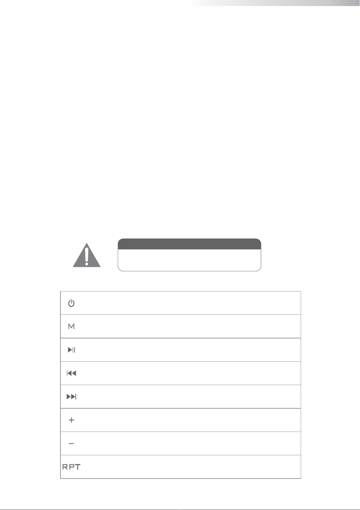
Media Player Button Functions
Power button for media player, press and hold
for on/off function
Mode button press to select player functions
Play and paused control for USB/SD/MMC and Bluetooth mode
Press & Hold: Auto scan function for tuner mode
Previous track when in USB,SD/MMC,Bluetooth Mode
Previous stored FM radio station when in FM tuner Mode
Next track when in USB,SD/MMC,Bluetooth Mode
Next stored FM radio station when in FM tuner Mode
Increase player volume
Reduce player volume
Repeat song, Repeat music folder, Repeat all and Repeat off
DO NOT USE USB PORT TO CHARGE OTHER
DEVICES, THIS WILL DAMAGE THE EQUIPMENT
WARNING
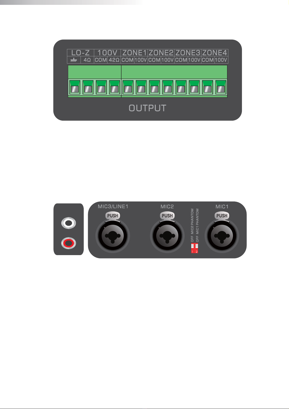
Zone 1-4 on/off button:
The different speaker zone outputs (1-4) can be switched on and off by pressing the
on/off button of the corresponding zone. When the zone (1-4) is enabled the on/off
button will illuminate green to indicate the zone is on. When the ‘All’ button is
pressed all zones will turn on or off.
Zone 1-4 (output) volume control:
The output level of each zone (1-4) can be adjusted separately using the individual
volume knob of each zone.
Power button:
The power button turns the system on or off. The power button will illuminate
green to indicate the power is on and red when the power is off.
Digital Music player:
This is an All-In-One media source has 3 functions including an MP3 player, FM
tuner and Bluetooth. Player supports MP3, WMA, WAV, FLAC, AAC audio
formats.
USB/SD/MMC Connections:
Digital music can be played through these inputs, music will automatically start to
play when the storage medium is connected.

Setting up the system
ATTENTION!
Make sure the power of the device is turned OFF before any wiring connections or
adjustments are made.
1) Connecting the Speakers
The speakers connect to the 2 terminal blocks on the back panel of the device.
This device is compatible with low impedance and constant voltage speakers
depending on the projects requirements.
For operating using the low impedance output, speakers with a minimum
impedance load of 4 ohms or greater can be used.
4Ω
8Ω 8Ω
OR
Example diagram low impedance connections
*Please note the positive amplifier output should be connected to the positive
terminal of the speaker and the ground or negative terminal of the amplifier should
be connected to the negative speaker terminal.
ATTENTION
THE TOTAL IMPEDANCE OF ALL CONNECTED SPEAKERS MUST
BE GREATER THAN THE RATED IMPEDANCE OF THE AMPLIFIER

matching
transformer
matching
transformer
matching
transformer
matching
transformer
matching
transformer
Example diagram constant voltage connections
2) Connecting the audio sources
The next step is adding source input connections. Depending of the type, connect
the output of the audio source to the corresponding input channel.
Before connecting, turn all the channel gain and master volume controls on the
front and rear panel of the amplifier to their minimum setting. Connect all the audio
sources to their corresponding channels. Turn on the power of the amplifier and all
the connected audio sources.
Set the rear panel input gain levels to 50% then slowly raise the master volume
control until the desired sound output level is achieved. Depending of the output
level of the connected sources the input gain may need additional adjustment.
If the signal is too loud or distorted, adjust the input level controls as necessary to
achieve the desired speaker level.

3) Phantom power
MIC input 1 & 2 inputs have phantom power for powering condenser
microphones. Enabling of the phantom power can be done by the switches located
between MIC 1 & 2 connections. Switch 2 will enable phantom power to input 1,
while switch 1 enables phantom power to input 2.
4) Audio Player
Insert a USB storage device or SD/MMC memory card into the front of the device.
The MP3 player is compatible with MP3, WMA, WAV, FLAC, AAC audio
formats. When the media is inserted, the device will automatically start playing.
You can select the playing tracks using the control buttons on front of the device.
For Bluetooth or Tuner audio press the “M” mode button to select.
5) Bluetooth
Adjust the Bluetooth antenna to a vertical position, and then press the M button on
front to switch the operation mode to Bluetooth. Turn on the Bluetooth on your
and search for Bluetooth devices, you’ll find a device named “Bluetooth” in the list,
select and connect to it. Once you connect successfully you can play music from
your device. Use the Back, Forward and Play/Pause buttons to control the music.
6) Radio Tuner
Extent the tuner antenna out and up for best reception. Press and hold the play/
pause button to scan and store available radio stations. After auto scan is complete
use the forward and back buttons to select stations.

Pin connections and connectors
CONNECTION STANDARDS
The input and output connections correspond to international wiring standards
for professional audio equipment.
RCA (Cinch):
For unbalanced line input connections.
Tip:
White:
Signal
Left
Sleeve:
Red:
Ground
Right
XLR:
For balanced signal input connections
Pin 1:
Pin 2:
Pin 3:
Ground
Signal +
Signal
6.3 mm (1/4”) balanced Jack:
For balanced line in & output connections.
Tip:
Ring:
Sleeve:
Signal +
Signal
Ground
6.3 mm (1/4”) unbalanced Jack:
For unbalanced line in & output connections.
Tip:
Sleeve:
Signal
Ground

System
Block
diagram
+35V
+24V
+18V
+12V
+5V
GND
AC 230V-240V/50-60Hz
POWER SUPPLY
DC 24V
EMERGENCY INPUT
24V DC
GAIN
MIC1-MIC2
MIC3/LINE1
LINE2/LINE3
PL
AYER
FM ANT BT ANT
CH
PL
AYER LEVEL
GND
TEL IN
GND
CHIME IN
CH
GND
FIRE IN
FIRE
LINE OUT
TONE CONTROL
70V
70V
50V
35V
25V
COM
INDICATOR
4-8 OHM OUTPUT
70V
DIRECT OUTPUT
70V
ZONE1-4 OUTPUT
ZONE
OUTPUT
SELECTION
ZONE VOLUME
CONTROL
PROTECTOR
POWER
AMPLIFIER
MASTER
100Hz 10kHz
MUTE
MUTEMUTE
NORMAL0
NORMAL1
NORMAL2
NORMAL3
NORMAL3
NORMAL2
NORMAL1
NORMAL0
PRIORITY0
PRIORITY
PRIORITY[0:1]
NORMAL[0:3]
INPUT-LEVEL
GND
PHANTOM
+24V
PRIORITY1
PRIORITY
INPUT-LEVEL
GND
INPUT-LEVEL
PRIORITY0
PRIORITY1
OUTPUT TRANSFORMER
L
R

Technical specifications
RMS Output Power
(1 kHz, THD 1%)
RPA60
RPA120
RPA240
Frequency response
Signal to Noise Ratio THD
+ N
Common Mode Rejection
Crosstalk
Inputs
120 Watt
240 Watt
20Hz - 20kHz
> 90dB
< 0.5%
< 0.5%
> 70dB
2 x Stereo line
Power /Zone/Output
Player
Protect
4Ω
167Ω - RPA60
84Ω - RPA120
42Ω - RPA240
Priority mic inputs
Terminal block ~ 5.08 mm
-30dB
2 x RCA
Balanced mic / line
-50dB
XLR/6.3mm Jack combo
Yes
2 x Balanced mic / line
-50dB
2 x XLR/6.3mm Jack combo
15 V DC
Yes
MIC 1 - 2
LINE 1/MIC 3
LINE 2 - 3
Chime/Fire/TEL
Type
Type
Type
Low Impedance
Constant Voltage Impedance
Connectors
Sensitivity
Connectors
Sensitivity
Connectors
Priority
Type Sensitivity
Connectors
Phantom power
Priority
Outputs
Indicators LED
LCD
Sound
Fan cooled
Class A/B
AC 230V-240V / 50-60Hz
DC 24V
DC - Shor t Circuit
Over Heating Over
Load Limiter
Protection
Cooling system
Amplifier technology
Power supply Master
Standby
OTG 2.0 full-speed controller
USB 2.0 Type-A
USB
Player Type
Connector
Non-self-locking SD card slot
SD/MMC Connector
Bluetooth Bluetooth Ver 2.0 + EDR
10m(without interference)
2402 - 2480 MHz
Version
Maximun range
Trans. Frequencies
MP3/WAV/WMA/FLAC(8/16/24bit)
FAT16 or FAT32
Music formats
File system
87.5 MHZ to 107.9
MHz 75 Ω unbalanced
FM Section Tuning range
Antenna input
60 Watt

5-Year Limited Warranty
Rave Technology products are warranted to be free from defects
in workmanship and materials for a period of Five (5) years
from the date of purchase without charge for parts or labor. This
warranty does not apply to units that have been subject to
misuse, abuse, neglect or improper installation, and does not
apply to repairs or alterations made by unauthorized
professional. This warranty specifically excludes responsibility
for consequential damage. Retention of your original bill of sale
is required to obtain service under the terms of this warranty.
© 2020 Rave Technology. All rights reserved.
All trademarks are the property of their respective owners.
Specifications are subject to change without notice.
Rave Technology
4100 East Baldwin Road Holly,
Michigan, 48442 USA
Tel: 866-303-2629
Email: [email protected]
WWW.RAVETECHNOLOGY.COM
This manual suits for next models
2
Table of contents
Other Rave Amplifier manuals