Raycap ProSMS 8 User manual

Installation Manual:
ProSMS 8
Protection and Monitoring Solution
for PV Systems
www.raycap.com
INSTALLATION MANUAL ProSMS 8


2017 ©Raycap • All rights reserved
130 620 300 Rev.C 171116
Page 3 of 24
www.raycap.com
INSTALLATION MANUAL ProSMS 8
Contents
1.1 Copyright ............................................................................................................. 4
1.2 Introduction ......................................................................................................... 4
2.1 Disclaimer ............................................................................................................ 4
2.2 Warnings .............................................................................................................. 4
2.3 Symbols ............................................................................................................... 5
3.1 Package contents................................................................................................ 5
3.2 Prerequisites........................................................................................................ 5
3.3 Installation tools.................................................................................................. 5
4.1 Device overview................................................................................................... 6
5.1 Installation ........................................................................................................... 7
5.2 Device setting ...................................................................................................... 7
5.3 Cabling recommendations ................................................................................. 8
5.4 Digital Input/Output............................................................................................. 9
6.1 MODBUS interface ............................................................................................ 10
6.2 MODBUS typical communication connections .............................................. 11
6.3 ProSMS settings................................................................................................ 13
6.4 MODBUS registers ............................................................................................ 15
7.1 Device operation ............................................................................................... 20
7.2 Energy measurement per string ...................................................................... 20
7.3 Operation principles ......................................................................................... 21
7.4 Min/Max measurement...................................................................................... 22
7.5 Surge counter .................................................................................................... 22
8.1 Technical data.................................................................................................... 23

2017 ©Raycap • All rights reserved
130 620 300 Rev.C 171116
Page 4 of 24
ProSMS 8 INSTALLATION MANUAL
www.raycap.com
1.1 Copyright
©Raycap, Inc. 2017 - All Rights Reserved
1.2 Introduction
String monitoring enables early detection of site failures such as the loss of output or the failure of a
particular Photovoltaic (PV) panel, and can minimize energy losses and expand the lifetime of a PV
system.
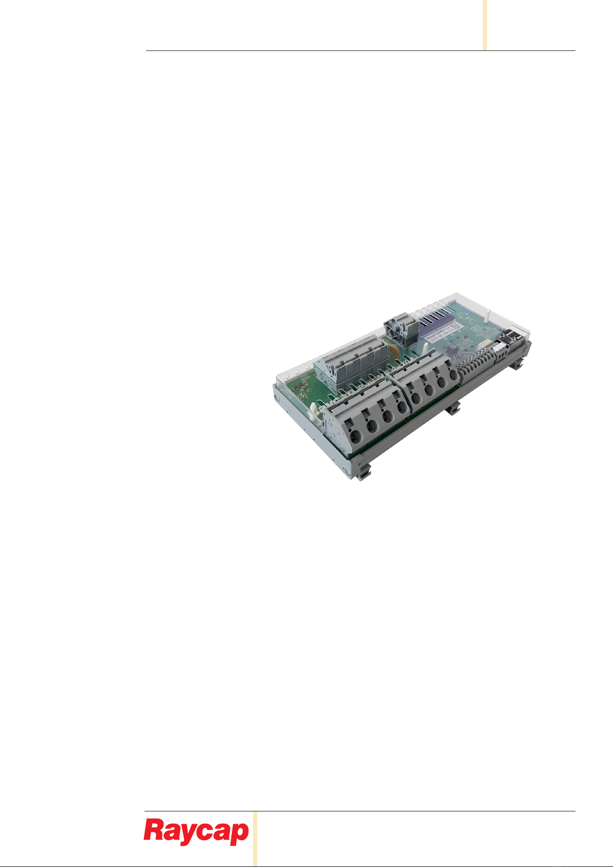
The Raycap ProSMS 8 string monitoring solution has innovative features including surge protected
inputs, the ability to remotely detect bad contacts, and a range of communication
options that enable PV park operators to immediately understand and respond to eld maintenance
needs, resulting in reduced operating expenses.
For conditions other than those described above, please contact a Raycap Account Representative at
sales@raycap.com
Thank you for choosing quality products from Raycap.
2.1 Disclaimer
The information in this document is subject to change without notice and describes only the product
dened in the introduction of this documentation. This documentation is intended for the use of Raycap
customers only for the purposes of the agreement under which the document is submitted, and no
part may be used, reproduced, modied or transmitted in any form or means without the prior written
permission of Raycap. The documentation has been prepared to be used by professional and properly
trained personnel, and the customer assumes full responsibility when using it. Raycap welcomes
customer comments as part of the process of continuous development and improvement of the
documentation.
Raycap has made all reasonable efforts to ensure that the instructions contained in this document are
adequate and free of material errors and omissions. Raycap will, if deemed necessary, explain issues
which may not be covered by this document.
The contents of this document are subject to revision without notice due to continued progress in
methodology, design and manufacturing. Raycap shall have no liability for any error damage of any kind
resulting from the use of this document.
2.2 Warnings
Please read this manual before using ProSMS 8. It is important to become familiar with the product’s
numerous features and operating procedures. To maintain the maximum degree of safety, follow the
sequences as outlined.
Before using the product, read all instructions and cautionary markings on the product and on any
equipment connected to the product.
Unless otherwise noted, product usage that is not recommended or sold by the product
manufacturer can result in risk of re, electric shock, or injury to persons.
Do not operate the product if it has been damaged in any way. Return damaged products to
their manufacturer for repair or replacement.
Do not disassemble the product as incorrect reassembling can risk electrical shock or re.
Disconnect or disable the DC power source to the product prior to beginning its installation.
Ensure that the DC power source to the product remains de-energized until the completion of
the installation and after all connections have been veried to be correctly congured.
If the equipment is used in a manner not specied by the manufacturer, the protection
provided by the device may be impaired.
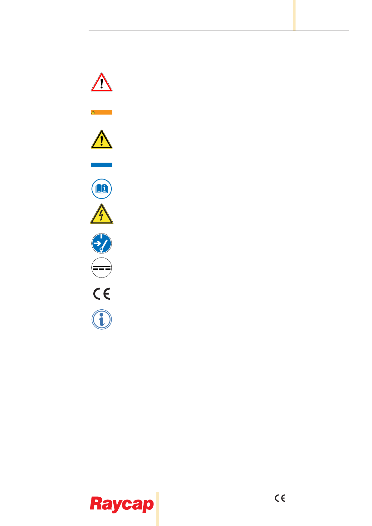
CAUTION
VOLTAGE
DANGER
WARNING
NOTICE
CAUTION
VOLTAGE
DANGER
WARNING
NOTICE

2017 ©Raycap • All rights reserved
130 620 300 Rev.C 171116
Page 5 of 24
www.raycap.com
INSTALLATION MANUAL ProSMS 8
2.3 Symbols
The DANGER sign denotes a hazard. It calls attention to a procedure, practice, or the like,
which, if not correctly performed or adhered to, could result in personal injury or death. Do not
proceed beyond a DANGER sign until the indicated conditions are fully understood and met.
The WARNING sign denotes a hazard. It calls attention to a procedure, practice, or the like,
which, if not correctly performed or adhered to, could result in personal injury or death. Do not
proceed beyond a WARNING sign until the indicated conditions are fully understood and met.
The Caution sign indicates a hazardous situation which, if not avoided, could result in minor
or moderate injury.
The Indication sign Indicates a situation that can result in property or device damage if not
avoided.
Refer to all the documentation supplied with the ProSMS String Monitor Solution.
Warning of dangerous electrical voltage. The ProSMS String Monitor solution is connected to
high voltages. All work on the device must only be carried out by electrically skilled persons.
Disconnect before installing, removing, carrying out maintenance or repair.
Direct current marking (DC)
The CE marking is the legal required labeling for several EU Directives of the European
Union. This CE marking shows that the product complies with all the relevant European
Legal Directives.
Indicates important information.
3.1 Package contents
1 ProSMS 8 unit
3.2 Prerequisites
This document describes how to install the ProSMS 8. It covers how to mount the units as well as
connections to its interfaces.
Installers of Raycap’s ProSMS 8 should read this installation guide thoroughly prior to installation of the
unit.
3.3 Installation tools
WAGO 210-721 Type 3 partially insulated Operating Tool (5.5 mm Blade, 0.8 mm Tip) or similar
(Common negative output, String inputs and Voltage input terminals)
WAGO 210-619 Type 1 partially insulated Operating Tool (2.5 mm Blade, 0.4 mm Tip) or similar
(MODBUS, digital inputs, digital outputs terminals and DIP switch settings)
CAUTION
VOLTAGE
DANGER
WARNING
NOTICE
CAUTION
VOLTAGE
DANGER
WARNING
NOTICE
CAUTION
VOLTAGE
DANGER
WARNING
NOTICE
CAUTION
VOLTAGE
DANGER
WARNING
NOTICE
CAUTION
VOLTAGE
DANGER
WARNING
NOTICE
CAUTION
VOLTAGE
DANGER
WARNING
NOTICE
CAUTION
VOLTAGE
DANGER
WARNING
NOTICE
CAUTION
VOLTAGE
DANGER
WARNING
NOTICE
CAUTION
VOLTAGE
DANGER
WARNING
NOTICE
CAUTION
VOLTAGE
DANGER
WARNING
NOTICE

2017 ©Raycap • All rights reserved
130 620 300 Rev.C 171116
Page 6 of 24
ProSMS 8 INSTALLATION MANUAL
www.raycap.com
4.1 Device overview
String monitoring enables the early detection of site failures such as the loss of output or the failure of a
particular Photovoltaic (PV) panel, and can minimize energy losses and extend the operating lifetime of
a PV system.
The Raycap ProSMS 8 string monitoring solution has some unique and innovative features in
comparison to basic string monitoring solutions. These include:
• Build-in power supply. ProSMS is self-powered from the strings being monitored
• Built-in surge protection on all inputs
• Internal energy measurement of each connected string and total power measurement.
• Dynamic averaging value registers. Reports precise voltage mean value and current between
two reads from MODBUS master
• Minimum and Maximum current values
• Positive or Negative current ow indication
• Integrated surge event counter
• User-congurable relay output for general remote control of auxiliary equipment
• Built-in communication diagnostic registers per MODBUS standard
These features assist PV system operators to better understand and respond to eld maintenance
needs, thereby resulting in reduced operating expense and potential downtime.
Fig. 4-1: Device overview – front side of ProSMS 8
Position Description
A Input negative terminal from string 1 through 4 (max 30A per string)
B Input negative terminal from string 5 through 8 (max 30A per string)
C Output common terminal from string 1 through 8
D Voltage sense terminal (ProSMS powers itself from this terminal)
E Modbus interface terminals. Two parallel GND, A, B terminals each
F Digital input terminals. Use potential free contact closure of DIN1 & DIN2 to DCOM
G Signal relay output with change-over contacts
HDIP switches used for settings system conguration and modubus address
I Status LEDs. green for power, yellow communication, red for error
J Power supply heatsink. Do not cover!

2017 ©Raycap • All rights reserved
130 620 300 Rev.C 171116
Page 7 of 24
www.raycap.com
INSTALLATION MANUAL ProSMS 8
5.1 Installation
Very high voltages are present on this ProSMS device.
Disconnect the PV Array and make sure all sources of power are locked out
before performing any work, removing or mounting the device.
For proper operation, external surge protection in combination with correct overcurrent fusing
must be provided in the combiner box where the device is installed, otherwise the ProSMS
device may be damaged. Overcurrent fusing should be installed on all string channels,
preferable on the negative side (ref. picture below).
The unit should be installed in an enclosure with at least IP5x (dust test) environmental rating
per IEC60529.
5.2 Device setting
Before powering device for the rst time set device address and communication options as per the
ProSMS settings tables on page 13.
No reboot or removing/applying power is necessary for changes in settings or address to take
effect. ProSMS has an advanced built in mechanism that recognizes settings change and
sets internal parameters to match the settings immediately when settings are changed. This
also applies to baud rate and parity change.
CAUTION
VOLTAGE
DANGER
WARNING
NOTICE
CAUTION
VOLTAGE
DANGER
WARNING
NOTICE
CAUTION
VOLTAGE
DANGER
WARNING
NOTICE
CAUTION
VOLTAGE
DANGER
WARNING
NOTICE
CAUTION
VOLTAGE
DANGER
WARNING
NOTICE
(Insert #1)
Note: Only colors of the Central inverter can be changed if necessary. Please don’t change the
connection Lines colors anymore!!! It is important that Common + is Red and Common - is Blue!
These two colors are common representation for positive and negative potential of a DC system!

2017 ©Raycap • All rights reserved
130 620 300 Rev.C 171116
Page 8 of 24
ProSMS 8 INSTALLATION MANUAL
www.raycap.com
5.3 Cabling recommendations
String input connections (S1IN .. S8IN)
• For 30A per string installations, 6mm² tinned double insulated ne stranded cable (tted with
ferrules) is required.
•Cables with lower cross-sectional area may be used for installations where less than 20A per
string can be expected.
String output connections (COMMON)
•When ProSMS 8 is operating at full capacity (30A per string, 240A total), four 16mm2tinned
double insulated ne stranded cable (without ferrules) is required
•Cables with lower cross-sectional area may be used for installations where less than 20A per
string can be expected.
String voltage measurement connections (+1000VDC)
• At least 1mm² tinned, double insulated, ne stranded, cable with ferrules, is required.
MODBUS (GND,A,B)
•Shielded twisted–pair cable, designed for RS485 interfacing is required. Cable should have at
least two twisted pairs with cross–section area of 0.2mm2(24AWG) up to 0.5mm2(20AVG).
•Cable should have a characteristic impedance of 100–120 ohm for optimal performance.
Digital inputs (DIN1,DIN2)
•Any appropriate cable up to 1mm² with ferrules, or 1.5mm² without ferrules may be used.
Digital outputs (NO,C,NC)
• Any appropriate cable up to 1.5mm² with ferrules, or 2.5mm² without ferrules, may be used.

2017 ©Raycap • All rights reserved
130 620 300 Rev.C 171116
Page 9 of 24
www.raycap.com
INSTALLATION MANUAL ProSMS 8
5.4 Digital Input/Output
Two potential-free digital inputs are provided on the ProSMS to facilitate the monitoring of external
ancillary equipment. Examples may include: monitoring of installed SPD, cabinet door, interlock
switches, alarm functions etc. These inputs are by default internally pulled to 5V. In order to activate the
digital inputs they must be connected to the DCOM terminal via potential-free contact closures. Contact
closure is read as value 1 (Contact ON). The status of these two auxiliary inputs are read from the
Modbus input register 00052 (see page 15).
The ProSMS also provides an optional output control via the SPDT relay contacts. These contacts can
be used for a variety of purposes, such as the control of a safety disconnect switch, or the signal to a
PLC or other relay/contactor. The output is controlled by writing to the Modbus holding register 00000
(see page 16).
Relay output terminals and connecting wiring should not be accessible to the user when
the device is powered. The relay provides only functional insulation to PV potential
(2000Vrms@1min). Connections and wiring should not extend outside the combiner box
enclosure.
CAUTION
VOLTAGE
DANGER
WARNING
NOTICE
Fig. 5-4: Typical wiring of poten�al free inputs and relay output
Fig. 5-4: Typical wiring of potential free inputs and relay output

2017 ©Raycap • All rights reserved
130 620 300 Rev.C 171116
Page 10 of 24
ProSMS 8 INSTALLATION MANUAL
www.raycap.com
6.1 MODBUS interface
The MODBUS interface is not intended to be accessible to the user during operation.
The MODBUS interface is protected by a three-stage built-in circuit which meets IEC 61643-
21 class D1/C1/C2/C3. There is no need to install additional external DATA protection devices.
Fig. 6-1: Example of master at beginning of bus
Fig. 6-2: Example of master in the middle of bus
• Use one twisted pair for A and B signals
•Connect both wires of the remaining twisted pair to GND MODBUS Terminal
•If a cable has more than two twisted pairs, connect all unused pairs to GND MODBUS
terminals at each ProSMS unit. For optimal data communication, do not leave these oating
•The last unit in the chain must be terminated with a 120 ohm resistor
•GND Modbus wires (Data signal common potential) should be grounded once at the master
unit
•Cable shield should be grounded at each combiner box or at least at the Master unit with all
shields in all combiner boxes connected together
•The Master unit must be terminated with a 120 ohm resistor if it is at the beginning of the bus
CAUTION
VOLTAGE
DANGER
WARNING
NOTICE
CAUTION
VOLTAGE
DANGER
WARNING
NOTICE
(Insert #2)
(Insert #3)
(Insert #2)
(Insert #3)

2017 ©Raycap • All rights reserved
130 620 300 Rev.C 171116
Page 11 of 24
www.raycap.com
INSTALLATION MANUAL ProSMS 8
6.2 MODBUS typical communication connections
The ProSMS provides duplicate MODBUS interface terminals (GND, A, B). Communication cabling from
the previous device, and cabling to the next device, can be directly connected to these terminals to save
cost (Fig. 6-3).
For more convenient eld installation a larger intermediate external communication terminal can be
added in the cabinet (Fig. 6-4). When using an external terminal, cable lengths of less than 1m are
recommended. The cable from the intermediate terminal to the ProSMS does not have to be the same
as the main communication cable and can be of a smaller cross-section, for example: 0.2mm2but still
needs to be RS485 certied twisted pair shielded cable.
The third solution with external terminals is to wire both RS485 connections from ProSMS to the
external terminal (Fig. 6-5) so no Stub forms in the communication bus but care has to be taken to use
the same cross-section and electrical properties cable as it’s used for the main lines between combiner
boxes.
The second solution (Fig. 6-4) is recommended since it provides a good compromise between
connection convenience and reliability.
Fig. 6-3: Direct MODBUS cabling connec�on to ProSMS in combiner box enclosure
CAUTION
VOLTAGE
DANGER
WARNING
NOTICE
Fig. 6-3: Direct MODBUS cabling connection to ProSMS in combiner box enclosure

2017 ©Raycap • All rights reserved
130 620 300 Rev.C 171116
Page 12 of 24
ProSMS 8 INSTALLATION MANUAL
www.raycap.com
6.2 MODBUS typical communication connections (continued)
Fig. 6-4: MODBUS cabling connection to ProSMS via intermediate connection terminal in combiner box
enclosure
Fig. 6-5: MODBUS cabling connection to ProSMS via intermediate connection terminal in combiner box
enclosure (No Stub variant)

2017 ©Raycap • All rights reserved
130 620 300 Rev.C 171116
Page 13 of 24
www.raycap.com
INSTALLATION MANUAL ProSMS 8
6.3 ProSMS settings
MODBUS address (Address DIP Switch 1..7)
• Any valid MODBUS address between 1 and 247 can be selected using the on-board DIP
switches. The switches are 2nbinary coded. Address on each ProSMS 8 is factory preset to Nr. 5.
•Address can be changed during operation, no restart or power cycle is required.
Communication settings (DIP switch 1..6)
1 2 3 4 5 6 7 8 DIP Switch Position
1 0 0 0 0 0 0 0 Slave address #1
0 1 0 0 0 0 0 0 Slave address #2
1 1 0 0 0 0 0 0 Slave address #3
0 0 1 0 0 0 0 0 Slave address #4
1 0 1 0 0 0 0 0 Slave address #5
• • • • • • • • •
• • • • • • • • •
1 1 0 0 1 1 1 1 Slave address #243
0 0 1 0 1 1 1 1 Slave address #244
1 0 1 0 1 1 1 1 Slave address #245
0 1 1 0 1 1 1 1 Slave address #246
1 1 1 0 1 1 1 1 Slave address #247
DIP Switch Position 1 2 3 Meaning (Baud Rate)
0 0 0 2400 bps
1 0 0 4800 bps
0 1 0 9600 bps
1 1 0 19200 bps
0 0 1 38400 bps - factory preset
DIP Switch Position 4 5 Meaning (Parity)
0 0 None (2 stop bits)
1 0 Odd (1 stop bit)
0 1 Even (1 stop bit) - factory preset
DIP Switch Position 6 Meaning
0 Normal timing requirements for master - factory preset
1 Relaxed timing requirements for master
• For harsh environments or areas with high EM disturbances. It might be needed to set baud
rate to a lower speed.

2017 ©Raycap • All rights reserved
130 620 300 Rev.C 171116
Page 14 of 24
ProSMS 8 INSTALLATION MANUAL
www.raycap.com
• All settings can be changed during operation, no restart or power cycle is needed
•Relaxed timing feature increases the MODBUS standard timing by a set factor.
This can be helpful for problematic master units. MODBUS protocol uses two time
restrictions per standard:
- t1.5 is 1.5x the character time at given baud rate and is the maximum time allowed
between two received character bytes before the whole received packed is out of
specication and considered bad.
- t3.5 is 3.5x the character time at given baud rate and is used for end of message
detection.
When relaxed timing is enabled by DIP switch, ProSMS uses this additional timing factor
located in RELAXED_TIMING register to extend t1.5 and t3.5 timing limits.
Settings lock (DIP Switch 7)
• Settings can be additionally locked. When locked an accidental change of switches has no
inuence on the conguration.
System reset (DIP Switch 8)
• Hardware reset of ProSMS device (does not effect any settings or saved values).

2017 ©Raycap • All rights reserved
130 620 300 Rev.C 171116
Page 15 of 24
www.raycap.com
INSTALLATION MANUAL ProSMS 8
6.4 MODBUS registers
Input registers, MODBUS function 4
Register ID Address Data Type Possible Values Unit Description R/W
ENERGY_STR01 0000,0001 INT32 ±2147483647 kWh*100 Accumulated energy string 1 [LSW is 0000, MSW is 0001] R
ENERGY_STR02 0002,0003 INT32 ±2147483647 kWh*100 Accumulated energy string 2 [LSW is 0002, MSW is 0003] R
ENERGY_STR03 0004,0005 INT32 ±2147483648 kWh*100 Accumulated energy string 3 [LSW is 0004, MSW is 0005] R
ENERGY_STR04 0006,0007 INT32 ±2147483649 kWh*100 Accumulated energy string 4 [LSW is 0006, MSW is 0007] R
ENERGY_STR05 0008,0009 INT32 ±2147483650 kWh*100 Accumulated energy string 5 [LSW is 0008, MSW is 0009] R
ENERGY_STR06 0010,0011 INT32 ±2147483651 kWh*100 Accumulated energy string 6 [LSW is 0010, MSW is 0011] R
ENERGY_STR07 0012,0013 INT32 ±2147483652 kWh*100 Accumulated energy string 7 [LSW is 0012, MSW is 0013] R
ENERGY_STR08 0014,0015 INT32 ±2147483653 kWh*100 Accumulated energy string 8 [LSW is 0014, MSW is 0015] R
ENERGY_STR09 0016,0017 INT32 ±2147483654 kWh*100 Accumulated energy string 9 [LSW is 0016, MSW is 0017] R
ENERGY_STR10 0018,0019 INT32 ±2147483655 kWh*100 Accumulated energy string 10 [LSW is 0018, MSW is 0019] R
ENERGY_STR11 0020,0021 INT32 ±2147483656 kWh*100 Accumulated energy string 11 [LSW is 0020, MSW is 0021] R
ENERGY_STR12 0022,0023 INT32 ±2147483657 kWh*100 Accumulated energy string 12 [LSW is 0022, MSW is 0023] R
ENERGY_STR13 0024,0025 INT32 ±2147483658 kWh*100 Accumulated energy string 13 [LSW is 0024, MSW is 0025] R
ENERGY_STR14 0026,0027 INT32 ±2147483659 kWh*100 Accumulated energy string 14 [LSW is 0026, MSW is 0027] R
ENERGY_STR15 0028,0029 INT32 ±2147483660 kWh*100 Accumulated energy string 15 [LSW is 0028, MSW is 0029] R
ENERGY_STR16 0030,0031 INT32 ±2147483660 kWh*100 Accumulated energy string 16 [LSW is 0030, MSW is 0031] R
CURRENT_STR01 0032 INT16 -32000..+32000 mA Current string 1 R
CURRENT_STR02 0033 INT16 -32000..+32000 mA Current string 2 R
CURRENT_STR03 0034 INT16 -32000..+32000 mA Current string 3 R
CURRENT_STR04 0035 INT16 -32000..+32000 mA Current string 4 R
CURRENT_STR05 0036 INT16 -32000..+32000 mA Current string 5 R
CURRENT_STR06 0037 INT16 -32000..+32000 mA Current string 6 R
CURRENT_STR07 0038 INT16 -32000..+32000 mA Current string 7 R
CURRENT_STR08 0039 INT16 -32000..+32000 mA Current string 8 R
CURRENT_STR09 0040 INT16 -32000..+32000 mA Current string 9 R
CURRENT_STR10 0041 INT16 -32000..+32000 mA Current string 10 R
CURRENT_STR11 0042 INT16 -32000..+32000 mA Current string 11 R
CURRENT_STR12 0043 INT16 -32000..+32000 mA Current string 12 R
CURRENT_STR13 0044 INT16 -32000..+32000 mA Current string 13 R
CURRENT_STR14 0045 INT16 -32000..+32000 mA Current string 14 R
CURRENT_STR15 0046 INT16 -32000..+32000 mA Current string 15 R
CURRENT_STR16 0047 INT16 -32000..+32000 mA Current string 16 R
VOLTAGE 0048 UINT16 00..16000 V* 10 System voltage R
VOLTAGE_ANALOG1 0049 INT16 -1000..+1000 V* 100 Analog input voltage 1 R
VOLTAGE_ANALOG2 0050 INT16 -1000..+1000 V* 100 Analog input voltage 2 R
TEMP_ENCLOSURE 0051 INT16 -400..+1600 ºC* 10 Temperature of string monitor enclosure R
DIGITAL_INPUTS 0052 UINT16 0x0000..0x0003 Bits Digital inputs [LSB inputs, MSB alarms] R
CURRENT_AVE_STR01 0053 INT16 -32000..+32000 mA Average current string 1 R
CURRENT_AVE_STR02 0054 INT16 -32000..+32000 mA Average current string 2 R
CURRENT_AVE_STR03 0055 INT16 -32000..+32000 mA Average current string 3 R
CURRENT_AVE_STR04 0056 INT16 -32000..+32000 mA Average current string 4 R
CURRENT_AVE_STR05 0057 INT16 -32000..+32000 mA Average current string 5 R
CURRENT_AVE_STR06 0058 INT16 -32000..+32000 mA Average current string 6 R
CURRENT_AVE_STR07 0059 INT16 -32000..+32000 mA Average current string 7 R
CURRENT_AVE_STR08 0060 INT16 -32000..+32000 mA Average current string 8 R
CURRENT_AVE_STR09 0061 INT16 -32000..+32000 mA Average current string 9 R
CURRENT_AVE_STR10 0062 INT16 -32000..+32000 mA Average current string 10 R
CURRENT_AVE_STR11 0063 INT16 -32000..+32000 mA Average current string 11 R
CURRENT_AVE_STR12 0064 INT16 -32000..+32000 mA Average current string 12 R
CURRENT_AVE_STR13 0065 INT16 -32000..+32000 mA Average current string 13 R
CURRENT_AVE_STR14 0066 INT16 -32000..+32000 mA Average current string 14 R
CURRENT_AVE_STR15 0067 INT16 -32000..+32000 mA Average current string 15 R
CURRENT_AVE_STR16 0068 INT16 -32000..+32000 mA Average current string 16 R
VOLTAGE_AVE 0069 UINT16 0..16000 V* 10 Average system voltage R
TEMP_ENCLOSURE_AVE 0070 INT16 -400..+1600 ºC* 10 Average temp of string monitor enclosure R
SURGE COUNTER 0071 INT16 0..65536 Counts Detected lightning surges R
FREE_0 0072 INT16 R
FREE_1 0073 INT16 R
Accumulated ValuesInstantaneous Values (Last 4s)Surge Integrated Values from last reading to present
(Maximum Integration Time 24h)

2017 ©Raycap • All rights reserved
130 620 300 Rev.C 171116
Page 16 of 24
ProSMS 8 INSTALLATION MANUAL
www.raycap.com
Input registers, MODBUS function 4 (continued)
• Averaging registers are reset on each read, so the correct average between two master reads
is always reported correctly. The time between consecutive readings on each new reading does
not need to be constant, but there is a maximum integration time of 24 hours.
•Min/Max current registers are automatically updated. It is not necessary to reset them manually.
•Energy holding registers are accumulating registers that are saved during device power down.
They can be cleared to 0 with the "Reset Accumulated Energy KWh Counters" command
if needed (See Command's section on page 17).
Bit locations of DIGITAL_INPUTS register
Register ID Address Data Type Possible Values Unit Description R/W
CURRENT_MIN_STR01 0074 INT16 -32000..+32000 mA Minimum current string 1 R
CURRENT_MIN_STR02 0075 INT16 -32000..+32000 mA Minimum current string 2 R
CURRENT_MIN_STR03 0076 INT16 -32000..+32000 mA Minimum current string 3 R
CURRENT_MIN_STR04 0077 INT16 -32000..+32000 mA Minimum current string 4 R
CURRENT_MIN_STR05 0078 INT16 -32000..+32000 mA Minimum current string 5 R
CURRENT_MIN_STR06 0079 INT16 -32000..+32000 mA Minimum current string 6 R
CURRENT_MIN_STR07 0080 INT16 -32000..+32000 mA Minimum current string 7 R
CURRENT_MIN_STR08 0081 INT16 -32000..+32000 mA Minimum current string 8 R
CURRENT_MIN_STR09 0082 INT16 -32000..+32000 mA Minimum current string 9 R
CURRENT_MIN_STR10 0083 INT16 -32000..+32000 mA Minimum current string 10 R
CURRENT_MIN_STR11 0084 INT16 -32000..+32000 mA Minimum current string 11 R
CURRENT_MIN_STR12 0085 INT16 -32000..+32000 mA Minimum current string 12 R
CURRENT_MIN_STR13 0086 INT16 -32000..+32000 mA Minimum current string 13 R
CURRENT_MIN_STR14 0087 INT16 -32000..+32000 mA Minimum current string 14 R
CURRENT_MIN_STR15 0088 INT16 -32000..+32000 mA Minimum current string 15 R
CURRENT_MIN_STR16 0089 INT16 -32000..+32000 mA Minimum current string 16 R
CURRENT_MAX_STR01 0090 INT16 -32000..+32000 mA Maxmimum current string 1 R
CURRENT_MAX_STR02 0091 INT16 -32000..+32000 mA Maxmimum current string 2 R
CURRENT_MAX_STR03 0092 INT16 -32000..+32000 mA Maxmimum current string 3 R
CURRENT_MAX_STR04 0093 INT16 -32000..+32000 mA Maxmimum current string 4 R
CURRENT_MAX_STR05 0094 INT16 -32000..+32000 mA Maxmimum current string 5 R
CURRENT_MAX_STR06 0095 INT16 -32000..+32000 mA Maxmimum current string 6 R
CURRENT_MAX_STR07 0096 INT16 -32000..+32000 mA Maxmimum current string 7 R
CURRENT_MAX_STR08 0097 INT16 -32000..+32000 mA Maxmimum current string 8 R
CURRENT_MAX_STR09 0098 INT16 -32000..+32000 mA Maxmimum current string 9 R
CURRENT_MAX_STR10 0099 INT16 -32000..+32000 mA Maxmimum current string 10 R
CURRENT_MAX_STR11 0100 INT16 -32000..+32000 mA Maxmimum current string 11 R
CURRENT_MAX_STR12 0101 INT16 -32000..+32000 mA Maxmimum current string 12 R
CURRENT_MAX_STR13 0102 INT16 -32000..+32000 mA Maxmimum Current String 13 R
CURRENT_MAX_STR14 0103 INT16 -32000..+32000 mA Maxmimum current string 14 R
CURRENT_MAX_STR15 0104 INT16 -32000..+32000 mA Maxmimum current string 15 R
CURRENT_MAX_STR16 0105 INT16 -32000..+32000 mA Maxmimum current string 16 R
POWER 0106,0107 INT32 -50000000..+50000000 kW*100 Summed power of all strings [LSW is 0106, MSW is 0107] R
DEVICE_STATUS 0500 UINT16 Bits Status bits R
DEVICE_ID 0501, 0502 UINT32 2x Word Device identication number (130-620) R
SERIAL_NUMBER 0503, 0504 UINT32 2x Word Device serial number (1234-4567) R
SM_CONFIG 00505 UINT16 0x0000..0xFFFF Bits Options present (Bat charging, analog inputs,dig output...) R
VERSION_SOFT 0506 UINT16 2xByte Software version [LSB main, MSB current] R
VERSION_HW 0507 UINT16 2xByte PCB version [LSB Mod#, MSB Letter, A,B,C...] R
PRODUCTION_DATE 0508 UINT16 2xByte Date of production [LSB week, MSB year] R
CALIBRATION_DATE 0509 UINT16 2xByte Date of production [LSB week, MSB year] R
Min/Max Values from last reading to presentHardware Info.
Digital Inputs (0052) Bit Location
Digital Input 1 0
Digital Input 2 1
2
3
4
5
6
7
LSB Digital Inputs

2017 ©Raycap • All rights reserved
130 620 300 Rev.C 171116
Page 17 of 24
www.raycap.com
INSTALLATION MANUAL ProSMS 8
Holding registers, MODBUS function read 3, rite function 6 or 16
Bit location of DIGITAL_OUTPUTS register
• When the DIGITAL_OUTPUTS register is written it is automatically saved to internal EEPROM.
Last register value is always loaded from EEPROM in the case of a power cycle (Night time).
DIGITAL_OUTPUTS (0000) Bit Location
Digital Output #1Relay 0
1
2
3
4
5
6
7
8
9
10
11
12
13
14
15
Digital Outputs
• The response delay (after the Master queries ProSMS and then releases the bus) is typically
3.5 times the baud rate character time, per MODBUS guidelines. If an older Master is
used, then the response from ProSMS may be too fast and data may be corrupted. In such
circumstances, an additional delay of a few milliseconds can be set in the RESPONSE_DELAY
register to aid data integrity.
• ProSMS follows the MODBUS timing guidelines for communication frame Start, Stop and
character-to-character delay. With older Master units, (especially non real-time PC/Linux
based Master units that do not meet required timing), the Relaxed Timing Mode can be used.
In this way ProSMS will allow the Master unit a greater byte-to-byte transmit delay and time
to transmit complete data before agging it as bad. The Relaxed Timing mode is enabled by
setting DIP switch position 6 to ON. When this switch is in the OFF position, timing factor 1 is
used, independent of what factor is set in the RELAXED_TIMING register.
• Example for baud rate set to 19200bps: Character time for this baud rate would be 0.52ms.
Standard permitted maximum character to character delay t1.5 is 0.78ms and end of message
time t3.5 is 1.82ms. With relaxed timing set to 4 (Factor=2) this changes the delay time of t1.5
to 1.56ms and t3.5 to 3.64ms, giving the master twice as much time for a message to be still
accepted by ProSMS as good.
Register ID Address Data Type Possible Values Unit Description R/W
DIGITAL_OUTPUTS 0000 UIN16 0x0000..0xFFFF Bits Digital outputs register R/W
SM_COMMAND 0001 UIN16 0..100 Various commands (KWh reset...) R/W
RESPONSE_DELAY 0005 UIN16 0..100 (coerced) ms To delay responses for master queries R/W
RELAXED_TIMING 0006 UIN16 3..6 (coerced) Factor/2 Relaxed MODBUS t1,5 and t3,5
timing factor (DIPSW enabled) R/W
Output
Settings

2017 ©Raycap • All rights reserved
130 620 300 Rev.C 171116
Page 18 of 24
ProSMS 8 INSTALLATION MANUAL
www.raycap.com
Commands (Write to SM_COMMAND register)
Detailed command description:
1 (0x01) Saves All Changed Holding registers to EEPROM for permanent storage.
To store RESPONSE_DELAY and RELAXED_TIMING registers permanently execute
this command after writing to the Holding registers. DIGITAL_OUTPUTS register is
saved automatically on every write, it is not necessary to execute command 1.
10 (0x0A) Cumulative Energy registers in the device can be cleared to zero if desired.
11 (0x0B) This command clears all the averaging registers. After execution ProSMS starts
creating new averages. It is not necessary to clear the registers during normal
operation as new averages are formed automatically after a read by the Master of at
least one of the averaging registers. This command is intended to allow precise
comparison of the measured average values between multiple ProSMS units following
a multicast write of this command to all units on the bus.
12 (0x0C) This command clears the Min-Max registers. After execution ProSMS starts creating
new minimum and maximum values. It is not necessary to clear the registers during
normal operation as minimum and maximum are formed automatically after a read
by the Master of at least one of the Min-Max registers. This command is intended to
allow a precise comparison of the Min-Max values between multiple ProSMS units
following a multicast write of this command to all units on the bus.
Command Description Note
0 Do nothing
1 Save all changed holding registers to EEPROM Wait 2 seconds after command, exception #6
2
3
4
5
6
7
8
9
10 Reset accumulated energy KWh counters
11 Clear current, voltage, temperature average registers
12 Clear min, max registers
Command #
(Holding register 0001)

2017 ©Raycap • All rights reserved
130 620 300 Rev.C 171116
Page 19 of 24
www.raycap.com
INSTALLATION MANUAL ProSMS 8
Diagnostic registers, MODBUS function Read 8
MODBUS function code 08 provides a series of tests to check communication between the client
(Master) and the Slave (ProSMS), or to check various internal error conditions within the ProSMS. This
functionality is most useful during installation to check that there are no communication problems across
the network before commissioning. It is recommended to read diagnostics registers once per month to
conrm that the network is still performing optimally.
The function uses a two–byte sub-function code eld in the query to dene the type of test to be
performed. ProSMS echoes both the function code and sub-function code in a normal response.
The following diagnostic functions are supported by ProSMS:
Subfunctiondiagnosticreturncodesresponsedataled. Detailed description:
10 (0x0A) Clears all MODBUS diagnostic counters and registers. After the command is issued
all counters start to count from zero.
11 (0x0B) Quantity of messages that the ProSMS has detected on the communications system
since: last power–up (every morning), last clearing of this counters or after a remote
ProSMS restart.
12 (0x0C) Quantity of CRC errors encountered by the ProSMS since: last power–up (every
morning), last clearing of this counters or after a remote ProSMS restart.
13 (0x0D) Quantity of MODBUS exception responses returned by the ProSMS since: last
power–up (every morning), last clearing of this counters or after a remote ProSMS
restart.
14 (0x0E) Quantity of messages addressed to the ProSMS (including broadcast messages)
that the remote device has processed since: last power–up (every morning), last
clearing of this counters or after a remote ProSMS restart.
15 (0x0F) Quantity of messages addressed to the ProSMS for which it has returned no response
(neither a normal response nor an exception response), since: last power–up (every
morning), last clearing of this counters or after a remote ProSMS restart.
16 (0x10) Quantity of messages addressed to the ProSMS for which it returned a
Negative Acknowledge (NAK) exception response, since: last power–up (every
morning), last clearing of this counters or after a remote ProSMS restart.
17 (0x11) Quantity of messages addressed to the ProSMS for which it returned a
Slave Device Busy exception response, since: last power–up (every morning), last
clearing of this counters or after a remote ProSMS restart.
18 (0x12) Quantity of messages addressed to the ProSMS that it could not handle due to a
character overrun condition, since: last power–up (every morning), last clearing of
this counter or after a remote ProSMS restart. A character overrun is caused by data
characters arriving at the port faster than they can be stored, or by the loss of a
character due to a hardware malfunction.
Subfunction Data Type Possible Ret. Values Unit Description
00 UINT16 0..65536 Return Return query data
01-09 Not used
10 UINT16 0..65536 Return Clear counters and diagnostic registers
11 UINT16 0..65536 Counter Return bus message count
12 UINT16 0..65536 Counter Return bus communication error count
13 UINT16 0..65536 Counter Return bus exception error count
14 UINT16 0..65536 Counter Return slave message count
15 UINT16 0..65536 Counter Return no response count
16 UINT16 0..65536 Counter Return slave NAK count
17 UINT16 0..65536 Counter Return slave busy count
18 UINT16 0..65536 Counter Return bus character overrun count
Diagnostics

2017 ©Raycap • All rights reserved
130 620 300 Rev.C 171116
Page 20 of 24
ProSMS 8 INSTALLATION MANUAL
www.raycap.com
Diagnostic registers, MODBUS function Read 8 (continued)
The MODBUS function code 08 provides a series of tests to check communications between the client
(Master) and the Slave (ProSMS), or to check various internal error conditions within the ProSMS. This
functionality is most useful during installation to check that there are no communication problems across
the network before commissioning. It is recommended to read the Diagnostics registers periodically
(once per month) to conrm that the network is still performing optimally.
The function uses a two–byte sub-function code eld in the query to dene the type of test to be
performed. ProSMS echoes both the function code and sub-function code in a normal response.
The following diagnostic functions are supported by ProSMS:
Example Return query Data from device with address #5:
Example Return Slave Bus Message Count from device with address #5
(Slave had processed 200 messages):
In normal operation only “Return Bus Message Count” and “Return Slave Message Count”
will increment with each valid reading. The other registers (when there are no problems on the
bus) will read as 0.
It is not necessary to read the Diagnostic Registers on a regular basis since they are only
provided to assist the user in checking the MODBUS communications performance and in
identifying possible problems or troubleshooting.
The Diagnostic Registers are accessed one-by-one via sub-functions, per the MODBUS
specications.
Slave Address Function Sub-Function Data CRC
Master Query (HEX) 05 08 0000 1234 ECF8
Slave Response (HEX) 05 08 0000 1234 ECF8
Slave Address Function Sub-Function Data CRC
Master Query (HEX) 05 08 000B 0000 904D
Slave Response (HEX) 05 08 000B 00C8 91DB
CAUTION
VOLTAGE
DANGER
WARNING
NOTICE
CAUTION
VOLTAGE
DANGER
WARNING
NOTICE
CAUTION
VOLTAGE
DANGER
WARNING
NOTICE
7.1 Device operation
When there is sufcient solar panel illumination to produce at least 90V system voltage, ProSMS will
self-power and begin to operate. Start of operation is signaled via a short blink of the Green, Yellow, and
Red LEDs simultaneously. Immediately after powering up, measurements begin to be taken, averages
form and energy yield is accumulated in various registers used for such logs. Normal device operation
is signaled via a steady short blinks of the Green Power LED at 1s intervals (system heartbeat). During
MODBUS communications, the Yellow communication LED will blink. Illumination of the Red LED
signies an Error condition of the Power Supply or the central CPU.
7.2 Energy measurement per string
To identify those strings which may be operating at less than optimal efciency ProSMS includes an
internal functions whereby the energy consumption of each string is measured and recorded. This
function can be useful to the system operator when trying to identify those strings not performing
correctly (due to dirt, poor connections, of general failure). In its simplest form, the energy of each string
can be logged on external software to identify trends and anomalies of certain strings.
The onboard energy monitor also provides a means of comparing the daily energy production recorded
by the unit itself, to that recorded at the output of the inverter. This can be used to provide insight as to
the losses on connections between Combiner boxes and Inverter to monitor inverter's and transformer's
efciency and any imminent failure. The onboard energy registers can record consumption to 21.474
GWh for each string - enough for approximately 25 year of PV plant operations.
Table of contents
Popular Protection Device manuals by other brands

TII network technologies
TII network technologies 320NIZ Installation note

Grundfos
Grundfos MP 204 Installation and operating instructions

Datafox
Datafox EVO Intera II Assembly and setup instructions

ABB
ABB REM 610 Technical reference manual

Emerson
Emerson Machinery Health AMS 6300 SIS operating manual

ABB
ABB RELION REX640 Operation manual

Intermatic
Intermatic UG28 Installation instructions and operating manual

ABB
ABB REQ650 1.3 IEC Commissioning manual

Trinity Highway
Trinity Highway QuadGuard II Product description manual

ABB
ABB Relion 615 series Applications manual

Ushio
Ushio PLUS -E Operation manual

M-system
M-system 15SN instruction manual