STI STI-7554 User manual

STI-7554, STI-7555 and STI-7555AED
PROTECTIVE CABI ET
I STRUCTIO MA UAL
“We Protect theThings that Protect You.”
Safety Technology International, Inc.
Features:
• Clear, protective polycarbonate cover with siren/strobe alarm.
• Design allows visibility at any angle.
• Complete with mounting hardware and gasket.
• Includes wire shelf, backing plate and siren/strobe alarm — AED models
• External mounting tabs or internal drill dimples.
• Cover includes a coated steel internal mounting plate with a baked on white
enamel finish.
• Siren/strobe alarm lens is red. Also available with amber, green, blue or white lens.
• Siren offers 32 user selectable tones.
• Alarm can be set for a piercing 100 dB or 85 dB.
• Independent strobe and siren timing of 15 seconds, 30 seconds, 60 seconds or
continuous.
• Powered by a 9 VDC battery or external 12-30 volts.
• ow battery indicator.

2
Warnings ..................................................................................................page 2
Cleaning Instructions ..............................................................................page 2
Dimensions ..............................................................................................page 3
Specifications ..........................................................................................page 3
Installation of Cabinet ............................................................................page 4
Installation of Alarm ................................................................................page 4
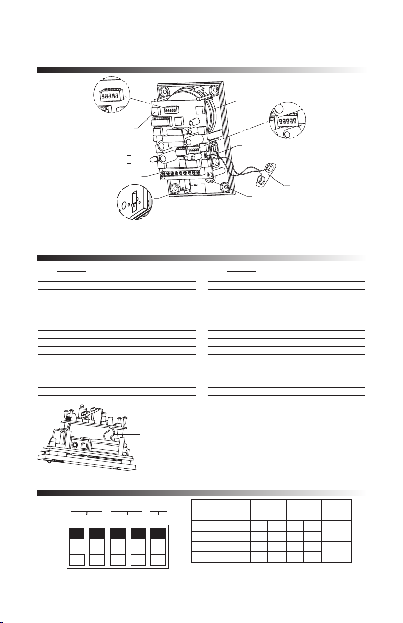
Alarm Electronic Setup ............................................................................page 5
Alarm Tones ............................................................................................page 5
Alarm Timing and Volume ......................................................................page 5
Alarm Terminal Strip Connections ..........................................................page 6
Alarm Electronics Assembly ....................................................................page 6
Assembly Parts ist ................................................................................page 7
Operation ................................................................................................page 7
Warranty ..................................................................................................page 7
Accessories & Replacement Parts............................................................page 8
CO TE TS
WAR I GS
CLEA I G
All units are recommended for indoor use. Unit must be tested periodically to
verify the life of battery. STI recommends you change the 9 Volt battery twice
a year. When purchasing a siren/strobe alarm, you will need to periodically
test the connections to make sure audibles function at a sound level to alert
staff. Installer may need to purchase a simple audio-meter, typically available
at your local electronics store, to measure the sound in areas where the alarm
is expected to be heard during normal noise environment. Results from this
test may prove it beneficial to purchase additional siren/strobe alarm units.
All specifications and information shown are current as of publication and
subject to change without notice.
1. Rinse cover with water to remove abrasive dust and dirt.
2. Wash with soap or mild detergent using a soft cloth. (DO NOT SCRUB.)
3. Rinse once more, then dry with a soft cloth or chamois.
4. To remove grease or wet paint, rub gently with a cloth wetted thoroughly
with naphtha, then wash and rinse. (DO NOT USE RAZOR B ADES.)

DIME SIO S
3
SPECIFICATIO S
OPERATI G VOLTAGE Internal power 9 VDC battery (not included)
Remote power 12-30 VDC
OPERATI G TEMPERATURE 32°F -120°
POWER CO SUMPTIO Stand by: 50µA
Siren low volume: 85mA
Siren high volume: 90mA
Strobe: 25mA
SIRE VOLUME ow: 85 dB
High: 100 dB
ALARM TIMI G Independent control for siren and strobe:
15s, 30s, 60s, continuous
LOW BATTERY WAR I G ED flash once every 30 seconds
FORM C DRY CO TACTS 0-30VAC/DC, 1 Amp
RATED FOR Contacts reset after longest alarm setting
KEY SWITCH Alarm on: normally closed
ALARM SWITCH Stand by: normally open contact required
POLYCARBO ATE U 94V-2
FLAMMABILITY RATI G
FRONT R.H. SIDE
4.31 in.
(109mm)
33.75 in.
(857mm)
19.75 in.
(502mm)
24.75 in.
(629mm)
7.31 in.
(186mm)

4
STEP 1 - MOU TI G OPTIO S
INSTALLATION OF ALARM
O
DRILL
3-/16 DIA HOLES
19018 ANCHOR
#8-10
(2) PROVIDED
19039 SCREW
#6 x 1 1/4 in.
(2) PROVIDED
BASE PLATE
18074 SWITCH LOCK
SUB-SA505 KEY SWITCH
MOUNTING BRACKET
3 9/32 in.
18075 REPLACEMENT
#801 KEY
O
TOKEY MOU T PLATE OR I TO WALL WITHOUT ELECTRICAL BOX
ENCLOSURE
ROUTE THE TWO KEY
SWITCH WIRES THROUGH
THE HOLE AS SHOWN
WIRE ACCESS HOLE
ROUTE THE TWO REED
SWITCH WIRES FROM
CABINET THROUGH THE
HOLE AS SHOWN
E
I STALLATIO OF CABI ET
ote: Installation of cabinet should be before installation of alarm
because the mounting bracket butts up to cabinet.
1. Insert the (4 or 6) mounting tabs fully
into backbox mounting tab slots. Use
rubber mallet if necessary.
2. After selecting a suitable location,
place cabinet in closed position,
against the wall. Mark and
drill (4 or 6) 1/4 in.
diameter holes. Insert the
(4 or 6) 19033 anchors.
Mount cabinet by
driving in the four or six
#10 x 1 1/2 in. screws.
3. For AED model install shelf, close
and lock cabinet.
04876
MOUNTING
PLATE OPTIONAL
TAB
MOUNTING
LOCATION
19033 ANCHOR
(6) PROVIDED
19002 SCREW
#8-32 x 3/8 in.
(4) PROVIDED
6297550
GASKET
19013 SCREW
#10 x 1 1/2 in.
(6) PROVIDED
06298 MOUNTING TABS
(6) PROVIDED
07550WR WIRE
SHELF ON AED
MODELS (ADJUSTABLE) ROTARY ACTION
LATCH (2) PROVIDED
SHOWN WITH
COVER CLOSED
07551WR WIRE RACK
(INCLUDED WITH
AED MODEL)
19002 #8-32 x 3/8 in.
SCREWS AND (4) 19055
#8-32 KEPS NUTS PROVIDED

5
1 0 0 0 0 0 BUZZ
2 1 0 0 0 0 SLOW ON/OFF
3 0 1 0 0 0 SLOW SI EN
4 1 1 0 0 0 3 BEEP/PAUSE/ EPEAT
5 0 0 1 0 0 UFO FAST
6 1 0 1 0 0 FAST SI EN
7 0 1 1 0 0 #5 FAST
8 1 1 1 0 0 #2 MEDIUM
9 0 0 0 1 0 #5 MEDIUM
10 1 0 0 1 0 SWOOP MEDIUM
11 0 1 0 1 0 #3 MEDIUM
12 1 1 0 1 0 BUZZ TONE
13 0 0 1 1 0 STEADY FAST
14 1 0 1 1 0 SWOOP SLOW
15 0 1 1 1 0 CONTINUOUS
16 1 1 1 1 0 FAST EPEAT
17 0 0 0 01 STANDA D ALA M
18 1 0 0 0 1 #3 FAST
19 0 1 0 0 1 #5 SLOW
20 1 1 0 0 1 FAST BEEP
21 0 0 1 0 1 SOUND A
22 1 0 1 0 1 SOUND B
23 0 1 1 0 1 SOUND C
24 1 1 1 0 1 SOUND D
25 0 0 0 1 1 SOUND D LOUD
26 1 0 0 1 1 SOUND E
27 0 1 0 1 1 SOUND F
28 1 1 0 1 1 SOUND G
29 0 0 1 1 1 SOUND H
30 1 0 1 1 1 #4 LOW
31 0 1 1 1 1 SOUND K
32 1 1 1 1 1 CONTINUOUS FAST
1
ALARM TIMING VOLUME
STROBE TIMING
ON
OFF
1
2345
0
15 seconds 11 11 High
30 seconds 10 10 1
60 seconds 01 01 ow
Continuous 00 00 0
1 = O 0 = OFF
STEP 3 - ALARM TO ES - S1
STEP 4 - ALARM TIMI G A D VOLUME - S2
S1
ALARM TONE
S2
ALARM TIMING
STROBE TIMING
VOLUME
LED QTY 10
LOW BATTERY
INDICATOR LED
TERMINAL STRIP
TAMPER SWITCH
(REAR VIEW)
WIRE ENTRY
BATTERY
BATTERY CABLE
SIREN
O
O
1 2 3 4 5 1 2 3 4 5
ALARM
TIMING 1 2 3 4 5
VOLUME
STROBESIREN
*Factory default settings
*
*
STEP 2 - ELECTRO IC SETUP - SELECT ALARM TO E
A D TIMI G SEQUE CE
OTE: Select-Alert must be on a flat surface and lens must be
installed or the tamper switch will trigger the alarm.
OTE: Sound may be disabled by clipping wires to
the siren. THIS WI VOID A WARRANTIES.
Remove two screws on circuit board; leave
enough length of wire to possibly reattach in
the future. Then insulate wires to prevent
shorting to electronic components.
O
O
WI ES TO SI EN

6
N
backbox mounting tab slots. Use rubber
mallet if necessa
in closed position, against the wall. Mark and
drill (4) 1/4 in. diameter holes. Insert the (4)
19033 anchors.
3
inst
through the access hole at See
view Close and lock cabinet.
4
wires are not pinched between the wall and cabinet.
Drive in the (4) screws. Cabinet is now secure.
I
of cabinet. Select at least two
optional mounting holes. Mark and drill 3/16 in.
diameter holes and inst
mounting plate and the siren backplate. Nex
drive the (2) alarm mounting screws into the
previous inst
the terminal sw
screws and provided tool.
1
05050- LENS COLORS
A - AMBER
B - BLUE
G - GREEN
R - RED
W - WHITE
19002 SCREW
#8-32 x 3/8 in.
(4) PROVIDED
ELECTRONICS
INSTALLED
BASE PLATE
WIRE ACCESS HOLE
19016 TAMPER-PROOF
TOOL (1) PROVIDED
19011 TAMPER-PROOF
SCREW
ROUTE WIRES
THRU HOLE
STEP 5 - ELECTRO ICS ASSEMBLY
Wiring: After mounting circuit board assembly, connect wires. Refer to terminal strip connections (step 6).
Lens installation: Slide lip of lens behind circuit board mounting plate. Rotate lens into position. Secure with
tamperproof screw and special wrench. Unit will not operate properly if lens cover is not installed.
STEP 6 - TERMI AL STRIP CO ECTIO S
O
REMOTE POWER IN
12-30 VDC, 125mA
(OPTIONAL)
+-OFF ON
MAIN POWER
CONTROL TO
KEY SWITCH
STAND
BY
REED
SWITCH FROM CABINET
FORM "C"
DRY CONTACTS
NORMALLY OPEN
COM
+-
DCIN
KEY
SWITCH
ALARM
SWITCH
NC
COM
NO
NORMALLY CLOSED
ACTIVE
OTE: “DC IN” are the only
polarity sensitive terminals.
When external power is
used, battery will act as a
backup. “Dry Contacts: NC,
COM, NO” are used for
remote alarm monitoring.
!

7
STEP 7 - OPERATIO
• Turn key switch on to arm.
• Cycle key switch to reset alarm.
• Alarm will sound when cabinet is opened (alarm switch is electronically
closed), alarm cover is removed or unit is removed from the wall.
• To service, turn key switch off.
WARRA TY I FORMATIO
ifetime guarantee against breakage of polycarbonate housing (one year on
electronics).
ASSEMBLY PARTS LIST
1 05000 Electronics assembly (includes base plate & electronics assembly)
1 05050- ed lens (unless otherwise specified)
1 09723 Key switch mounting bracket
2 18075 #801 key
1 18074 Switch lock
1 18151 N.C. reed switch and magnet (installed in cabinet)
4 19002 Screw #8-32 x 3/8 in.
2 19039 Screw #6 x 1 1/4 in.
2 19018 Anchor #8-10
1 19011 #8-32 x 1/2 in. tamper screw
1 19016 Tamper wrench
1 BAT-9VDC 9 volt battery
SIRE /STROBE ALARM
CABI ET
1 07550 Hinged polycarbonate enclosure
6 06298 Mounting tabs
6 19013 #10 x 1 1/2 in. screw
6 19033 Plastic anchor
1 07550W Wire shelf (Included with AED models only)
1 07551W Wire rack (Included with AED models only)
1 04876 Mounting plate
4 19002 #8-32 x 3/8 in. screw
1 6297550 Gasket
1 07503 Thumb lock - STI-7555 models
1 18050 Key lock
2 18054 CH751
}
STI-7554 models
QTY. PART # DESCRIPTION

Printed in USA Inst. Sht. STI-7554/STI-7555AED, DEC2010
Safety Technology International, Inc.
2306 Airport Road
Waterford, Michigan 48327-1209
Phone: 248-673-9898 • Toll Free: 800-888-4784 • Fax: 248-673-1246
Safety Technology International (Europe) Ltd.
Unit 49G Pipers Road • Park Farm Industrial Estate • Redditch
Worcestershire • B98 0HU • England • Tel: 44 (0) 1527 520 999
Fax: 44 (0) 1527 501 999 • Freephone: 0800 085 1678 (UK only)
E-mail: [email protected] • Web: www.sti-europe.com
ACCESSORIES A D REPLACEME T PARTS
AED-LBL Optional AED label - 2 included (applied to
sides of cabinet; must be factory installed)
STI-SA5000-R Replacement Siren/Strobe Alarm
18054 Replacement key for cabinet lock on STI-7554
18075 Replacement key for Siren/Strobe Alarm
07550WR Wire shelf (included with AED models)
07551WR Wire rack (included with AED models)
This manual suits for next models
2
Table of contents
Other STI Protection Device manuals

STI
STI Euro Stopper STI-15000 Series User manual

STI
STI 6529 User manual

STI
STI UM Series User manual

STI
STI STI-6514 User manual

STI
STI STI-7560AC User manual

STI
STI 13000 Series Instruction sheet

STI
STI SA5500 User manual

STI
STI Euro Stopper STI-15000 Series User manual

STI
STI STI-13000 Series Instruction sheet