manuals.online logo
Brands
  1. Home
  2. •
  3. Brands
  4. •
  5. TELE
  6. •
  7. Protection Device
  8. •
  9. TELE ENYA Series User manual

TELE ENYA Series User manual

E1ZMLA10 24-240V AC/DC
www.tele-online.com
Load Alternator + Timer
ENYA series
5 functions
7 time ranges
Wide input voltage range
1 change over contact
Width 17.5 mm (0.69 in)
Installation design
Technical data
1. Functions
The funktion can be selected at anytime if connected to the supply
voltage.
E ON delay
R OFF delay
L1 Manual OFF
LA Load Alternator (Pump Changer)
L2 Manual ON
2. Time ranges
Time range Adjustment range
1 s 50 ms 1 s
10 s 500 ms 10 s
1 min 3 s 1 min
10 min 30 s 10 min
1 h 3 min 1 h
10 h 30 min 10 h
100 h 5 h 100 h
3. Indicators
Green LED U/t ON: indication of supply voltage
Green LED U/t flashes: indication of time period
Yellow LED R ON/OFF: indication of relay output
4. Mechanical design
Self-extinguishing plastic housing, rated IP40.
Mounted on DIN-rail TS 35 according to EN 60715
Mounting position: any
Shockproof terminal connection according to VBG 4 (PZ1 required).
Terminals are rated IP20
Tightening torque: max. 1 Nm (0.74 ft lbs)
Terminal capacity:
1 x 0.5 to 2.5 mm² (1 x 20 to 14 AWG)
with/without multicore cable end
1 x 4 mm² (1 x 12 AWG)
without multicore cable end
2 x 0.5 to 1.5 mm² (2 x 20 to 16 AWG)
with/without multicore cable end
2 x 2.5 mm² (2 x 14 AWG)
flexible without multicore cable end
5. Input circuit
Supply voltage: 24 to 240V a.c./d.c.
Terminals: A1(+)-A2
Tolerance: 24V -15% to 240V +10%
Rated consumption: 4VA (1.5W)
Rated frequency: a.c. 48 to 63 Hz
Duty cycle: 100 %
Reset time: 100 ms
Residual ripple for d.c.: 10 %
Drop-out voltage: >30 % of minimum rated supply voltage
Overvoltage category: III (in accordance with IEC 60664-1)
Rated surge voltage: 4kV
6. Output circuit
1 isolated change over contact (1 CO)
Contact material: AgNi
Rated voltage: 250V a.c.
Switching capacity: 2000VA (8A / 250V a.c.)
Fusing: 8A fast acting
Mechanical life: 20 x 106operations
Electrical life: 1 x 10⁵operations
at 1000VA resistive load
Switching frequency: max. 6/min at 1000VA resistive load
(in accordance with IEC 60947-5-1)
Overvoltage category: III (in accordance with IEC 60664-1)
Rated surge voltage: 4kV
7. Control input
Input not potential free: terminals A1-B1
Loadable: yes
Max. line length: 10 m
Trigger level (sensitivity): automatic adaption to supply voltage
Min. control pulse length: d.c. 50 ms / a.c. 100 ms
8. General data
Degree of protection: Basic insulation
Insulation test voltage:
Supply circuit - Output circuit: 1680V
Interference immunity: Class A
Prospective current value: 1000A / 8A
8. Accuracy
Base accuracy: ±1 % of maximum scale value
Adjustment accuracy: <5 % of maximum scale value
Repetition accuracy: <0.5 % or ±5 ms
Voltage influence: -
Temperature influence: ≤0.01 % / °C
9. Ambient conditions
Ambient temperature: -25 to +55 °C (-13 to +131 °F)
Storage temperature: -25 to +70 °C (-13 to +158 °F)
Transport temperature: -25 to +70 °C (-13 to +158 °F)
Relative humidity: 15 % to 85 %
(in accordance with IEC 60721-3-3
class 3K3)
Pollution degree: 2 (in accordance with IEC 60664-1)
10. Weight
Single packing: 80 g (2.82 oz)
E1ZMLA10 24-240V AC/DC
www.tele-online.com
OFF delay (R)
The supply voltage U must be constantly applied to the device (green
LED U/t illuminated). When the control contact S is closed, the output
relay R switches into on-position (yellow LED illuminated). If the control
contact is opened, the set interval t begins (green LED ashes). After
the interval t has expired (green LED U/t illuminated) the output relay
switches into o󰀨-position (yellow LED not illuminated). If the control
contact is closed again before the interval t has expired, the interval
already expired is erased and is restarted.
Functions
Load Alternator - Pump Changer (LA)
In this mode, every falling edge toggles the output relay R (ip-op) from
L1 to L2 or L2 to L1 whatever position is dened by the previous status.
On Power-Up the relay R stays in o󰀨 condition until the rst falling edge is
detected on S Terminal B1.
To ensure a safe and optimal function, please turn both timing controllers
on the front to the most left position (CCW), which equals 50 msec.
In this operation mode, a minimum delay/de-bump time of 50 msec is
applied from the falling edge of the control input until relay R is changing
its state.
Is a longer delay time as 50 msec is set, a short pulse on the „S“ input
resets the times. The timer is restarted with the next falling edge signal on
„S“ input again. If you wish to apply longer delay times, set the according
time selectors to the required values or contact your application engineer.
Manual OFF (L1)
If the function selector indicates function L1, the output relay R remains
in the o󰀨-position. If you switch from LA to L1 the relay switches into
o󰀨-position independent of the status of the control input.
Manual ON (L2)
If the function selector indicates function L2, the output relay R remains
in on-position as long as the supply voltage is available. If you switch
from LA to L2 the relay switches into on-position independent of the
status of the control input.
ON delay (E)
When the supply voltage U is applied, the set interval t begins (green
LED U/t ashes). After the interval t has expired (green LED U/t
illuminated) the output relay R switches into on-position (yellow LED
illuminated). This status remains until the supply voltage is interrupted.
If the supply voltage is interrupted before the expiry of the interval t,
the interval already expired is erased and is restarted when the supply
voltage is next applied.
U
U/t
S
R
LED
<t
t
<t
U
U/t
R
LED
<t
t
E1ZMLA10 24-240V AC/DC
www.tele-online.com
Dimensions
Connections
with control input
OFF Delay (R)
without control input
ON Delay (E)
Load Alternator - Pump Changer (LA)
A1
B1
15
A2
16
18
A1
R
1
5
16
18
U~
(+)
(-)
A2
S
A1
B1
15
A2
16
18
A1
R
1
5
16
18
U~
(+)
(-)
A2
Ordering information
Type Functions Supply voltage Art. No.
E1ZMLA10 24-240V AC/DC E, R, LA, L1, L2 24-240V a.c. / d.c. 110218
TELE Haase Steuergeräte Ges.m.b.H.
Vorarlberger Allee 38
AT-1230 Vienna, AUSTRIA
RELEASE 2019/11
Subject to alterations and errors
This device is subject to the Waste Electrical and Electronic Equipment Regulation (WEEE) and may not be disposed of with normal domestic
waste. The device is made of materials that can be recycled by specialized recycling companies. The device must be disposed of according to
the national electronic scrap regulations.

This manual suits for next models

2

Other TELE Protection Device manuals

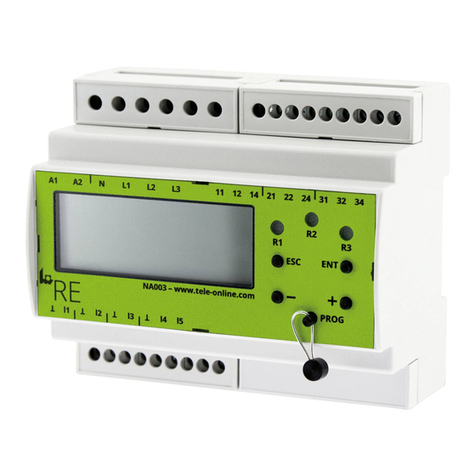
TELE NA003-M64 User manual

TELE

TELE NA003-M64 User manual

TELE RE-NA003 User manual

TELE

TELE RE-NA003 User manual

TELE Re NA003 User manual

TELE

TELE Re NA003 User manual

TELE NA003-M64 User manual

TELE

TELE NA003-M64 User manual

Popular Protection Device manuals by other brands

StressVest SUICIDE VEST Quick setup guide

StressVest

StressVest SUICIDE VEST Quick setup guide

Sundstrom SR 905 operating instructions

Sundstrom

Sundstrom SR 905 operating instructions

Engelbert Strauss 84688 Instructions and information

Engelbert Strauss

Engelbert Strauss 84688 Instructions and information

Simco-Ion Performax Easy Speed user manual

Simco-Ion

Simco-Ion Performax Easy Speed user manual

Trend Micro TippingPoint TPS TX Series Hardware Specification and Installation Guide

Trend Micro

Trend Micro TippingPoint TPS TX Series Hardware Specification and Installation Guide

LEGRAND 0 288 03 manual

LEGRAND

LEGRAND 0 288 03 manual

DBI SALA Sayfline Multi-span Wire Rope Horizontal... User instruction manual

DBI SALA

DBI SALA Sayfline Multi-span Wire Rope Horizontal... User instruction manual

Intermatic IG1201F20 installation instructions

Intermatic

Intermatic IG1201F20 installation instructions

Panasonic NA40 Series instruction manual

Panasonic

Panasonic NA40 Series instruction manual

Novus NVS-021VPSD-HD user manual

Novus

Novus NVS-021VPSD-HD user manual

TSG 710210 owner's manual

TSG

TSG 710210 owner's manual

Horizont 15498C Operating	 instruction

Horizont

Horizont 15498C Operating instruction

MTE dV Sentry installation guide

MTE

MTE dV Sentry installation guide

Guardian LINGO Quick start user guide

Guardian

Guardian LINGO Quick start user guide

RMS 1S20-FAB manual

RMS

RMS 1S20-FAB manual

MSA OptiVizor Instructions for use

MSA

MSA OptiVizor Instructions for use

Arcteq AQ-G3 7 Series instruction manual

Arcteq

Arcteq AQ-G3 7 Series instruction manual

ABB RED615 ANSI Product guide

ABB

ABB RED615 ANSI Product guide

manuals.online logo
manuals.online logoBrands
  • About & Mission
  • Contact us
  • Privacy Policy
  • Terms and Conditions

Copyright 2025 Manuals.Online. All Rights Reserved.