STI STI-6514 User manual

2306 Airport Road • Waterford, Michigan 48327-1209
Phone: 248-673-9898 • Fax: 248-673-1246
Toll Free: 800-888-4784 • E-mail: [email protected]
Web: www.sti-usa.com
Taylor House • 34 Sherwood Road • Bromsgrove
Worcestershire • B60 3DR • England
Tel: +44 (0)1527 520 999 • Fax: +44 (0)1527 501 999
E-mail: [email protected] • Web: www.sti-emea.com
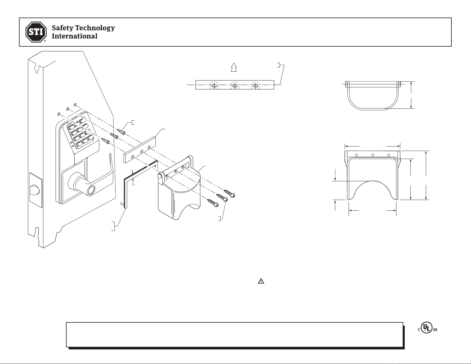
INSTALLATION OF STI-6514 PROTECTIVE COVER
All specifications and information shown were current as of publication and are subject to change without notice.
INSTALLATION NOTES
1. Cut out template and place it around unit as shown.
2. Remove backing paper from gasket, install gasket around
template with surface “A” lying directly above the template,
discard template.
3. Using spacer as drill template mark and drill three (3) 3/16 in.
diameter holes. Complete installation as shown.
OPTIONAL: If anchors are not required, use spacer as template,
mark and drill (3) holes using a #32 drill bit.
BIO6514 AUG2008
CLEANING INSTRUCTIONS
Rinse with water to remove abrasive dust and dirt. Wash
with soap or mild detergent using a soft cloth. DO NOT
SCRUB OR USE BRUSHES OR ABRASIVES. Rinse once more,
then dry with a soft cloth or chamois. To remove grease or
wet paint, rub gently with a damp cloth thoroughly with
naphtha. Then wash and rinse. DO NOT USE RAZOR BLADES.
FRONT VIEW SIDE VIEW
3.60 in.
(91mm)
2.56 in.
(65mm)
3.75 in.
(95mm)
2.97 in.
(75mm)
M1015980 HINGE SPACER
COVER ASSEMBLY
G405440 NEOPRENE
GASKET
CENTER LINE
OF SPACER
UP
MAKE SURE SPACER IS
INSTALLED AS SHOWN WITH
MOUNTING HOLES BELOW CENTER LINE.
SPACER ORIENTATION
SURFACE
“A”
TEMPLATE
ANCHOR
(3) PROVIDED
MOUNTING SCREW
6 x 1 1/4 in.
(3) PROVIDED
WARNING: This product can expose you to chemicals including Dichloromethane, which is
known to the State of California to cause cancer, and Bisphenol A (BPA), which is known to the
State of California to cause birth defects or other reproductive harm.
For more information go to www.P65Warnings.ca.gov.
Three year warranty or a one year limited warranty (from date of purchase) on most products.
See website for details. Electronic warranty form at www.sti-usa.com/wc14.
2306 Airport Road • Waterford, Michigan 48327-1209
Phone: 248-673-9898 • Fax: 248-673-1246
Toll Free: 800-888-4784 • E-mail: [email protected]
Web: www.sti-usa.com
Taylor House • 34 Sherwood Road • Bromsgrove
Worcestershire • B60 3DR • England
Tel: +44 (0)1527 520 999 • Fax: +44 (0)1527 501 999
E-mail: [email protected] • Web: www.sti-emea.com
INSTALLATION OF STI-6516 MINI BOPPER STOPPER®
All specifications and information shown were current as of publication and are subject to change without notice.
INSTALLATION NOTES
1. Remove backing paper and center gasket (G82599) left to right
around lock with surface “B” against top of lock.
2. Next center spacer M1015980 with bottom of spacer lying on
surface “A” of gasket.
3. Using spacer as template, mark and drill three (3) 3/16 in. DIA.
holes. Complete assembly as shown.
Optional: if anchors are not required use spacer as template,
mark and drill (3) holes using a # 36 drill size.
6516IS MAY2006
CLEANING INSTRUCTIONS
Rinse cover with water to remove abrasive dust
and dirt. Wash with soap or mild detergent using
a soft cloth. (DO NOT SCRUB.) Rinse once more,
then dry with a soft cloth or chamois. To remove
grease or wet paint, rub gently with a cloth
wetted thoroughly with naphtha, then wash and
rinse. (DO NOT USE RAZOR BLADES.)
ADA
Compliant
ADA
Compliant
SCHLAGE
3.25 in.
(82mm)
3.625 in.(92mm)
1.5 in.
(38mm)
TOP VIEW
FRONT VIEW
3.75 in.(95mm)
2 in.(51mm)
COVER ASSEMBLY
GASKET
(ADHESIVE BACKING
TOWARD DOOR)
COVER ASSY.
SPACER
ANCHOR
(3) PROVIDED
SURFACE
“A”
SURFACE
“B”
SCREWS #6 x 1 1/4 in.
(3) PROVIDED
ANCHOR
(3) PROVIDED
M1015980 SPACER
KIT-G82599 GASKET
(ADHESIVE BACKING
TOWARD DOOR)
SURFACE
“A”
SURFACE
“B”
SCREWS #6 x 1 1/4 in.
(3) PROVIDED
3.25 in.
(82mm)
3.625 in.(92mm)
1.5 in.
(38mm)
TOP VIEW
FRONT VIEW
3.75 in.(95mm)
2 in.(51mm)
4 in.
(102mm)
4 in.
(102mm)
CENTER LINE
OF SPACER
UP
MAKE SURE SPACER IS
INSTALLED AS SHOWN WITH
MOUNTING HOLES BELOW CENTER LINE.
SPACER ORIENTATION
WARNING: This product can expose you to chemicals including Dichloromethane, which is
known to the State of California to cause cancer, and Bisphenol A (BPA), which is known to the
State of California to cause birth defects or other reproductive harm.
For more information go to www.P65Warnings.ca.gov.
Three year warranty or a one year limited warranty (from date of purchase) on most products.
See website for details. Electronic warranty form at www.sti-usa.com/wc14.
Other STI Protection Device manuals

STI
STI Euro Stopper STI-15000 Series User manual

STI
STI STI-7554 User manual

STI
STI STI-7560AC User manual

STI
STI UM Series User manual

STI
STI SA5500 User manual

STI
STI 6529 User manual

STI
STI STI-13000 Series Instruction sheet

STI
STI Euro Stopper STI-15000 Series User manual

STI
STI 13000 Series Instruction sheet


