Rayco C120R 2019 User manual

C120R
PARTS MANUAL
RAYCO MANUFACTURING © 2019 ALL RIGHTS RESERVED
PRINTED IN USA
INDEX: PMC120R-19

C120R PARTS MANUAL
2
This manual is published by Rayco Manufacturing, Inc. for the
benefit of the users of Rayco products. Rayco Manufacturing,
Inc. has made every effort to ensure that this manual is
correct and up to date at the time of publication. However,
due to continuous improvements, Rayco Manufacturing, Inc.
reserves the right to make changes in the contents, at any
time, without notice or obligation.
Each machine shipped contains operation, maintenance
& parts manuals to familiarize the operator with the proper
operating, lubricating and maintenance instructions. This
helps to ensure the best possible performance and service
from the machine. Read and understand all instructions before
attempting to operate this machine. This manual should be
readily available for reference at all times. Additional copies
of this manual may be purchased from Rayco.
This Rayco machine was designed and manufactured by
Rayco Manufacturing, Inc., Wooster, Ohio. Due to continuous
improvements, Rayco reserves the right to make changes
in engineering, design and specifications, or discontinue
manufacture, at any time, without notice or obligation.
NOTICE:
Maintenance and Repairs should ONLY be performed by a trained
specialists or qualified person.
Please contact Rayco Mfg for a listing of approved maintenance facilities in your area.
Contents
CALIFORNIA PROPOSITION 65
WARNING THIS MACHINE AND ITS
CONSTIUENTS ARE KNOWN IN THE STATE
OF CALIFORNIA TO CAUSE CANCER AND
REPRODUCTIVE HARM.
VISIT WWW.P65WARNINGS.CA.GOV

C120R PARTS MANUAL
800.392.2686 3
Content
Literature Information
The operators manual should be stored in the operator’s
compartment in the literature holder storage area. Rayco
provides a binder to hold the Operator Service Manual, Parts
Manual, Engine Manual along with other component manuals.
These manuals contain safety information, operation
instruction, transportation information, lubrication information
and maintenance information.
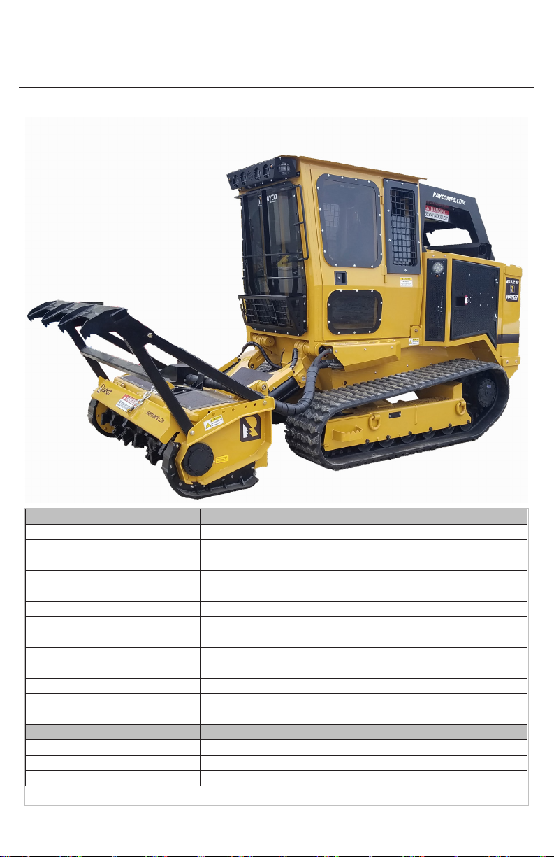
Some photographs or illustrations in the publication show
details of attachments that can be different from your machine.
Guards and covers might have been removed for illustrative
purposes. Continuing improvementmay have caused changes
to your machine which may not be included in this publication.
Continuing improvement and advancement of product
design might have caused changes to your machine which
are not included in this publication. Read, study and keep
this manual with the machine.
Whenever a question arises regarding your machine, of this
publication, please consult your Rayco dealer for the latest
available information.
Safety
The safety section lists basic safety precautions. In addition,
this section may include text and locations of warning signs
and labels used on the machine.
Read and understand the basic precautions listed in the
safety section before operating or performing lubrication,
maintenance and repair on this machine.
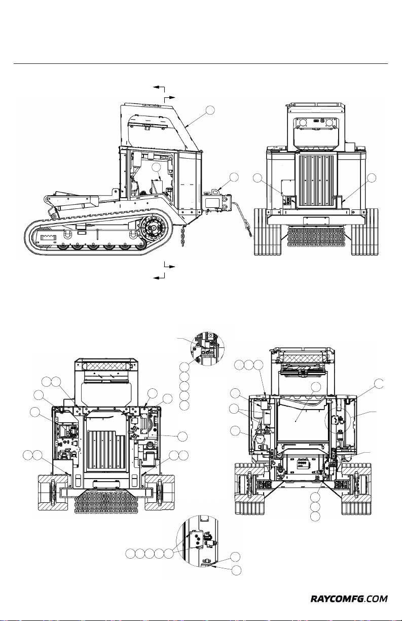
Parts
Parts are readilyfound through illustrations with accompanying
Rayco part numbers. The machine assembly is listed by basic
groups to enable ease of finding parts.
Please consult your local Rayco Dealer or local Engine
Manufacturer Dealer for obtaining engine parts and service.
Operation
The operation section is a reference for the new operator
and a refresher for the experienced operator. This section
includes a discussion of gauges, switches, machine controls,
attachment controls, transportation and towing information.
Photographs and illustrations guide the operator through
correct procedures of checking, starting, operating and
stopping the machine.
Operating techniques outlined in this publication are basic.
Skill and techniques develop as the operator gains knowledge
of the machine and its capabilities.
Maintenance
The maintenance section is a guide to equipment care.
The Maintenance Interval Schedule lists the items to be
maintained at a specific service interval. The Maintenance
Interval Schedule lists the page number for the step-by-
step instructions required to accomplish the scheduled
maintenance procedure.
Maintenance Intervals
Use the service hour meter to determine servicing intervals.
Calendar intervals shown (daily, weekly, monthly, etc.) can be
used instead of service hour meter intervals if they provide
more convenient servicing schedules and approximate the
indicated service hour meter reading. Recommended service
should always be performed at the interval that occurs first.
Under extremely severe, dusty or wet operating conditions,
more frequent lubrication than is specified in the maintenance
intervals chart might be necessary.
Perform service on items at multiples of the original
requirement. For example, at every 100 service hours, also
service those items listed under every 50 service hours and
every 10 service hours or daily.

C120R PARTS MANUAL
4
Information
A Description of the Machine
The C120R is an evolution of Rayco’s purpose-built mulcher
line. With features such as a 121hp diesel engine, large
cab with side-entry door, impressive mulcher lift height. The
C120R is ideal for those who want a powerful mulcher in a
compact chassis. The C120R has an overall width of just
83-inches, and weighs in at 15,900lbs including the mulcher
making it easy to transport and nimble enough for operation
on jobs where larger mulchers just don’t work.
The C120R rides on rubber tracks with 2-speed travel. The
rubber track design promotes longer track life and smooth
operation by reducing debris packing in the track chain and
keeps the drive components out of the hi-impact areas.
Powerful final drives provide torque for climbing hills and allow
the C120R to maneuver easily in difficult terrain.
Because it’s purpose-built, the C120R is loaded with features
operators appreciate. The spacious cab is equipped with
a heated, air-ride suspension seat, and the rear fan is auto-
reversing, reducing maintenance time. All gauges and
controls are located on a large LCD display that includes
a rearview camera.

C120R PARTS MANUAL
800.392.2686 5
Information
Machine Specs
GENERAL DATA US METRIC
Weight With Winch And Mulcher 15,900LBS 7,212KG
Length With Mulcher 199.6IN 507CM
Height 102IN 259.1CM
Width 83.6IN 212.4CM
Engine 121HP CAT TIER 4
Fuel Type DIESEL
Ground Pressure With Mulcher 5.65PSI 38.9KPA
Travel Speed - Fast Track/Travel/Work 7/4.7/2.6MPH 11.2/7.5/4.1KPH
Mulcher Head - Standard FM120-6R
Overall Width 83 IN 210.8 CM
Cutting Width 71.5 IN 181.6 CM
Rotor Diameter 16.75 IN 42.5 CM
Teeth 36 36
Hydraulic System
LO FLOW OPEN LOOP 20GPM 3,770PSI 75.7LPM 25,993KPA
HI FLOW OPEN LOOP 40GPM 3,770PSI 151.4LPM 25,993KPA
SUPER FLOW 52GPM 5,076PSI 196.8LPM 34,997.8

C120R PARTS MANUAL
6
Serial Number Location & Information
Always have a record of the model numbers and serial numbers for your machine to specify when ordering parts. Record
your machine model and serial numbers below for your personal records.
Serial number is located as shown.
Use the below table to record identification numbers and dealer information.
Serial Numbers Location
Whenever communicating with Rayco or your Rayco dealer, have your machine serial number handy, as it can help pinpoint
most exactly what information is needed in caring for your machine.
Breakdown of the serial number
For Example: C120R 001 01 19
C120R - Type of Rayco equipment you have
001 - Three digit for the number of produced
02 - Two digit month, 01 = Jan., 02 = Feb., etc...
19 - Two digit year, 19 = 2019, 20 = 2020, etc
It is attached to the machine at the location shown. For ready reference, record it in the boxes provided on the next page
of this manual.
For reference on communication regarding the engine, record its model and serial numbers also in the boxes provided on
the inside front cover of this manual. See the Engine Operator Manual for assistance in locating the numbers on the engine.
C120R
C120R 0010119
39568
15900/7212(kg)
2019
121HP (90kw)
CRAWLER
001= The three digit number of produced
C120R = Type of Rayco Equipment Production Date; 01=2 digit month; 15= 2 digit year

C120R PARTS MANUAL
800.392.2686 7
Serial Number Location & Information
Identification Numbers
Model Number Serial Number
Machine
Engine
Implement
Implement
Dealer Information
Name
Address
Dealer Contact Phone Number Hours
Sales
Parts

C120R PARTS MANUAL
8
Main Frame Assembly 39113 Rev A
G
F
SECTION A-A
19
7
22
12
DETAIL G
SCALE 2 : 15
59
48
47
68
44 66
CONTROL VALVE INCLUDED
WITH 805860 ENGINE
21
HARNESS GROUNDING POINT
DETAIL F
SCALE 2 : 15
72 48 47 30 33
18
HARNESS GROUNDING POINT
A
A
B
B
D
C
23
33
27
17
6553
EE
9
10
16
26
DETAIL D
SCALE 2 : 15
582833 27
DETAIL C
SCALE 2 : 15
54
25

C120R PARTS MANUAL
800.392.2686 9
H
P
SECTION B-B
25
15
3
2
41
45 5 3
41 33 1
41 33 1
31
11
29
24
9
17
33
46
DETAIL H
SCALE 2 : 15
42
33
67
49
HARNESS GROUNDING POINT
60
61
54
DETAIL P
SCALE 1 : 4
43
50
49
HARNESS GROUNDING POINT
Main Frame Assembly 39113 Rev A
J
SECTION E-E
22
21
25 29 11
9
26
15
24
38
DETAIL J
SCALE 1 : 6
72 48 47 30

C120R PARTS MANUAL
10
SECTION L-L
16
31
54
10
57 20
5720
6
6953
M
N
SECTION K-K
32
24
63
40
1
56
33
7
6263
6
DETAIL M
SCALE 2 : 15
6470
71
55
335161
DETAIL N
SCALE 2 : 15
59
48
47
68
8
NOTE: CENTER VALVE
PROVIDED WITH 805893
REVERSING FAN
Main Frame Assembly 39113 Rev A
L
L
K
K
11
23
95252
NOTE: 39036 WINCH HIDDEN
FOR CLARITY

C120R PARTS MANUAL
800.392.2686 11
ITEM QTY. PART # DESCRIPTION
1 2 11543 FILTER ASM, REWORK
2 1 26329 PIN, CAB PIVOT UPR WELD
3 1 26333 CYLINDER, CAB LIFT WELD
4 1 29001 LAMP, W/MAGNET BASE ASM
5 1 33110 PIN, CAB LIFT CYL PIN LOWER
WELD
6 1 34196 CYL BLOCK MNT ASM
7 1 35540 POWER UNIT, HYD 12V REWORK
8 1 38177 VALVE-2POS/3WAY WP
CONNECTOR
9 1 39036 WINCH ASM
10 139067 TANK, HYD ASM
11 1 39236 BATTERY ASM, C120
12 1 39569 HARNESS-WIRING FRAME
13 1 39573 CABLE-BATTERY KIT
14 1 3 9574 TRACK GROUP ASM C120
15 1 39580 SUCTION MANIFOLD ASM C120
16 1 39581 TANK, FUEL ASM
17 139596 DEBRIS CHAIN ASM C120
18 1 39600 RETURN MANIFOLD ASSEMBLY
19 1 39604 PVG VALVE W/ MOUNT ASM C120
20 2 39607 CVR, UNDER TANKS C120
21 1 39619 TRANSDUCER ASM C120
22 1 39622 FRAME FUSE RELAY ASM
23 1 39636 LIMB RISER ASM C120
24 1 39656 PUMP ASM, HYD FILL C120
25 1 39667 MULTICOUPLER ASM, SUPER FLO
C120
26 1 39691 RADIATOR DOOR ASM C120
27 139693 VALVE BLK ASM, LOADER CTRL
C120
28 2 39699 CAP, LOADER ARM PIVOT PIN
HLDR
29 1 3 9741 BATTERY DISCONNECT ASM
30 239746 MANIFOLD, COOLANT
DISTRIBUTION
31 1 39749 DEF CONTROL PANEL ASM
32 1 39753 MID BULKHEAD ASSEMBLY
33 1 39919 FRAME WELDMENT C120
34 139941 PANEL, ACCESS COOLER RET
C120
35 1 39943 PANEL, REAR ACCESS
36 1 40008 CAB LATCH ASM C120
37 1 40026 DEF FLUID SUPPLY MODULE ASM
38 140044 RIGHT SIDE HYD CPLR ASM C120
39 140130 FILTER, RETURN ASM C120
40 2 722110 BOLT WHIZ 1/4-20 X 3/4
41 9 722114 BOLT WHIZ 3/8-16 X 3/4 GR8.2 ZP
42 2 722201 BOLT HEX 5/16-18 X 2 GR8
43 1 722203 BOLT HEX 5/16-18X 3/4 GR8
44 3 722207 BOLT HEX 5/16-18 X 2- 1/2 GR8
45 1 722503 BOLT HEX 1/2-13 x 1 1/4
46 1 724503 NUT-HNML 1/2-13 PREV TORQ GR8
47 6 726101 WASHER FLAT 1/4 USS
48 6 726102 WASHER-LOCK, 1/4”
49 3 726201 WASHER - FLAT 5/16
50 1 726202 WASHER LOCK 5/16” PLATED
51 4 726300 WASHER FLAT 3/8 SAE
52 2 730080 GREASE ZERK 1/8 PTF STR
53 22 750057 NUT-WHIZ 1/2-13 SERR FLANGE L/N
GR8 ZN
54 30 750061 NUT-WHIZ 3/8-16 SERR FLANGE L/N
GR8 ZN
55 2 750118 CLAMP-HOSE 2-5/16”-3-1/4”
56 6750399 BOLT WHIZ 3/8-16 X 1” GR8.2 ZP
57 8 750413 BOLT WHIZ 1/2-13 X 3/4
58 8750769 BOLT WHIZ 3/8-16 X 1/2
59 2750865 BOLT HEX 1/4-20 X 4
60 2 751019 BOLT WHIZ 3/8-16 X 1-1/2
61 4 760261 NUT-HNNL 3/8-16 INS
62 1 761037 FILTER HEAD ZAF-10-25-0
63 1 761038 FILTER-HYD AE-25
64 2 761531 BOLT HEX 3/8-16 X 4 GR8
65 8 761617 BOLT WHIZ 1/2 -13 X 1 1/4” GR8.2
ZP
66 3763757 WASHER FLAT 5/16 HARDENED
67 1 765166 VALVE,CROSS-OVER RELIEF
68 1 800814 VALVE, PRESSURE REDUCING
69 14 802273 BOLT WHIZ 1/2 -13 X 1-1/2”
70 1802768 VALVE- FAN DRIVE STD
SUNSOURCE
71 1 803983 RECEIVER DRIER-3” W/SW &
PIGTAIL
72 4804622 BOLT HEX 1/4-20 X 2 1/2
Main Frame Assembly 39113 Rev A

C120R PARTS MANUAL
12
ITEM QTY. PART # DESCRIPTION
1 1 803264 FILTER-ASM PRESS, 3 PORT,
W/METRIPAK SWITCH
*
*
*
1
NOTE:
1. WIRE CONNECTOR AS FOLLOWS:
WHITE WIRE = POSITION "B"
RED WIRE = POSITION "A"
BLACK WIRE = POSITION "C"
OIL FILTER 762462
Filter Assembly 11543 Rev A

C120R PARTS MANUAL
800.392.2686 13

C120R PARTS MANUAL
14
12 Volt Power Hydraulic Unit 35540
1
7
5
65
4
3
PIN 'A'IN
800928
CONNECTOR
PIN 'B'IN
800928
CONNECTOR
CONNECTOR
804138
PIN 'A' WHITE WIRE
PIN 'B' BLACK WIRE
PIN 'C' GREEN WIRE
PIN 'D' RED WIRE
2
ITEM QTY. PART # DESCRIPTION
1 1 801697 POWER UNIT- HYD 12V ELEC
MOTOR
2 1 801697-
2REMOTE-POWER UNIT, 2 BUTTON
3 1 804138 CONNECTOR-WP FLAT, 4 WAY
FEMALE
4 1 800928 TERMINAL-WEATHER PACK
SOCKET
5 6 761653 TERM-WTHPACK SEAL 18-20
6 2 761424 TERM-WTHPACK M 14-16
7 4 761654 TERM-WTHPACK F 14-16

C120R PARTS MANUAL
800.392.2686 15
Winch Assembly 39036 Rev B
9
13
2
2829
7
12
11
24
19
18
36 19
32
8
17
3
1620
22
30
37
5
6
4
1027
26
25
21
35
2314
33
34
THESE BOLTS BOTTOM OUT
AND ACT AS PIVOTS
THESE BOLTS BOTTOM OUT
AND ACT AS PIVOTS
31 15
WINCH CABLE INSTALLATION (USE TWO PEOPLE FOR SAFETY):
WIND WINCH CABLE SO THAT HOOK END UNWRAPS
1.
FROM BOTTOM SIDE OF WINCH DRUM.
HOLD TENSION AND WRAP CABLE TIGHTLY AND EVENLY
2.
WITH NO GAPS.
ITEM QTY. PART DESCRIPTION
1 2 11630 ROLLER, FAIRLEAD TOP
2 2 19060 WASHER, UHMW 2-1/2” X 1-1/4” X
1/4”
3 2 19978 PIN, FAIRLEAD WELDMENT
4 2 22919 ROLLER, WARN FAIRLEAD SIDE
5 1 28324 BLOCK, STOP WINCH ASM
6 2 28432 PIN, FAIRLEAD WELD
7 1 39037 ENCLOSURE, WINCH WELD
8 1 39073 LINK, SIDE COVER
9 1 39078 WELD, WINCH SIDE COVER
10 139083 WELD, WINCH SIDE COVER RH
11 1 39759 DOOR, TOP WINCH C120
12 1 40206 PIN, REMOVABLE WINCH PIN
WELD
13 1 40208 PIN, WINCH PIVOT W/HOLE
14 8 722005 BOLT - HEX M12 X 1.75 X 50
15 1 722119 BOLT-ELEVATOR NORWAY 3/8-16
X 1-1/4
16 4 722303 BOLT-HEX 3/8-16 X 1
17 1 722505 BOLT HEX 1/2-13 x 1 3/4
18 1 722508 BOLT HEX 1/2-13 x 2.5
19 2 724503 NUT-HNML 1/2-13 PREV TORQ GR8
20 4 726302 WASHER-LOCK 3/8
21 1 726503 WASHER-FLAT 7/16” PLT. USS
22 16 726911 WASHER FLAT 1 1/2 14 GA
23 8 726953 WASHER METRIC LOCK M12
24 1 728016 PIN-LYNCH 5/16 X 1-3/4
25 1 730044 SPRING-COMPRESSION .660 X .063
X 1.75
26 1 750268 PIN-LYNCH 7/16 X 1-15/16
27 2 750413 BOLT WHIZ 1/2-13 X 3/4
28 1 750917 BOLT-HEX 3/8-16 X 2 1/2
29 1 760261 NUT-HNNL 3/8-16 INS
30 8760873 BEARING-GARMAX 2 X 1.5
31 1 761283 NUT JAM 3/8-16 ZINC
32 1 763437 WASHER-FLAT 1/2” SAE ZINC
33 1 763901 BOLT HEX 7/16-14 X 3 GR8
34 1764187 WINCH-HYDRAULIC, WARN 12K
35 1 800279 NUT METAL LOCKING 7/16-14 GR8
36 4803568 BOLT HEX 1/2-13 x 3/4
37 1806345 WIRE ROPE ASM-1/2” X 75FT
W/SWIVEL

C120R PARTS MANUAL
16
Winch Stop Block Assembly 28324
1 2
3
4
ITEM QTY. PART # DESCRIPTION
1 1 28323 BLOCK, STOP WINCH
2 4 726702 WASHER LOCK 5/8 GR8
3 4 724701 NUT HEX 5/8-11 GR8
4 4 763486 BOLT, HEX 5/8-11 X 4” LG

C120R PARTS MANUAL
800.392.2686 17
Hydraulic Tank Assembly 39067
ITEM QTY. PART # DESCRIPTION
1 6 4900-80 WASHER 3/8 X .531 X 2.0
2 1 27341 SENSOR, HYD OIL LEVEL W/PLUG
3 1 39050 WELD, HYD TANK
4 1 39068 PLATE, BUMPER TANK MNT
5 2 39069 STRAP, DEF TANK HLDR
6 1 39070 COVER, HOSE ACCESS
7 1 39123 PLATE, FUEL SENDER ACCESS
8 2 722110 BOLT WHIZ 1/4-20 X 3/4
9 2 722508 BOLT HEX 1/2-13 x 2.5
10 4 724503 NUT-HNML 1/2-13 PREV TORQ GR8
11 4 726301 WASHER FLAT 3/8 USS
12 2 726502 WASHER LOCK 1/2
13 1 738983 GAUGE-SIGHT, TEMPERATURE
14 3 750061 NUT-WHIZ 3/8-16 SERR FLANGE L/N
GR8 ZN
15 8 750765 BOLT WHIZ 1/4-20 X 1/2
16 4 750917 BOLT-HEX 3/8-16 X 2 1/2
17 1 761051 MAGNET-HYD. RES.
18 1 800874 COVER-CLEAN-OUT TANK 10"
19 1 801083 PLUG- 2" PIPE SQUARE HEAD
20 1
DEF
SHIELD
ASM

C120R PARTS MANUAL
18
Battery Assembly 39236
2
5
7
8119910
12 4 4 6
5
4
6
3
1
ITEM QTY. PART # DESCRIPTION
1 1 26615 PAD, BATTERY
2 1 35846 BATTERY W/TIE DOWNS ASM
3 1 39609 BATTERY TRAY WELD
4 4 726300 WASHER FLAT 3/8 SAE
5 4 750399 BOLT WHIZ 3/8-16 X 1” GR8.2 ZP
6 3 760261 NUT-HNNL 3/8-16 INS
7 1 800307 CLAMP-VINYL COVERED 1-1/2”
8 1 803428 CLAMP, 2” VINYL
9 2 726101 WASHER FLAT 1/4 USS
10 1 724508 NUT LOCK 1/4-20 NYLOCK
11 1 722104 BOLT HEX 1/4-20 X 1 GR8
12 1 722303 BOLT-HEX 3/8-16 X 1

C120R PARTS MANUAL
800.392.2686 19
Battery Tie Down Assembly 35846 Rev A
ITEM QTY. PART # DESCRIPTION
1 1 35704 TIE-DOWN, BATTERY 1/4” HOOK
2 1 35705 J-HOOK, 1/4” BATT TIE DOWN
10.25”
3 2 724204 NUT-WNNL 1/4-20
4 1 726101 WASHER FLAT 1/4 USS
5 1 801476 BATTERY-C31S-XHD
6 2 804607 NUT-3/8-16 STUD NUT SS
5
6
6
3412
1
2
NOTE: ONLY HAND TIGHTEN J-HOOKS TO 4 LB-FT
USE BATTERY CORROSION PREVENATIVE ON TERMINALS
NOTE BATTERY ORIENTATION:
DO NOT CLAMP ACROSS VENT CAP!

C120R PARTS MANUAL
20
Track Assembly 39574
Table of contents
Other Rayco Lawn And Garden Equipment manuals
Popular Lawn And Garden Equipment manuals by other brands

Hozelock
Hozelock Select Plus 2224 manual

Urban Cultivator
Urban Cultivator UC-R installation guide

Rain Bird
Rain Bird 3500 Series manual

Scheppach
Scheppach EB1700 manual

Bird-X
Bird-X LASER BIRD REPELLER (OUTDOOR) instruction manual

One Stop Gardens
One Stop Gardens 93579 Assembly and operating instructions