55M4000BCE00 REV A
10
2.4 Step #4: “Load data” Entry
Note: these settings reflect the configuration of your system when a load sensor is
fitted and will generally be made during factory testing prior to delivery and should
not need changing.
Some or all of this information may be pre-loaded prior to delivery but all entries should
be verified and edited as required before proceeding. Length units in use will be feet or
meters depending on the setting made for ‘calib units’ in step #3.Please advise Rayco
Wylie of any changes required in this section.
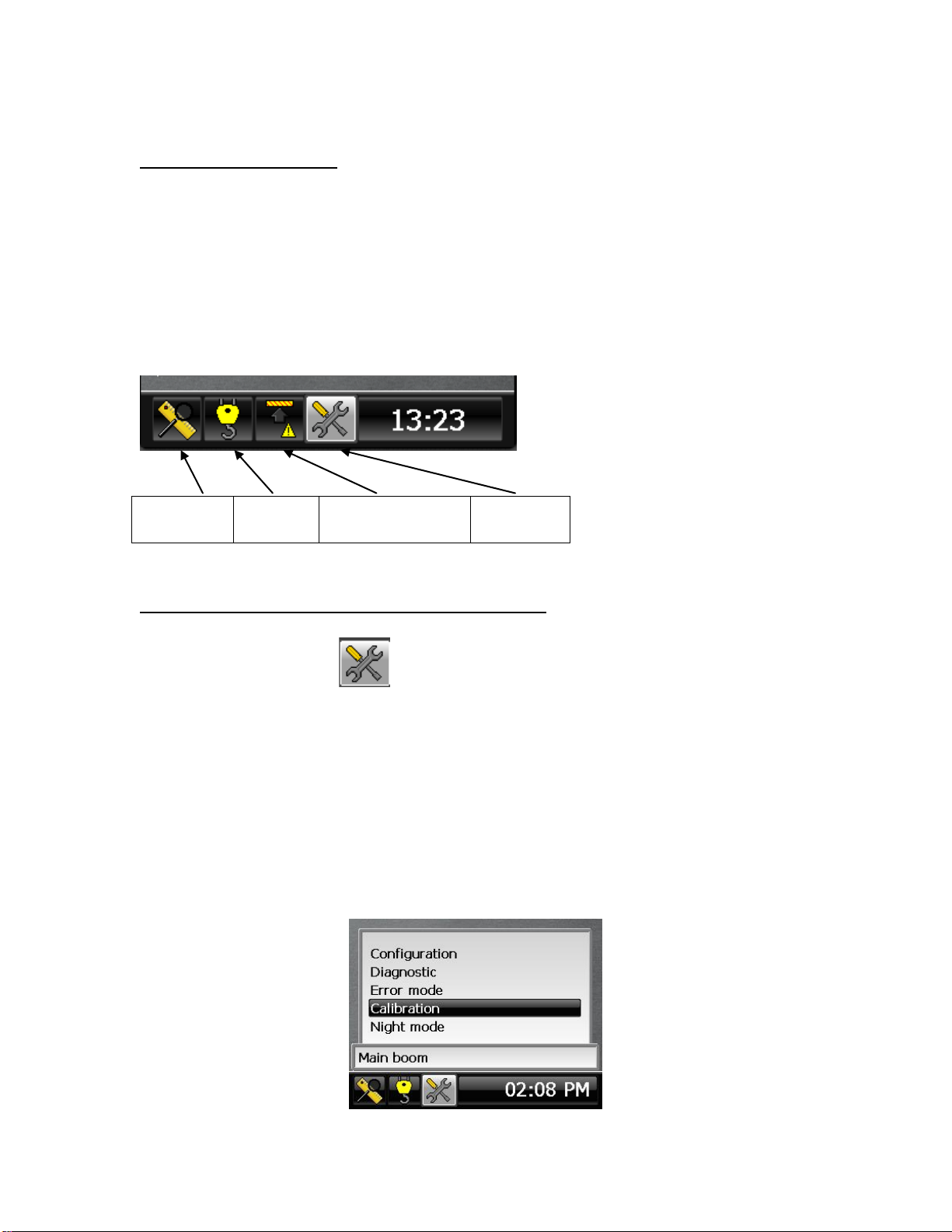
1- In the calibration menu, scroll down to the item "Load data:".
2- Press “”to enter this menu.
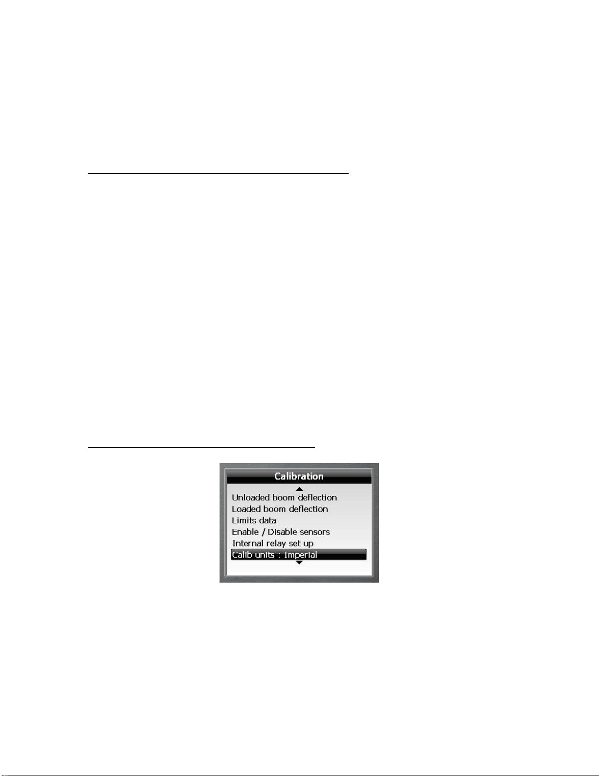
3- Scroll to select the item to edit from the list below.
4- Press “”to highlight the value to edit. Scroll up or down to change the value
then Press “”to confirm.
5- Any change made is permanently registered after confirmation.
6- Press Escape Key at any time to exit the menu when done.
Rope Limit Main: This is the maximum tension that the cable is rated for per fall or
part of line (rope SWL) for the main rope.
Rope Limit Aux : This is the maximum tension that the cable is rated for per fall or
part of line (rope SWL) for the auxiliary rope.
Max parts of line: This is the maximum number of parts of line that can be rigged on
the crane and applies to all hoists.
Load Approach (%): Is the %SWL approach limit. If the %SWL is greater than this
value, an intermittent audible alarm will be activated and the yellow display LED will
blink. The external yellow lamp output will be ON.
Note: %SWL = (Load / Capacity) x 100.
Overload (%): Is the %SWL motion cut limit. If the %SWL is greater than this value, a
continuous audible alarm will be activated and the red display LED will be ON. The
external red lamp and audible alarm output will be ON. The motion cut output will
be in the stop condition (cut active).
2.5 Step #5: “Limits data” Entry
This menu contains the approach warning gaps for all the limits that can be set by the
operator in normal mode.