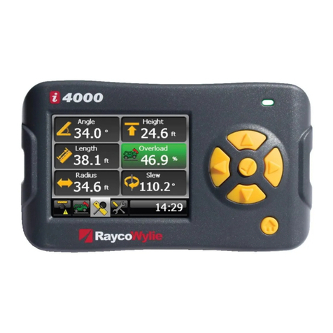
RaycoWylie i4500 Use and care manual

55M4500CCE00 REV A
Calibration Instructions
i4500 Rated Capacity Limiter/Indicator
for
telescopic cranes, pressure sensing
Crane safety instrumentation

55M4500CCE00 REV A

55M4500CCE00 REV A
The purpose of this manual is to provide the calibration technician with the procedures
essential for the promotion of proper machine operation for its intended purpose. The
importance of proper usage cannot be overstressed.
The calibration technician should have read, and be familiar with, the instruction
manual supplied with the system.
All information in this manual should be read and understood before any attempt is
made to calibrate the machine.
Since the manufacturer has no direct control over machine application and operation,
conformance with good safety practice in this area is the responsibility of the user and
his operating personnel.
All procedures herein are based on the use of the system under proper operating
conditions, with no deviations from the original design. Alteration and/or modification
of the equipment are strictly forbidden without written approval from RaycoWylie
Systems.
The i4500 RaycoWylie Systems Rated Capacity Indicator (RCI) is to be regarded only as
an aid to the operator. When the parameters are set correctly, the indicator will warn
the crane operator of an approaching overload condition that could cause damage to
equipment, property, and/or injury to the operator or site workers in the vicinity of the
crane and its load. Prior to the calibration being completed the system will not provide
correct warnings and it is essential that other means are used to establish safe use of
the machine.
This system must never be used, under any circumstances, as a substitute for the good
judgment of a crane operator when carrying out approved crane‐operating procedures.
Responsibility for the safe operation of the crane lies with the crane operator. The
indicator equipment will not necessarily prevent crane damage due to overloading and
related causes if not set properly.

55M4500CCE00 REV A
Before operating a crane equipped with a RaycoWylie system RCI, the operator must
carefully read the information in the i4500 operator manual and the crane manufacturer
operator’s manual. He must also be aware of all the federal, state and local safety
standard and regulations applicable to his job. Correct functioning of the system
depends upon routine daily inspection.
Any suspected faults or apparent damage should be immediately reported to the
responsible authority before using the crane.

55M4500CCE00 REV A
TABLE OF CONTENTS
1 INTRODUCTION....................................................................................................... 7
Personnel qualification and scope of this manual...................................................... 7
Using this manual ............................................................................................................ 7
2 CONFIGURATION .................................................................................................... 9
Step #1: Accessing the calibration menu.................................................................... 9
Step #2: “Enable/Disable i/o” Setting......................................................................... 10
Step #3: “Calibration units” setting............................................................................ 12
Step #4: “Calibration data” Entry................................................................................ 13
Step #5: “Dimensions” Data entry.............................................................................. 15
Step #6: “block capacities and block weights” setting ........................................... 18
Step #7: “system options” setting.............................................................................. 19
Step #8: “crane type”.................................................................................................... 20
Step #9: “bridging/bypass output” ............................................................................. 20
Step #10: “picture”........................................................................................................ 20
3 CALIBRATION........................................................................................................ 21
Step #11: “Zero sensor/Side of boom angle” angle sensor calibration................ 21
Step #12: “Zero sensor/Span sensor” length sensor calibration........................... 22
Step #13: “Zero pressure/Span pressure” sensor calibration................................24
Step #14: “select boom output sequence”................................................................26
Step #15: “No Load calibration”.................................................................................. 27
Step #16: “Loaded boom deflection” ......................................................................... 34
Step #17: Optional “Load adjustment” ...................................................................... 36
Step #18: Optional “Load offset” ................................................................................ 37
Step #19: Optional “Load correction” ........................................................................ 39
Step #20: “Friction compensation” ............................................................................ 43
Step #21: “Transfer” Calibration backup...................................................................43
“Transfer” restoring calibration and load chart files ................................................ 45
“Memory” ........................................................................................................................ 46
4 OPTIONS................................................................................................................. 47
“Limits setting” parameters.......................................................................................... 47

55M4500CCE00 REV A
“special calibration” ...................................................................................................... 47
“Users ID” Setting user pass codes for the data logger .......................................... 47
“rotation data” ................................................................................................................ 48
5 AUTOMATIC LOGS................................................................................................ 50
“Fault log” ....................................................................................................................... 50
“Event recorder” ............................................................................................................ 50

55M4500CCE00 REV A
UP button. Press to move up the screen when in a menu or to
increase the value of a highlighted number.
DOWN button. Press to move down the screen when in a menu or
to decrease the value of a highlighted number.
ESCAPE button. Press to exit a menu or to escape an option
without saving.
SELECT button. Press to enter a selection when in a menu or to
accept a changed value. Note that most changed values must also
be saved to permanently store them.
1INTRODUCTION
This manual contains calibration information for the i4500 system. When performing
calibration of the i4500 system, always observe the safety rules and regulations
applicable in the country of operation to reduce the risk of personal injury or damage to
the equipment. Each safety instruction throughout this manual must be taken into
consideration when using the i4500 system. The information contained in this manual
will enable qualified personnel to properly operate and efficiently perform calibration.
Personnel qualification and scope of this manual
Installation of the i4500 system shall be performed by a qualified technician.
Furthermore, calibration of the i4500 system must be performed by a RaycoWylie
trained technician. The RaycoWylie technician will perform a complete and structured
verification of the whole system before beginning the system’s calibration.
Failure to calibrate the system properly can result in overloading of the crane risking
machine breakage or tipping that could result in serious injury or death. Always refer to
a RaycoWylie trained technician to calibrate your system.
Using this manual
This manual must be used in conjunction with the Instruction Manual, refer to the
instruction manual for description of the system operation, especially the section
“Operating Buttons Description”.
Screenshots used in this manual are taken from a 4.3” display and some screens may
vary on larger display versions; calibration procedures, descriptions and functions are
identical for all display versions. All numbers shown on sample screens are examples
only and must be substituted with real information from the machine.
Navigating screens and editing data:

55M4500CCE00 REV A
Additional buttons used in the calibration mode only, refer to relevant text for detailed
use:
SAVE button. Press to save all recent changes into memory.
DELETE button. Press to delete a stage of some calibrations.
CLEAR button. Press to clear the fault log or the event log.
CHANGE SIGN button. Press to set a variable to negative or back to
positive.

55M4500CCE00 REV A
2CONFIGURATION
To ensure a successful, first calibration follow each calibration step in sequence, do not
miss out any steps unless they are marked as optional.
Many calibration screens show reminder notes or hints on the bottom line, remember
to read these for guidance.
Step #1: Accessing the calibration menu
1‐ Press the Mode button.
2‐ Scroll to highlight “Calibration Mode” using “” or “”.
3‐ Press “” to enter this menu.
4‐ The system will request a 5 digit password. The first digit will be highlighted, use
“” or “” to select the first digit and press “” to confirm and move on to the
second digit. Repeat this for all 5 digits, after confirming the 5th digit the system
will enter the calibration menu provided the password is correct. If the
password is not correct the system will return to the normal working screen.
5‐ If a mistake is made while entering the password, press “” to return to the
previous digit.
Some systems are installed with dual level password access, this manual includes
information on all features accessible from the top level. Some features will not be
available when the lower level password is entered and will not appear in the calibration
menu. It will not normally be necessary to access these features after the initial
installation is completed.
The calibration menu will remain accessible until the system is powered off.

55M4500CCE00 REV A
Step #2: “Enable/Disable i/o” Setting
Note: these settings reflect the configuration of your system and will generally be
made during factory testing prior to delivery and should not need changing.
1‐ In the calibration menu, scroll up or down to the menu "Enable/Disable i/o".
2‐ Press “” to enter this menu.
3‐ Scroll to select the I/O option to edit.
4‐ Press “” to highlight the value to edit. Scroll up or down to change to value
then Press “” to confirm.
5‐ Any change made must be permanently registered by pressing the “save”
button.
6‐ Press “” at any time to abandon any changes not saved or to exit the menu
when done.
As a guide, the minimum requirements for a basic system are:
Angle 1 ON
Length 1 ON
Load 1 ON
Load 2 ON
Relay board 1 ON
All remaining items in the list are optional and set to OFF if not used.
Refer to the wiring diagram supplied with your system to determine which I/O should be
enabled, this will be indicated by a table or a notation adjacent to each component. See
example below: (Ref Load 1 and Load 2) means that these two I/O items need to be ON.

55M4500CCE00 REV A
For the Generic and GPio items there
are various configuration options
available once enabled, refer to the
system wiring drawing for details of
which selection to set.

55M4500CCE00 REV A
GPio HDIN’s configuration
If GPio HDIN/HDOUT is set to ON in any of the above screens then an extra menu option
will appear in the main calibration menu to configure the use of the HDIN/HDOUT
connections.
Scroll to “GPio Hdins configuration” and press “” to enter, the screen will show
options to set each GPio that has HDIN/HDOUT set to ON:
Select the pair of inputs required, press “” to highlight the option currently set, use
“” or “” to scroll through the available options and then press “save” when the
required option is displayed. Refer to the wiring drawing supplied for the necessary
settings for your system.
Warning: these settings must match the relevant wiring drawing for proper operation
of the i4500 system.
Step #3: “Calibration units” setting
1‐ In the calibration menu, scroll up or down to the item "Calibration units:".
2‐ Press “” to toggle between metric and imperial.
imperial: use x1000lbs and feet.
metric: use metric tons and metres (1 metric ton = 1000 kg).

55M4500CCE00 REV A
Step #4: “Calibration data” Entry
Some or all of this information may be pre‐loaded prior to delivery but all entries should
be verified and edited as required before proceeding. Length units in use will be feet or
metres depending on the setting made for ‘calibration units’ in step #3, a reminder is
shown on the bottom line of this display. Remember to save any changes made. Please
advise Rayco Wylie of any changes required in this section.
1‐ In the calibration menu, scroll down to the item "Calibration data:".
2‐ Press “” to enter this menu.
3‐ Scroll to select the item to edit from the list below.
4‐ Press “” to highlight the value to edit. Scroll up or down to change the value
then Press “” to confirm.
5‐ Any change made must be permanently registered by pressing the “save”
button.
6‐ Press “” at any time to abandon any changes not saved or to exit the menu
when done.
Rope limit Main: This is the maximum tension that the cable is rated for per fall or
part of line (rope SWL) for the main rope.
Rope limit Aux: This is the maximum tension that the cable is rated for per fall or
part of line (rope SWL) for the auxiliary rope.
Max parts of line: This is the maximum number of parts of line that can be rigged on
the crane and applies to all hoists.
Percent per part: This value allows a reduction in the SWL of the hoist rope when
reeved to more than 1 part, the factor is applied to both main and auxiliary hoists.
For example: entering a value of 1.0 in this field will mean that the maximum load on
1 part will be the rope limit described above, the maximum load on 2 parts will be
two times the rope limit less 1.0%, the maximum load on 3 parts will be three times
the rope limit less 2%, the maximum load on 4 parts will be four times the rope limit
less 3% etc. Note that this value will be monitored simultaneously with the relevant
load table and the hook capacity, the lowest of these figures will be used as the
current SWL for alarm purposes.
Alarm 1: Is the %SWL approach limit. If the %SWL is greater than Alarm 1, an
intermittent audible alarm will be activated and the yellow display LED will blink. The
external yellow lamp output will be ON.
Note: %SWL = (Load / Capacity) x 100.

55M4500CCE00 REV A
Alarm 2: Is the %SWL overload limit. If the %SWL is greater than Alarm 2, a
continuous audible alarm will be activated and the red display LED will be ON. The
external red lamp and audible alarm output will be ON.
Alarm 3: Is the %SWL motion cut limit. If the %SWL is greater than Alarm 3, a
continuous audible alarm will be activated and the red display LED will be ON. The
external red lamp and audible alarm output will be ON. The motion cut output will
be in the stop condtion (cut active).
Gap for Multi‐Reel: This value is only valid if more than one boom length sensor
(extension reel) is fitted and represents the tolerance allowed for the position of the
non‐telescoping section(s) during the no load calibration procedure. If the fixed
boom sections are moved out of tolerance the calibration process will be suspended
until the situation is corrected.
Outside duty radius: This variable represents a transition distance between the
maximum radius rating and zero capacity, the SWL will decay evenly from the last
point on the chart to zero over the distance set by this variable and applies to all
charts.
Note: This option is valid only if the chart interpolation (in the system options menu)
is set to "ON".
Outside duty angle: This variable works in the same way as ‘outside duty radius’ but
is used for charts where the SWL is determined by boom angle and not radius.
Outside duty length: This variable represents an upper tolerance on the automatic
selection of the relevant load capacity chart for the actual boom length measured by
the system length sensor.
Inside duty length: This variable represents a lower tolerance on the automatic
selection of the relevant load capacity chart for the actual boom length measured by
the system length sensor.
Number of hoists: Set to the number of hoists (winches, or hooks) fitted to the crane,
1 for main hoist only or 2 for main and auxiliary hoists.
Duty change >20% SWL: If set to ON this option allows duty and parts settings to be
changed while a load is suspended, if set to OFF these changes will not be permitted
unless the load is less than 20% of the SWL.
Warning: This option must be set to OFF for European operation.
Sensitivity coefficient (5‐50%): The % value will determine how much variation is
required in order for the load variation to be outside the range of the filter, this
should be left at the default value of 35. The filter will only be functional in the
normal operating mode.
Low frequency Coefficient (10‐75): Adjusts the number of samples the filter will use,
this should be left at default value of 35. The filter will only be functional in the
normal operating mode.

55M4500CCE00 REV A
Step #5: “Dimensions” Data entry
This menu contains crane dimensions that are necessary for the calculation of the load
on the hook, based on the hydraulic cylinder pressure. This data refers to the winch and
boom hoist cylinder geometry at the superstructure and some main boom dimensions.
Some or all of this information may be pre‐loaded prior to delivery but all dimensions
should be verified and edited as required before proceeding. Units in use will be feet or
metres depending on the setting made for ‘calibration units’ in step #3, a reminder is
shown on the bottom line of this display. Remember to save any changes made.
Please advise Rayco Wylie of any changes required in this section.
Dimensions relating to boom tip attachments are stored in the chart file and are not
editable in this menu, *see note 2 (page 17).
CL1 (full retract): length of the main boom when fully retracted.
CL2 (full extend with extension): length of the boom with all sections fully extended
including any manual or power pinned extension if fitted.
CL2MR (full extend w/o extension): length of the boom fully extended but with any
manual or power pinned extension retracted. Note: For full power booms without a
manual section CL2 and CL2MR are the same value.
CL3 (p2blh) –horizontal distance between the boom foot pin and lift cylinder base
pin.
CL4 (p2blv) –vertical distance between the boom foot pin and lift cylinder base pin.
CL7 (p2buh) –distance between the boom foot pin and lift cylinder top pin parallel to
boom telescoping centerline.
CL8 (p2cb) –vertical distance between the boom foot pin and the boom centerline
with the boom horizontal. Instead of using the boom centerline as a reference, It is
common to use the boom foot pin, in this case CL8 = 0 but ensure that CL9, CL10 and
CL11 all use the same reference.
CL9 (ra2cb) –vertical distance between the lift cylinder top pin and the boom
centerline (or boom foot pin, see CL8) with the boom horizontal. If the boom
centerline is higher than the lift cylinder top pin, then the distance is positive,
otherwise it is negative.
CL10 ‐ vertical distance between the lower boom tip sheave pin (hook suspension
sheave) and the boom centerline (or boom foot pin, see CL8) with the boom
horizontal.
CL11 ‐ vertical distance between the upper boom tip sheave pin and the boom
centerline (or boom foot pin, see CL8) with the boom horizontal.
CR1 ‐ lower boom tip sheave pitch radius (hook suspension sheave).
CF (slew offset) –horizontal distance between the boom foot pin and the centerline
of rotation of the machine. If the boom foot pin is behind the centerline of rotation
then the distance is negative, otherwise it is positive.
CH1 (height rubber) –vertical distance between the boom foot pin and the ground
when on tires.

55M4500CCE00 REV A
CH2 (height outrigger) –vertical distance between the boom pivot pin and the
ground when on outriggers.
NR (number of rams) –number of boom lift cylinders, normally 1 or 2.
RD (rod diameter) –rod diameter of the lift cylinder.
BD (bore diameter) –bore diameter of the lift cylinder.
CR2M (m.h. radius) –radius of the main hoist drum from the center to the middle of
the hoist line layers.
CL5M (p2mhh) –horizontal distance between the center of main hoist drum and the
boom foot pin. If the drum is mounted on the boom, this dimension is zero.
CL6M (p2mhv) –vertical distance between the center of main hoist drum and boom
foot pin. If the drum is mounted on the boom, this dimension is zero.
CR22M –radius of the boom base mounted main hoist guide sheave, *see note 1.
CL28M –vertical distance between the boom base mounted main hoist guide sheave
and the boom foot pin measured when the boom is horizontal. *see note 1.
CL29M –horizontal distance between the boom base mounted, main hoist guide
sheave and the boom foot pin measured when the boom is horizontal. *see note 1.
CR2A (a.h. radius) –radius of the auxiliary hoist drum from the center to the middle
of the hoist line layers.
CL5A (p2ahh) –horizontal distance between the center of the auxiliary hoist drum
and the boom pivot pin. If the drum is mounted on the boom, this dimension is zero.
CL6A (p2ahv) –vertical distance between center of auxiliary hoist drum and boom
pivot pin. If the drum is mounted on the boom, this dimension is zero.
CR22A –radius of the boom base mounted, auxiliary hoist guide sheave,*see note 1.
CL28A –vertical distance between the boom base mounted, auxiliary hoist guide
sheave and the boom foot pin measured when the boom is horizontal. *see note 1.
CL29A –the horizontal distance between the boom base mounted, auxiliary hoist
guide sheave and the boom foot pin measured when the boom is horizontal. *see
note 1.
*Note 1: This option is rare and these values are generally set to zero. If a guide
sheave is fitted but mounted on the superstructure (not the boom) then the sheave is
treated as though it is the winch drum (see sketches).

55M4500CCE00 REV A
*Note 2: The chart file that contains all the relevant load charts and duty information
for the machine also contains dimensions, weights and center of gravity for all the
boom top attachments (fly jibs etc.). In some cases some of this data may not have
been available during the system configuration at the factory. In these cases it will be
necessary to obtain the information by surveying the hardware on site, the attending
Rayco Wylie technician will be equipped to update the load chart file with this data.
In the event of a Rayco Wylie technician not attending please refer to the dimension
sheet and contact Rayco Wylie Systems technical service and provide them with the
missing dimensions and weights. The load chart file will be updated with the verified
information and returned via email. Before calling please take note of the technical
file reference (TF‐xxxxx) and serial number located on the serial number label of the
display, alternatively, go to the diagnostics screen, select ‘system’ and note the full
name of the load chart file given there. This will enable our Technical Service
representative to efficiently access all the information about the system.
Note sign convention: All dimensions shown positive except cf, the centreline of
slew is generally in front of the boom pivot pin in which case cf is negative. If
any dimension falls the opposite side of it’s datum line shown in the diagram then
it’s sign will change eg if the top of the boom lift cylinder is above the centreline
of the boom then cl9 will be negative etc.

55M4500CCE00 REV A
Alternative location of
hoist drums using guide
sheaves on boom. For this
situation dimensions cl6a
and cl6m are negative.
Step #6: “block capacities and block weights” setting
This menu contains the capacities and weights of all the available hooks for the crane,
the hook(s) in use must be entered here for subsequent selection in the configuration
setting of the system. The capacity of each hook will be used by the i4500 system to
determine whether the current SWL for the configuration and position of the machine is
limited by the load curve, the parts of line or the hook capacity.
After selecting “block capacities and block weights” from the main calibration menu the
screen will show:
Set the capacity and weight of each hook block in turn using the calibration units set
earlier (noted at the bottom of this screen). Remember to press “save” once all the
data is entered. Numbers shown are for illustration purposes only and must be set to
show real data from the machine.

55M4500CCE00 REV A
Step #7: “system options” setting
The system options menu allows various features to be turned on and off and may vary
depending on the version of software installed in the i4500 system. These settings will
normally be pre‐set before delivery and will not require changing.
Navigate through the calibration menu using “” or “” to highlight “system options”
and press “” to enter.
Chart interpolation. Determines whether or not the i4500 system interpolates the
crane capacity charts with respect to radius/angle or whether it steps from one capacity
to the next. If chart interpolation is ON, the system will display a smooth transition
between rated points. If it is OFF, then once the radius/angle exceeds a listed value on
the chart the capacity will drop to the next rated capacity, this is known as a stepped
chart. Refer to the crane manufacturer’s load chart to determine if the charts should be
interpolated or stepped.
Datalogger. Allows the datalogger, if fitted, to be switched ON or OFF.
Crane ID. This is only used if a datalogger is installed and is a unique identifier for the
crane. It is used in conjunction with the Rayco Wylie data logger software for PC to
manage ‘whole life’ data for the machine and acts as an identifier for files once
downloaded and removed from the machine.
Password protection. This is only used if a datalogger is installed and, when set to ON,
will set the system to ask for a pass code number to be entered each time the system is
switched on. See also “user id” settings (page 47).
“Limit saved” message. Optional feature, if enabled then setting this to ON will display
a message on start up indicating a limit is saved if a limit has previously been set.
Limit access with HDIN. When set to ON, Limits menu is accessed via an external input
rather than the normal menu button. Refer to the wiring diagram for details if relevant.

55M4500CCE00 REV A
External setup button. Optional feature, if enabled then setting this to ON will allow
the setup bypass feature to be available via an external digital input.
Return time from limits. Not enabled unless the range limiting feature is fitted. This
value represents the time allowed between setting a range limit and the limit becoming
active to allow the machine to be moved back into the permitted working zone.
Dyno version. Must be set to OFF for this pressure sensing version of the i4500.
Step #8: “crane type”
This item is an option depending on the version of the software installed. When
available it allows the selection of one or more crane models within a single
manufacturer’s range to allow for differences in required features. It must be set to
precisely match the crane model to which the i4500 system is fitted.
Step #9: “bridging/bypass output”
This item is an option depending on the version of the software installed. When
available it allows the parameters to be set for the PWM output used to reduce the
machine speed during bridging or bypass functions.
Step #10: “picture”
This setting allows the graphic of the crane shown in the normal working window to be
set to a version that looks similar to the machine to which the system is fitted. It can be
set to any of the available choices at any time without changing the performance of the
system.
Other manuals for i4500
3
Table of contents
Other RaycoWylie Measuring Instrument manuals