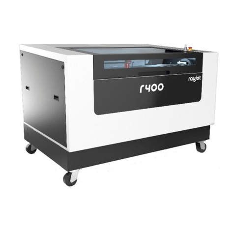
Rayjet 8015 User manual

SERVICE MANUAL
8015 Rayjet
07/09/2010 Trotec Produktions- und Vertriebs GmbH_Linzer Strasse 156, A-4600 Wels, Austria, Technical Support 1 / 53

TROTEC PRODUKTIONS
UND VERTRIEBS GmbH
Linzer Strasse 156
A – 4600 Wels
AUSTRIA
Ph.: ++43/7242/239-0
Fax: ++43/7242/239-7380
E-Mail: [email protected]
www.troteclaser.com
This publication and it´s contents are proprietary to Trotec Wels and are intended solely for the
contractual use of Trotec customers.
This publication and it´s contents may not be reproduced or distributed for any other purpose
without the written permission of Trotec Wels.
Notice
Trotec Wels does not assume any liability arising out of the application or use of any products,
curcuits or software described herein. Neither does it convey a license under it´s patent rights nor
the patent rights of others. Trotec Wels further reserves the right to make any changes in any
products described herein without notice. This document is subject to change without notice.
CAUTION
Use of controls or adjustments or performance of procedures other than those
specified herein may result in hazardous laser radiation exposure.

Service Manual Rayjet
Table of contents
1MAIN COMPONENTS ......................................................................................... 5
2SAFETY INFORMATION..................................................................................... 6
2.1 General .......................................................................................................................................6
2.2 Laser Safety ...............................................................................................................................8
2.2.1 Safety Interlock System....................................................................................................... 9
2.3 Dangers of Electricity..............................................................................................................10
2.4 Emission indication and safety labeling ...............................................................................11
2.4.1 Light Emitting Diodes......................................................................................................... 11
2.4.2 Audible Warning ................................................................................................................ 11
2.4.3 Safety Labels..................................................................................................................... 11
3BEAM ALIGNMENT .......................................................................................... 12
3.1 Laser beam alignment.............................................................................................................12
3.2 Laser pointer adjustment........................................................................................................16
4REPLACING THE LASER TUBE ...................................................................... 17
4.1 Measuring the laser power:....................................................................................................18
4.2 Replacement of the lasertube ................................................................................................20
5ADJUSTING THE MINI-MANAGER OPTIONS................................................. 21
5.1 Tab „Options“..........................................................................................................................21
5.2 Tab „Service“...........................................................................................................................22
5.3 Tab „Information“ – Firmware Update ..................................................................................23
6HARDWARE...................................................................................................... 26
6.1 X- and Y-axis ............................................................................................................................26
6.1.1 Adjusting the Offset (0/0 position) ..................................................................................... 26
6.1.2 Exchange of the reels on x-axis ........................................................................................ 27
6.1.3 Exchange of the belt on x-axis .......................................................................................... 27
6.1.4 Special instructions for X-belt tensioning .......................................................................... 27
6.1.5 Exchange of x-motor.......................................................................................................... 28
6.1.6 Exchange of x-axis ............................................................................................................ 28
6.1.7 Exchange of y-motor.......................................................................................................... 28
6.2 The electric system .................................................................................................................30
6.2.1 I/O board with CPU board and motor prints...................................................................... 31
6.2.2 CPU board......................................................................................................................... 31
6.2.3 Motor prints........................................................................................................................ 32
6.2.4 Power supplies ..................................................................................................................32
6.2.5 Lasertube........................................................................................................................... 33
6.2.6 Motors................................................................................................................................ 33
6.2.7 Keypad............................................................................................................................... 34
6.3 Wiring diagrams.......................................................................................................................35
6.3.1 12W air-cooled................................................................................................................... 35
6.3.2 30W air-cooled................................................................................................................... 36
7ERROR CODES................................................................................................. 37
7.1 Software feedback...................................................................................................................37
07/09/2010 Trotec Produktions- und Vertriebs GmbH_Linzer Strasse 156, A-4600 Wels, Austria, Technical Support 3 / 53

7.2 Hardware feedback..................................................................................................................39
8RECOMMENDED SERVICE INTERVALS......................................................... 40
9RECOMMENDED TOOLS................................................................................. 41
10 RECOMMENDED SPARE PARTS RAYJET - STARTER KIT.......................... 42
11 FAQ’S................................................................................................................ 43
11.1 Problems you can see in the engraving or cutting result...................................................43
11.1.1 Trotec test routine.............................................................................................................. 43
11.1.2 Customer experience ........................................................................................................ 44
11.2 Machine malfunctions.............................................................................................................45
11.2.1 No error code is created.................................................................................................... 45
11.2.2 Error code is created ......................................................................................................... 46
11.3 Problems with the Software................................................................................................... 47
11.4 Laser Quick Check ..................................................................................................................50
11.5 Samples....................................................................................................................................51

Service Manual Rayjet
Main components
General
07/09/2010 Trotec Produktions- und Vertriebs GmbH_Linzer Strasse 156, A-4600 Wels, Austria, Technical Support 5 / 53
1 Main components
Top view
Back view
1 keypad
2 top lid
3 maintenance panel
4 service access panel
5 lasertube
6 on/off switch / power socket
7 power supply units
8 electronics
9 connection for PC and exhaust unit
10 connection for exhaust hose
11 product ID lable
1
2
3 4
10
9
5
6
7
8
11

2 Safety information
Please read this chapter before operating or servicing a Rayjet laser system!
2.1 General
The Rayjet is an apparatus with a high level of security. To guarantee a safe operation it is
necessary to know potential dangers and avoid risks. The dangers can be classified in three
categories:
ÒDangers caused by the laser beam
ÒDangers caused by electricity
Òmechanical dangers
General Safety Instructions
When working with the laser engraver please take note of the following safety instructions:
1. Operation and service of the Rayjet may only be performed by trained personnel.
2. Direct exposure of skin or eyes to laser radiation may cause severe injuries. The correct
operation and service according to the manual can prevent hazards. Operators may
perform procedures required inside the housing only through the interlocked door. They
must never attempt to defeat the door interlocks nor remove non interlocked portions of
the housing.
3. The laser beam can ignite flammable materials. Therefore a fire extinguisher should
always be nearby. Do not store flammable materials near or inside the laser engraver.
Working with the laser or setting the system to service mode without supervision
is not permitted.
4. Many materials, especially non-anodized aluminium, copper, silver and gold, cannot be
engraved with the laser engraver due to the very low absorption of laser radiation. This
means that most of the energy of the laser beam is reflected. Therefore those materials
must not be present in the laser beam path as otherwise a reflected laser beam could
destroy the cover of the laser unit.
5. Beam adjustment may only be done by trained personnel. Otherwise there could be
uncontrolled emission of laser radiation. There are only limited possibilities to adjust the
mirrors due to a mechanic restriction. These restrictions may only be altered by
authorized personnel.
6. Before starting to work check whether the engraving of the material can cause harmful
fumes and whether the filters of your exhaust system are suitable for these fumes. It is
emphasized that it is the user’s responsibility to obey the national and regional threshold
values for dusts, fumes and gases. (The maximum concentration of harmful substances
MUST NOT be exceeded). Never use the laser engraver without an exhaust unit with
appropriate filters for the treated material, as cutting or engraving certain materials can
produce vapours. Materials causing toxic or carcinogenic smokes or fumes must not be
treated without an exhaust unit with appropriate filters. Furthermore it is the user’s

Service Manual Rayjet
General
Safety information
07/09/2010 Trotec Produktions- und Vertriebs GmbH_Linzer Strasse 156, A-4600 Wels, Austria, Technical Support 7 / 53
responsibility to ensure the safe removal and disposal of the smokes and particles from
the laser machine according to the national and regional threshold values.
In the US reference should be made to Section 7.3 in the ANSI Z136.1-1993 Standard
for the safe use of lasers, to the exposure criteria in CFR 1910 Subpart Z from the US
government, and to the Threshold Limit Values (TLVs) published by the American
Conference of Governmental Industrial Hygienists (ACGIH).
7. Please refer to the manual of your exhaust system regarding the change intervals of the
filters. We recommend to make a note of the last change of filters on an adhesive label.
8. PVC (Polyvinylchloride) MUST NOT be processed with the laser engraver.
If you have any questions please contact your supplier or Trotec.

2.2 Laser Safety
The safety of a laser machine is defined by one of five safety classes.
The Rayjet without laser pointer would be safety class 2 in the EU safety class 2.
With an installed laser pointer it would be laser class 2M. Therefore it presents no hazard to
personnel when properly used during normal operation or routine maintenance. In the US all
machines are classified as classII laser products. This status is guaranteed by the safety housing
and safety devices that are installed in the product.
Please be aware that improper operation of the laser machine nullifies this safety class and allows
under certain circumstances the emission of radiation which can be potentially dangerous.
CO2- Laser
This laser engraving system may contain a carbon dioxide (CO2)-laser class IV (4) product, which
emits an intensive and invisible radiation. Without safety devices the direct radiation and also
diffuse reflected radiation is dangerous.
Please be aware:
The Laser Radiation of a CO2Laser is invisible!
Risks of Laser Radiation:
If the built in safety mechanisms are defeated and the laser is operated with the housing open,
there is a risk of setting clothing or other flammable materials on fire. Laser energy at a power of
up to 45W at a wavelength of 10,6 μm for CO2- Laser could be present inside the housing.
Therefore operators can perform procedures required inside the housing only when the interlocked
door has been opened. (A normal user must never defeat the door interlocks or remove portions of
the protective housing, except the machine is not powered).
Therefore you must under no circumstances neither alter the laser tube unit nor dismantle it nor set
a system to work which has been altered or dismantled!

Service Manual Rayjet
Laser Safety
Safety information
07/09/2010 Trotec Produktions- und Vertriebs GmbH_Linzer Strasse 156, A-4600 Wels, Austria, Technical Support 9 / 53
2.2.1 Safety Interlock System
Your Rayjet is equipped with an integrated safety interlock system which cuts off the power of the
laser tube immediately as soon as one of the interlocked doors/panels is opened.
CAUTION
Do not attempt to alter the interlock system as that could result in hazardous radiation
exposure.
CAUTION
Technicians who are performing service procedures must be trained in laser safety,
and if they are defeating interlocks, they must wear laser protective eyewear designed
for the 10,6μm CO2laser energy.
The top door and the maintenance panel on the right side, are interlocked. If the interlocks are
defeated access to laser class IV radiation is possible through any of these doors.
CAUTION
When a non interlocked cover is opened (and the machine is powered) access to
class IV laser radiation is possible.
These covers are labeled with „DANGER: INVISIBLE LASER RADIATION WHEN
OPEN. AVOID EYE OR SKIN EXPOSURE TO DIRECT OR SCATTERED
RADIATION“
Top lid interlocks
Maintenance
panel
interlocks

2.3 Dangers of Electricity
When you open the covers of the engraving system there is the danger to get in contact with parts
under high voltage. Therefore it is absolutely necessary that service and repair work is only done
while the power supply is unplugged. In any case all safety laws and standards in connection with
electricity must be obeyed.
IMPORTANT REMARK:
Usually you do not need to get in touch with the electrical and electronic components. In
case you do that when servicing or repairing the laser engraver, please be sure that you
first plug off the power supply.

Service Manual Rayjet
Emission indication and safety labeling
Safety information
07/09/2010 Trotec Produktions- und Vertriebs GmbH_Linzer Strasse 156, A-4600 Wels, Austria, Technical Support 11 / 53
2.4 Emission indication and safety labeling
2.4.1 Light Emitting Diodes
There is a red LED (light emitting diode) on the left hand side of the keypad which is illuminating
when laser radiation is emitted.
During engraving, the LED flashes very fast and might be hardly seen by the eye. During cutting-
mode it is durable.
2.4.2 Audible Warning
When starting up the laser engraver without closing the cover there is an intermittent beep. This
indicates that the interlock system has not been checked yet. (You can run the machine only if all
interlock switches are closed). Close the cover of the laser engraver to cause the machine to
initialize.
On emitting a laser beam (which is called test pulse) by pressing the „Play/pause"- and "Stop"
button simultaneously there is a beep (as long as you keep the buttons pressed) to remind you of
the possible risks.
2.4.3 Safety Labels
The laser safety standards require that any removable panels that could permit access to laser
energy include laser safety labels. These labels are visible before and after opening a cover.
Labels with the name of the manufacturer, date of production, description of the product, model
number, serial number and safety labels are placed on the outside of the apparatus. All these
labels are mounted when producing the laser engraver. These labels must not be removed.
If the labels are lost or damaged please contact Trotec. Replacements will be sent to you. All
labels and their exact place is mentioned in the user manual.
The labeling meets the standards
)
21 CFR 1040 – Laser safety
and
)
IEC 60825-1(2007)

3 Beam alignment
3.1 Laser beam alignment
Attention: To do the laser pointer adjustment it is absolutely necessary to wear laser
protection glasses!
What you need
laser protection glasses (for CO2lasers) part number 69300
the toolbox enclosed to the engraver
beam alignment tools (BAT) for mirrors #2 & #3
CAUTION To make sure that there is no laser emission out of a controlled area
establish a limited access area by using non flamable beam blocking curtains,
temporary walls or other enclosures.
CAUTION The laser beam alignment may only be performed by service
technichians that have been trained by Trotec and are familiar with the hazards from
lasers
CAUTION
Never expose any part of your body to the beam as this could result in serious
injuries.
CAUTION
To do the alignment it is absolutely necessary to wear laser protection
glasses.
What you have to know
The number of the mirrors is counted from the outlet of the laser tube to the engraving head from
one to three.
The whole alignment is done while your machine is running. To make sure the system works at a
suitable power level change the test-pulse power in the Manager.
The laser beam is invisible. To find out its path, you use a BAT for CO2lasers. It is burned at the
spot, where it is hit by the laser beam and shows a mark.
The tolerable displacement (distance from burned dot to the centre) is one sixth of the diameter of
the mirror or hole where you check the position.

Service Manual Rayjet
Laser beam alignment
Beam alignment
07/09/2010 Trotec Produktions- und Vertriebs GmbH_Linzer Strasse 156, A-4600 Wels, Austria, Technical Support 13 / 53
Beam path of the Rayjet:
Illustration is with removed service and maintenance panel.
What you have to do
1. Put on your laser protection glasses.
2. Remove the three screws shown below on the right inside of the working area and disassemble
the panel.
Mirror 3
Mirror 2
Mirror 1

3. Remove mirror #2 on the right side of the x-axis.
4. Remove the cover of mirror #1 carefully
5. Put the BAT for mirror #1 & 2 on the holder of mirror #2.
6. Turn on the Rayjet.
7. Connect the Rayjet to the Manager and ensure that the testpulse the options of the Mini
manager is set to a low level (~10%) before doing the beam alignment. You find this menu
through right-click on the small red icon on the left side of the task bar.

Service Manual Rayjet
Laser beam alignment
Beam alignment
07/09/2010 Trotec Produktions- und Vertriebs GmbH_Linzer Strasse 156, A-4600 Wels, Austria, Technical Support 15 / 53
8. Bridge the interlock system by putting magnets on the interlocks.
9. Move the x-axis to the 0/0 position.
10.Press the “Start/Pause” and “Stop” buttons (see picture besides) simultan-
eously until you see a little mark on the BAT which is firstly getting grey
(burned) and then lightening up. This is only possible if all interlocks are
closed.
If you cannot see the mark at all, align mirror #1 until you can see it.
11.Move the x-axis with mirror #2 to the front side of the machine (400/0).
12.Again press the “Start/Pause” and “Stop” buttons simultaneously until you see
a little mark.
Adjust mirror #1 until this second mark is at the same position as the first mark (generated in
step 10).
13.Repeat the steps 9to 12 until the marks are in the same position. As soon as they are in the
same position, follow up with the next steps.
14.Put mirror #2 back on.
15.Put the BAT for mirror #3 on the beam entrance of mirror unit #3.
16.Move the engraving head to the 0/300 position.
17.Press the “Start/Pause” and “Stop” buttons simultaneously until you see a little mark on the
BAT again.
18.Move the engraving head to the 0/0 position, do a testpulse again and adjust mirror #2 until you
hit the mark created in step 17.
19.Repeat steps 16 to 18 until the marks are in the same position.
20.If the mark is not centered bring it to the center by adjusting one of the screws for the laser
tube fixing plate. In this way you can bring the laser beam up or down.
21.Check the alignment at all four corners of the working table again.
22.When the position of the mark is in the centre with maximum displacement (distance from
burned dot to the centre) which is one sixth of the diameter of the mirror or hole where you do
the adjustment, you may remove the BAT from mirror #3.
23.Seal the adjustment screws by putting some varnish to them.
24.Put the cover for mirror #1 back on.
25.Now your engraver is aligned properly.
26.Put the maintenance panel back to the Rayjet and close it.

3.2 Laser pointer adjustment
Attention: To do the laser pointer adjustment it is absolutely necessary to wear laser
protection glasses!
What you need:
laser protection glasses (for CO2lasers) part number 69300
the toolbox enclosed to your engraver
beam alignment tool (BAT) for mirror #3
What you have to know:
Connect the laser to the Manager and ensure that the testpulse setting within the Manager is set to
a low level (~10%) before doing the beam alignment.
The CO2 laser beam is invisible. To find out its path, you use the BAT for CO2lasers. It is burned at
the spot, where it is hit by the laser beam and shows a mark.
The tolerable displacement (distance from burned dot to the centre) is one sixth of the diameter of
the mirror or hole where you do the adjustment.
1.) After you´ve installed the laser pointer put the BAT on the mirror #3 on the x-axis.
2.) Move the engraving head to the lower left corner of the engraving table (0/300).
3.) Press the “Start/Pause” and “Stop” buttons simultaneously until you see a little mark on the
BAT. This is only possible if all interlocks are closed.
4.) Adjust the three small screws close to the laser pointer until the red dot hits exactly the burned
spot on the BAT.

Service Manual Rayjet
Replacing the laser tube
4 Replacing the laser tube
The laser tube is one of the main components of any laser engraver. The Rayjet uses Synrad
tubes for all systems.
To make the tube fire it must be
- Connected to the power supply
- Provided with a control signal of the data cable (BNC connector)
The control signal is a 5V TTL signal that comes from the main board.
All tubes have an integrated overtemperature protection. If the tube exceeds a certain temperature
it is switched off to prevent a damage of the gas/electronics.
The following reasons might make it necessary to replace the tube:
•Too low laser power
•Fluctuations of laser power (typically jumps from 100% to 50% engraving depth)
The frequency of these power fluctuations is low (e.g. every 5 minutes)
•Uncontrollable timing behaviour (high frequency effect).
This effect shows shifted start/end points of the pulses so that the image looks frayed
although the mechanics (of the motion system) and software adjustment are OK.
When you receive a new lasertube for the Rayjet, the tube is mounted on a plate and already
adjusted in a way, that it should not be necessary to adjust the beampath. If there are some
missalignments, do the alignment as described before in chapter 3.
Please consult the Rayjet Video DVD to find detailed instruction on how to exchange the laser
tube.
07/09/2010 Trotec Produktions- und Vertriebs GmbH_Linzer Strasse 156, A-4600 Wels, Austria, Technical Support 17 / 53

4.1 Measuring the laser power:
To measure the laser power you need:
1. laser protection glasses (for CO2lasers) part number 69300
2. Laser power meter
CAUTION To make sure that there is no laser emission out of a controlled area
establish a limited access area by using non flamable beam blocking curtains,
temporary walls or other enclosures.
CAUTION The laser power measurement may only be performed by service
technichians that have been trained by Trotec and are familiar with the hazards from
lasers
CAUTION
Never expose any part of your body to the beam as this could result in serious
injuries.
CAUTION
To do the laser power measurement it is absolutely necessary to wear
laser protection glasses.

Service Manual Rayjet
Replacing the laser tube
Measuring the laser power:
07/09/2010 Trotec Produktions- und Vertriebs GmbH_Linzer Strasse 156, A-4600 Wels, Austria, Technical Support 19 / 53
1. Open the mini manager and connect to the engraver.
2. Enter the Options via right-click on the small red rayjet icon on the left side of the task-bar.
Choose “Service” and set “Power test pulse” to 100%. Press Apply.
increasing the test pulse to full power
3. Put on your laser protection glasses.
4. Remove the cover of mirror #1.
5. Put the power meter with the black absorbing area between the aperture of the lasertube
and mirror #1.
6. Press the reset button on the power meter and fire the testpulse (press “Start/Pause” and
“Stop” buttons simultaneously)
7. After some seconds you will hear a beep sound from the power meter, which indicates that
the measurement has been finished.
8. Repeat the procedure at least three times. Take care that the power meter will not overheat
when doing this test.
The wattage difference between the tests should be less than 10% of the average laser power.
After this test, reset the “Power test pulse” to 10%.

4.2 Replacement of the lasertube
The concerned parts in replacement of lasertubes are placed on the backside of the machine.
cover of lasertube
cover of mirror #1
holding plate
fans
power supplies
Do the following steps to exchange the lasertube.
1. Switch off the Machine and unplug it from the electrical outlet.
2. Unplug the power connectors of the lasertube-ventilators and the lasertube.
3. Unplug the data-cable of the lasertube.
4. Remove the cover of mirror #1 and remove the mirror itself. Keep the mirror to replace it
again after mounting the new tube.
5. Loosen the five screws marked below and carefully remove the cover of the lasertube
together with the ventilators.
6. Loosen the three screws holding the holding plate of the lasertube (see picture below).
7. Lift and remove the lasertube together with the mounted holding unit of mirror #1.
8. Assemble the new tube in the reverse way.
9. After the replacement you´ve to check the beam alignment as described before.
10. Pack the old tube and ship it back to Trotec.
Table of contents
Other Rayjet Cutter manuals