RI-D340-IM-V02
1
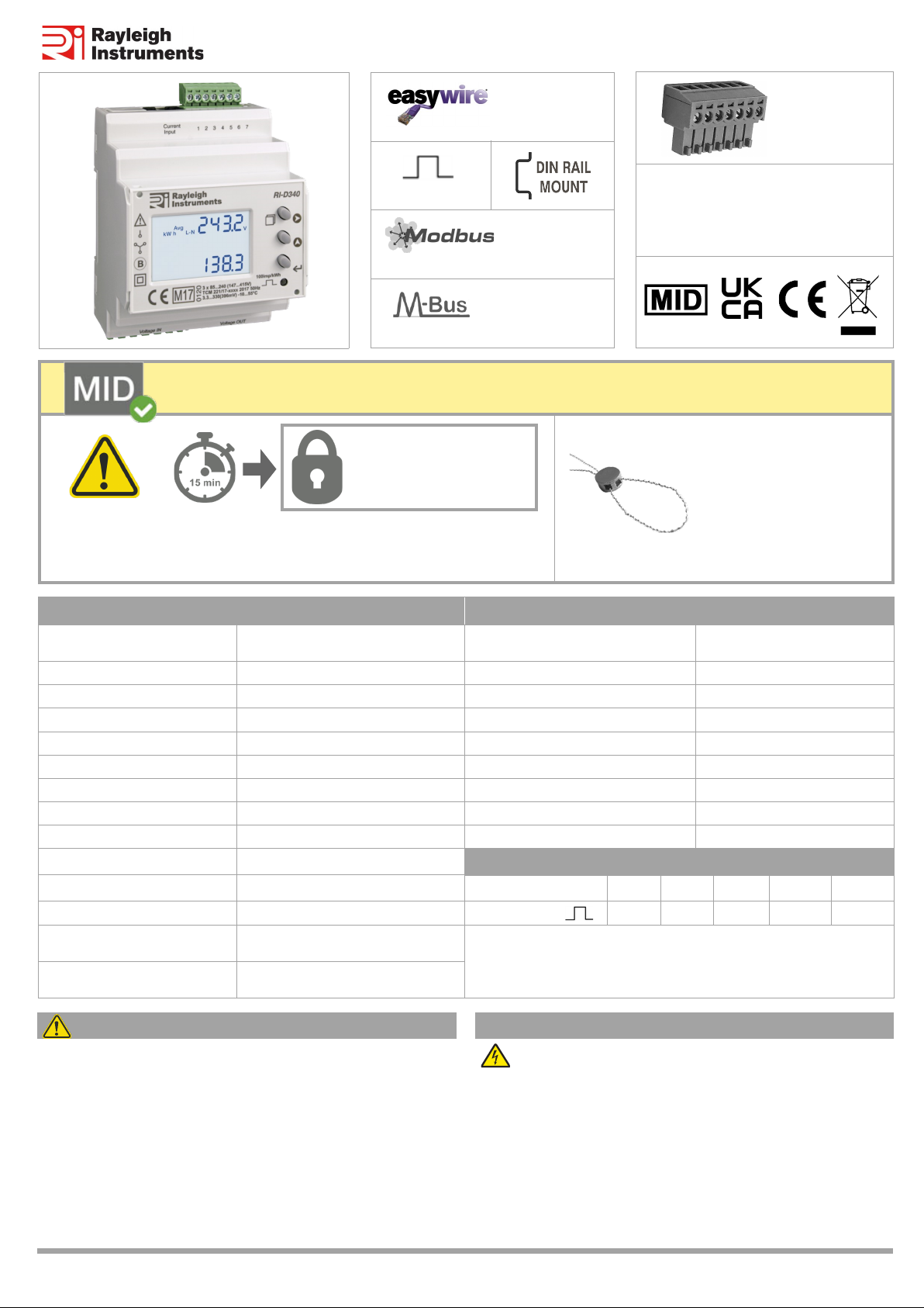
RI-D340 Instrucon Manual
X 1
Safety related noficaon, symbols and instrucons that appear in this
operang manual or on the equipment must be strictly followed to
ensure the safety of personnel as well as the instrument. If the
equipment is not used in a manner specified by the manufacturer it may
impair the protecon provided by the equipment
· Do not use the equipment if there are mechanical damage
· Do not exceed the stated maximum rangs of the device
· No repairs, maintenance or adjustments are possible
· Read the complete instrucon manual prior to installaon or
operang the unit
· The equipment in its installed state must not come into close
proximity to any heang sources, oils, steam, causc vapours or
other unwanted process by-products
· Do not use in hazardous or classified locaon where explosion or
other dangers can be triggered by the device
PRODUCT SAFETY INSTALLATION PRECAUTIONS
Risk of electric shock!
Only to be installed by a competent person
· To prevent the risk of electrocuon, always isolate and lock-off the
power supply to the equipment prior to undertaking any work
· Always confirm absence of electricity prior to starng work using
appropriate voltage detecon equipment
· Wiring shall be done strictly according to the terminal layout
· Confirm that all connecons are correct before energizing the
equipment
· Roung of cables shall be way from any internal EMI source
· Copper cable should be used
· All wiring to be in accordance with applicable local standards
Once Configuraon Mode is entered, ‘Configuraon Lock’ will acvate
aer 15 minutes or if meter is switched off. No further adjustment is
possible for the lockable sengs. Unlock only by returning to supplier.
All terminal covers provided
must be fied. All cable
connecons and terminal
covers of the meter and the
CT must be secured with
sealing hasp.
Installaon must comply with MID cerfied requirements
Configuraon Lock
>> see ‘Configuraon’
for Lockable Sengs
Specificaons Accuracy
Wiring Input 3Ø 4 wire (MID Approved)
1Ø 2 wire - P1, P2, P3 (All MID Approved) Voltage V L-N and V L-L ±0.5% of full scale
Rated Input Voltage 3x 85...240V AC (L-N), 147...415V AC (L-L) Current ±0.5% of full scale
Frequency 45...65Hz (MID approved @50Hz) Frequency for L-N > 20V, L-L > 35V ±0.1% of full scale
CT Primary 1...6,000A configurable Acve, Reacve and Apparent Power 1%
CT Secondary 0.01...1(1.2)A (Meter Input: 330mV) Power Factor ±0.01 of Unity
VT Primary 100...600V configurable Acve Energy EN50470-3: Cl.B
VT Secondary 100...500V AC (L-L) configurable Reacve Energy EN62053-23: Cl.2
Voltage Rated Burden < 8VA
Display Update Rate 1 sec all parameters Wh Resoluon and Default Pulse Weight
Operang / Storage Temperature -10…55°C / -20…75°C
Example
If CT Primary = 200A (CT rao = 200/1 = 200) & VT = 350/350V (VT Rao = 1)
Wh resoluon = 1kWh (200 x 1 = <1500) | Pulse O/P default = 1kWh/pulse
Humidity 0...85% non-condensing
Protecon Degree (IEC/EN60529) IP54 (front of Housing), IP20 (terminals)
Communicaon Modbus RTU over RS485
MBus (EN13757)
Auxiliary Supplied from any phase Apparent Energy Class 1
CT Rao x VT Rao <15 <150 <1500 <15000 >15000
Wh / kArh / VAh / 0.01k 0.1k 1k 0.01M 0.1M
EO&E: Document subject to change
1x 3Ø
1x 1Ø
3x 1Ø
RI-D340-G-C
RI-D340-G-MB
RTU
Pulse SO