Raymarine hsb2 Series User manual

USB2 to hsb2
Interface Box
User’s Guide
Document number: 81251-1
Date: November 2004

2 RayTech USB2 to hsb
2Interface Box
RayTech USB2 to hsb2Interface Box
The Raymarine USB2 to hsb2Interface Box connects your PC to an hsb2network, enabling
you to view RayTech data on all hsb2PLUS Series (Pathfinder) displays on the network. The
Interface Box provides a USB2 port for connecting to the PC and two internallyterminated and
separate hsb2ports,which the Interface Box links into one contiguous hsb2network.
The PC is not required for proper operation of Ports 1 and 2 on the hsb2network.
The USB2 to hsb2Interface Box works with USB 2.0 only. If yourPC does not have a
USB 2.0 port, you will need to install one using a PCI or PCMCIA USB 2.0 adapter.
The Interface Box does not work properly on a USB 1.x port.
IMPORTANT NOTE: Touse the USB2 to hsb2Interface Box you must ensure that
RayTech HSB2 configuration is set to USB2.0. This can bedone when you run
RayTech Navigator. Select FILE > SETUP > INSTRUMENTS > HSB2 CONFIG >
USB2.0 FOR HSB2 NETWORK CARD.
Connector Panel
The USB2 to hsb2Interface Box connector panel provides the following connections:
•POWER connects to the DC power supply via the supplied power cable.
•PORT 3 connects to the USB2 port in your computer via the supplied USB cable.
•PORT 2 connects to Pathfinder display unit(s) and DSM(s) on the second hsb2
network.
•PORT 1 connects to display(s) and DSM(s) on the first hsb2network.
Note:
PORT 1 and PORT 2 are attached to separatenetworks.The Interface Box links these
into one contiguous hsb
2
network. hsb
2
connection cables must be purchased separately.
Raymarine
Power
10-36Vdc
PORT 2PORT 3
RECON
STATUS
USB
PORT 1

RayTech USB2 to hsb2InterfaceBox3
TheUSB2tohsb2Interface Box connector panel provides the following indicators:
•STATUS is a green LED that lights when the Interface Box is operating properly.
•RECON is an amber LED that lights when there is an error situation.
•USB is a green LED that lights when the unit is properly connected to the PC.
•3is a green LED that lights when the PC is properly connected to the Interface
Box and the USB firmware is loaded.
•2is a green LED that blinks when the unit is powered on and then lights solid
when the unit is properly connected to the network and receiving data on Port
2.
•1is a green LED thatblinks when the unit is powered onand then lights solid
when the unit is properly connected to the network and receiving data on Port
1.
Hardware Installation
The Raymarine USB2 to hsb2InterfaceBox is designed to be mounted in a dry
location where it is:
•protected from physical damage and excessive vibration
•protected from exposure to rain, salt spray and direct sunlight
•well ventilated
Mounting
Toinstall the Interface Box:
1.Use the four mounting holes to secure the Interface Box in the desired location.
2. Attach the required cables.
DC Power Connection
The USB2 to hsb2InterfaceBox is intended for use on boat’sDC power systems rated
from 10 to 36 volts. A 5ft (1.5 m) power cable is supplied for connecting the boat’s
DC power to the unit. The power cable may be extended by up to 60 ft (20 m) using
a wire gauge of AWG 12 or greater.
DC power is connected at the POWER connector on theunit’sconnector panel. The
RED wire must be connected to the feed from the positive (+) batteryterminal and
the BLACK wire to the feed from thenegative (–) battery terminal. The other wires
in this cable are not used.
The Interface Box is reverse polarity protected and has a current draw of 400ma @
12VDCor 5 watts (max).

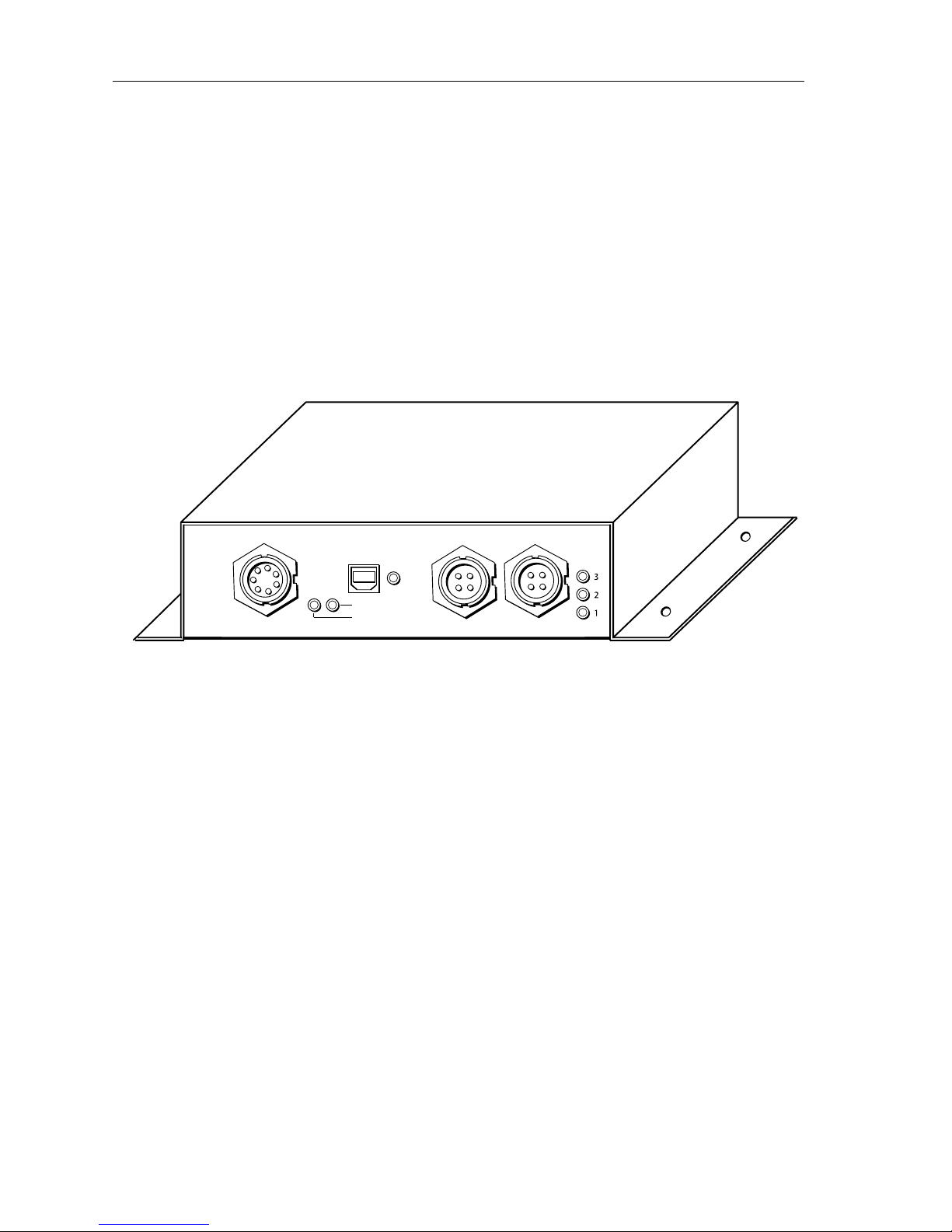
4RayTech USB2 to hsb2Interface Box
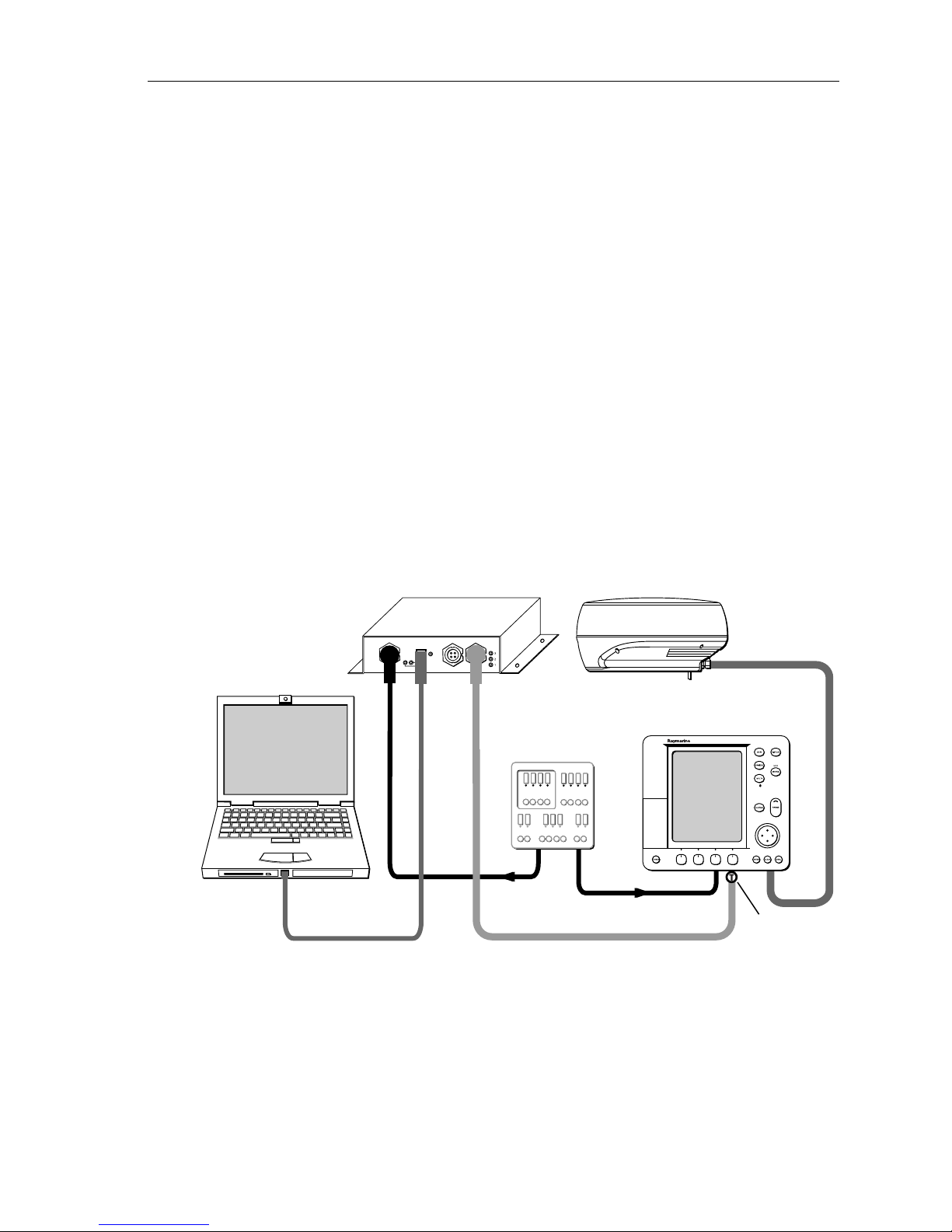
USB2 Connection
Connect the provided USB2 cable fromthe port marked USB on the Interface Box to
a USB2 connection on yourPC.
hsb2Connection
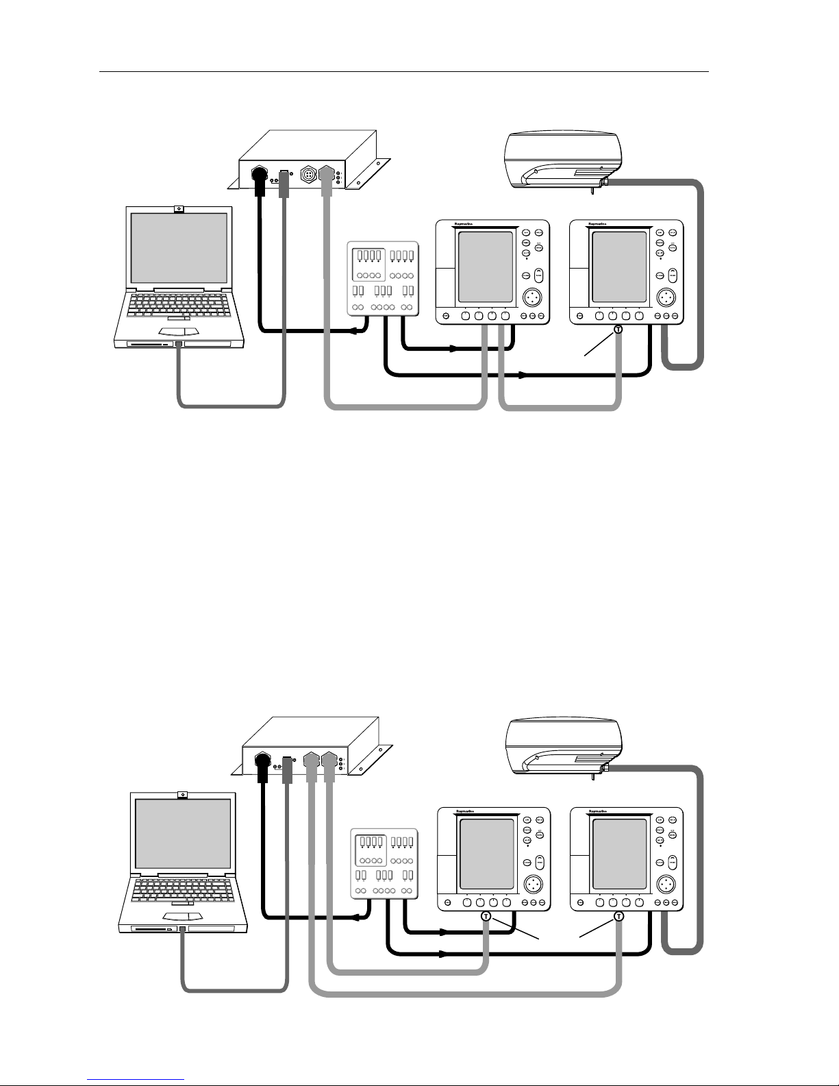
Toconnect the Interface Box to the Pathfinder display(s) or DSM(s), obtain the
appropriate 3-pin (Pathfinder side) to 4-pin (Interface Box side) hsb2cable(s) from
your authorized Raymarine dealer.:
•E65009 – hsb2Cable Assembly, 3-pin-to-4-pin, 3m
•E05016 – hsb2Cable Assembly, 3-pin-to-4-pin, 10m
Terminators
The hsb2network must beterminated on each end ofthe line. You can obtain hsb2
In Line Terminators (part number R58117) from your authorized Raymarine dealer.
The Interface Box provides an internal terminator atboth PORT 1 and PORT 2. You
must attach an hsb2terminator plug at the end of the hsb2cable where it connects
to the last Pathfinder display or DSM on the network. This applies to both networks
if both ports are used.
Driver Installation
1. Place the CD that has the AI-USB driver into the CD drive.
2. Connect the InterfaceBoxto an available USB 2.0 port on your host computer.
3. Turn onthe power supply tothe InterfaceBox.
4. Windows
®should detect the new hardwareand display the “Found New Hard-
ware Wizard” window. Click Next to automatically install the software.
5. Click “ContinueAnyway” if Windows displays “The software you are installing
for this hardware: AI-USB Firmware Loader has not passed Microsoft Logo test-
ing to verify its compatibility with Windows XP…”.
6. Click “Finish” when the computer reports “Complete the Found New Hardware
Wizard...”.
7. Windows may again display the “Found New Hardware Wizard” window to
install the second driver. Repeat Step 4 and 5.
If Windows does not show“Found New HardwareWizard” when you first connect
the Interface box to the host PC, you can manually install the drivers:

RayTech USB2 to hsb2InterfaceBox5
1. Copy the file AIUSB.INF to the C:\WINDOWS\INF subfolder.
2. Copy AIUSBLDR.SYS and AIUSBDRV.SYS to the C:\WINDOWS\SYSTEM32\
DRIVERS subfolder.
3. Reboot the computer.
Note:
Ifyou cannot view the listed subfolders under the Windows root directory, itmay be
thatthey arehidden. From Windows Explorer, selectTOOLS > FOLDER OPTIONS and click the
“Show hidden files and folders” radio button on the VIEW tab.
Network Configuration
Because the USB2 to hsb2Interface Box provides you with two separate hsb2network
connections, you can set up several different configurations:
Single Display
Whenyou are integrating the RayTech PC with a single Pathfinder display, connect
the cables as shown in the following figure. Install a terminator at the end of the
hsb2cable where it connects to the display.
Multiple Units on a Single Network
You can connect multiple Pathfinder displays and DSMs by linking them together
with hsb2cables asdemonstrated in the following figure. Install a terminator at the
end of the hsb2cable where it connects to the last unit on the network. Although the
following illustration only shows displays attached, you can also connect a DSM to
the network.
hsb2
USB2
hsb2PLUS Series Display
Inteface Box
Scanner
DC Power Supply
Distribution Panel
In-line
terminator
Raymarine
Power
10-36Vdc
PORT 2PORT 3
RECON
STATUS
USB
PORT 1

6RayTech USB2 to hsb2Interface Box
Multiple Units on Two Networks
By connecting a display to both PORT1 and PORT2 you place each display on a
separate hsb2network. Thismeans you can attach multiple displays and DSMs to
each network by linking them together with hsb2cables. Under normal
circumstances, if you have multiple displays and DSMs installed, you would
distribute the units equally between the two networks. The Interface Box links the
two ports into one contiguous hsb2network.
You must install terminators at the end ofthe hsb2cables that connect to the last
units on BOTH networks.The following figure demonstrates connecting one display
to each network.
hsb2
USB2 hsb2
hsb2PLUS Series Displayhsb2PLUS Series Display
Interface Box Scanner
In-line
terminator
DC Power Supply
Distribution Panel
Raymarine
Power
10-36Vdc
PORT 2PORT 3
RECON
STATUS
USB
PORT 1
hsb2
USB2 hsb2
hsb2PLUS Series Display
Interface Box Scanner
DC Power Supply
Distribution Panel
In-line
terminator
Raymarine
Power
10-36Vdc
PORT 2PORT 3
RECON
STATUS
USB
PORT 1

RayTech USB2 to hsb2InterfaceBox7
The following figuredemonstratesconnecting two units to each network, including
aDSM.Youmust install terminators at the end of the hsb2cables that connect to the
last unitson BOTH networks.
Using Multiple Interface Boxes
You can also incorporate multiple Interface Boxes within the hsb2network. Ifyou
have multiple units installed, distribute them equally between the Interface Boxes.
You must install terminators at the end of the hsb2cables that connect to the last
display orDSM on each side of the network. This configuration is demonstrated in
the following figure. For clarity, the power connection cables are not shown.
hsb2
hsb2
USB2
hsb2PLUS Series Display
Interface Box
DC Power Supply
Distribution Panel
In-line
terminator
In-line
terminator
Digital Sounder Module
Transducer
Raymarine
Power
10-36Vdc
PORT 2PORT 3
RECON
STATUS
USB
PORT 1

8RayTech USB2 to hsb2Interface Box
Raymarine Ltd,Portsmouth, Hampshire, UK PO6 3TD
Raymarine Inc. Nashua, NH03063-4219,USA
Document number: 81251-1
+44 (0) 23 9269 3611
1-800-539-5539
Date: November2004
hsb2hsb2
USB2
USB2
hsb2
hsb2
hsb2hsb2
Power
Pathfinder Display
Pathfinder Display
hsb2Transducer
Pathfinder Display
Interface Box
Pathfinder Display
Interface Box
Terminator
Power
Power Power
Pathfinder Display
Power Power
Power
Terminator
Digital Sounder Module
Raymarine
Power
10-36Vdc
PORT 2PORT 3
RECON
STATUS
USB
PORT 1
Raymarine
Power
10-36Vdc
PORT 2PORT 3
RECON
STATUS
USB
PORT 1
Other manuals for hsb2 Series
3
Table of contents
Other Raymarine Recording Equipment manuals