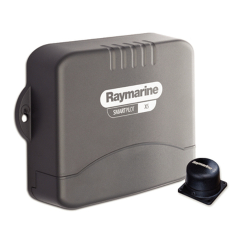
Raymarine SmartPilot X5 User manual

SmartPilot X5
Tiller&GPTiller
Installation&Setup
Guide
Documentreference: 87075-3
Date: August2008

Autohelm, HSB, RayTech Navigator, Sail Pilot,
SeaTalk and Sportpilot are UK registeredtrademarks of Raymarine UK Limited.
Pathfinder and Raymarine are UK registered trademarks of Raymarine Holdings Limited.
45STV, 60STV, AST, Autoadapt, Auto GST, AutoSeastate, AutoTrim,Bidata, G Series, HDFI,LifeTag, Marine Intelligence,Maxi-
view, On Board, Raychart, Raynav,Raypilot, RayTalk, Raystar, ST40, ST60+,Seaclutter, Smart Route, Tridata and Waypoint
Navigation are trademarks of Raymarine UK Limited.
All other product names are trademarks or registered trademarks of their respective owners.
© Handbook contents copyright Raymarine plc 2008

i
Contents
Preface ............................................................................................................................v
Safetynotices .......................................................................................................... v
EMCConformance .................................................................................................. v
Limitationsonpressure washing .............................................................................. v
Productdocuments ..................................................................................................vi
Warranty ..................................................................................................................vi
Productdisposal ......................................................................................................vi
WasteElectricalandElectronic(WEEE)Directive ...................................vi
Chapter 1:Installation and system overviews ................................................... 1
1.1 Installation overview .................................................................................... 1
Planning....................................................................................................... 1
Installing....................................................................................................... 1
1.2 Safe and successfulinstallation ................................................................... 1
Certifiedinstallation...................................................................................... 1
Gettingassistance........................................................................................ 1
1.3 Systemoverviews ....................................................................................... 2
Marineelectronics systems.......................................................................... 2
ExampleSeaTalksystem .........................................................................3
1.4 Equipment &Tools ....................................................................................... 4
Partssupplied .............................................................................................. 4
Toolsand equipmentNOTsupplied.............................................................. 5
Tools: ........................................................................................................5
Cables/equipment ...................................................................................5
Accessories.................................................................................................. 5
1.5 Createa schematic diagram ........................................................................ 6
Chapter 2:Installing the system ............................................................................. 7
2.1 Installation precautions ................................................................................ 7
EMC installationguidelines .......................................................................... 7
Remember ................................................................................................ 7
Suppression ferrites.................................................................................. 8
Connections to other equipment............................................................... 8
Compass .................................................................................................. 8
2.2 Generalcablingguidelines .......................................................................... 8
Power cable requirement ............................................................................. 8
2.3 SPX-5TillersystemCourseComputer ........................................................ 9
Mounting...................................................................................................... 9
X-5connectionoverview.............................................................................11
2.4 Install the Tiller Drive ...................................................................................11
Drivetype....................................................................................................11
Mounting requirements ...............................................................................11
Drive unit position................................................................................... 11
Step 1 - Mount theTiller Drive..................................................................... 13
Step 2 - Install the socket............................................................................ 15
Cablerequirement...................................................................................... 15
Fittingsocket.............................................................................................. 15

ii SmartPilot X-5 Tiller & GP Tiller Installation & Setup Guide
2.5 Adapting theinstallation ............................................................................. 16
Pushrodextension ..................................................................................... 16
Pushrodmounting...................................................................................... 16
Cantilever socket.................................................................................... 16
Pedestal socket...................................................................................... 17
Tillerbrackets.............................................................................................18
2.6 Connectingpower & drive cables to theCourse Computer ........................ 19
Power supply.............................................................................................. 19
Circuit breaker/fuse ................................................................................ 19
Cable...................................................................................................... 19
Connection procedure................................................................................ 20
2.7 Fluxgatecompass ..................................................................................... 21
Compass mounting .................................................................................... 21
Location..................................................................................................21
Mounting procedure................................................................................ 21
Compass connection.................................................................................. 22
2.8 PilotController ........................................................................................... 23
Fitting...................................................................................................... 23
Connecting to SeaTalk................................................................................ 23
SeaTalk power connections ................................................................... 23
2.9 Connect to ground ..................................................................................... 25
2.10 Optional connections ................................................................................. 26
Rudderreference .......................................................................................26
SeaTalkngConnections ............................................................................. 27
SeaTalkng power.................................................................................... 27
See also..................................................................................................27
NMEA 0183equipment .............................................................................. 28
Data bridging.......................................................................................... 28
NMEA 0183 / Connecting other manufacturers’ equipment................... 28
2.11 Finalchecks............................................................................................... 29
Secure all cables........................................................................................ 29
2.12 Commission the systembefore use ...........................................................29
Chapter 3:Commissioning & setup ......................................................................31
Requirement .............................................................................................. 31
3.1 Commissioning .......................................................................................... 31
Dockside checks& setup............................................................................ 31
Switching on........................................................................................... 31
Check SeaTalk and NMEA 0183 connections........................................32
SeaTalkinstruments................................................................................32
SeaTalk andNMEA GPS orChartplotter .................................................32
OtherNMEA 0183connections ..............................................................32
Checking autopilot operating sense ....................................................... 32
Setting the vessel and drive type............................................................33
Setthe vesseltype ..................................................................................34
Setthe drivetype.....................................................................................34
Align the rudder indicator........................................................................34
Set the rudder limits................................................................................ 34
Save the new settings ............................................................................35

Contents iii
Seatrialcalibration...................................................................................... 35
Important ................................................................................................ 35
Seatrial conditions.................................................................................. 35
Compass calibration............................................................................... 35
Swingingthe compass ............................................................................35
Aligningthecompassheading ................................................................37
AutoLearn............................................................................................... 38
Commissioningcomplete........................................................................... 40
3.2 Manualsetup ............................................................................................. 40
Checking SPX-5 Tiller system operation .................................................... 40
Response level........................................................................................... 41
Ruddergain................................................................................................ 41
Counter rudder .......................................................................................... 42
Checking................................................................................................. 42
Adjusting................................................................................................. 42
AutoTrim .................................................................................................... 43
Adjusting................................................................................................. 43
Chapter 4:SPX-5 Tiller system settings ............................................................. 45
4.1 Introduction ............................................................................................... 45
Calibrationmodes...................................................................................... 45
Display calibration .................................................................................. 45
User calibration....................................................................................... 45
Seatrial calibration.................................................................................. 45
Dealer calibration.................................................................................... 45
Accessing the Calibrationmodes ............................................................... 46
Adjusting calibration values........................................................................ 46
4.2 Displaycalibration ..................................................................................... 47
RUDD BAR screen..................................................................................... 47
HDGscreen ............................................................................................... 47
Data pages ................................................................................................ 47
Setting up data pages............................................................................. 48
4.3 User calibration ......................................................................................... 49
AutoTack.................................................................................................... 50
Gybe inhibit................................................................................................ 50
Windselection............................................................................................ 50
WindTrim.................................................................................................... 50
Response level........................................................................................... 50
4.4 Dealercalibration ...................................................................................... 51
Seatrialcalibrationlock .............................................................................. 52
Vesseltype ................................................................................................ 52
Drivetype .................................................................................................. 53
Alignrudder................................................................................................ 53
Rudderlimit ............................................................................................... 53
Ruddergain ............................................................................................... 53
Counter rudder........................................................................................... 53
Rudderdamping......................................................................................... 54
AutoTrim .................................................................................................... 54
Response level .......................................................................................... 54
Turn ratelimit.............................................................................................. 55
Offcourseangle......................................................................................... 55
AutoTackangle........................................................................................... 56
Gybe inhibit................................................................................................ 56
Windselection............................................................................................ 56

iv SmartPilot X-5 Tiller & GP Tiller Installation & Setup Guide
WindTrim ................................................................................................... 56
PowerSteer ................................................................................................ 56

Cruisespeed.............................................................................................. 57
Latitude...................................................................................................... 57
Systemreset .............................................................................................. 57
4.5 Systemdefaults ......................................................................................... 58
Appendix 1:NMEA 0183 sentences .................................................................... 59
NMEA0183to Course Computer................................................................ 59
NMEA0183 from Course Computer............................................................ 59
Appendix 2:SPX-5 Tiller system specifications .............................................. 61
CourseComputer ...................................................................................................61
Tiller Drive ..............................................................................................................62
Pilot Controller (ST6002) ........................................................................................63
Index..............................................................................................................................65

v
Contents
Preface
Safety notices
EMC Conformance
All Raymarineequipmentand accessories are designedto thebest industry
standardsfor usein the recreational marineenvironment. Their design and
manufactureconforms tothe appropriate Electromagnetic Compatibility (EMC)
standards, butcorrect installation is required to ensure that performanceis not
compromised.
Limitations on pressure washing
CAUTION: Do not pressure wash Raymarine products
Raymarine products must NOT be subjected to water pressures in
excess of CFR46 / IPX6 standards (for example, as generated by
commercial high pressure washing equipment). Products subjected
towater atthesehighpressuresmayexperiencewaterintrusionand
subsequent failure.
RaymarineproductsarewaterproofedtoCFR46/IPX6standards,whichmeansthat
when installed andoperatedin accordance with the appropriate product
documentation,theycanbeusedin mostweatherandseaconditions.However,any
exposureto high-pressure water that exceedsthe CFR46/ IPX6standards, on or
aroundRaymarine products will invalidate thewarranty for thoseproducts.
WARNING: Product installation & operation
This equipment must be installed, commissioned and operated
in accordance with the Raymarine instructions provided.
Failure to do so could result in personal injury, damage to your
boat and/or poor product performance.
WARNING: Switch off power supply
Make sure you have switched off the power supply before you
start installing this product.
WARNING: Navigational safety
Although we have designed this product to be accurate and
reliable, many factors can affect its performance. Therefore, it
should serve only as an aid to navigation and should never
replace commonsense and navigational judgement. Always
maintain a permanent watch so you can respond to situations
as they develop.

vi SmartPilot X-5 Tiller & GP Tiller Installation & Setup Guide
Product documents
Thisdocument is part of a series ofbooksassociated with the SPX-5 Tiller system.
Documentscanbedownloadedfromwww.raymarine.com/handbooks.
To the best ofour knowledge, theinformation inthe productdocuments was correct
when they went topress. However, Raymarine cannot accept liabilityfor any
inaccuraciesor omissionsinproductdocuments.
Inaddition,ourpolicyofcontinuousproductimprovementmaychangespecifications
withoutnotice. Therefore, Raymarinecannot acceptliabilityfor any differences
between theproduct and theaccompanying documents.
Warranty
To register your new Raymarineproduct, pleasetake afew minutesto fill outthe
warrantycard.It is important that youcomplete theowner information andreturnthe
card to usto receive full warranty benefits. You can also register online at
www.raymarine.com by followingthe
Login or create an account
link.
Product disposal
Waste Electrical and Electronic (WEEE) Directive
The EuropeanWEEE Directive requires that wasteelectrical and electronic
equipment is recycled.
Productscarryingthe crossed outwheeledbinsymbol(illustratedabove)
mustnot bedisposed of in general wasteor landfill, butin accordance withlocal
regulationsforsuchproducts.
Although theWEEE Directive does not applyto all Raymarine products, wesupport
itspolicy andask you tobe awareof the correct methodfor disposing ofsuch
products.
Pleasecontactyourlocaldealer,nationaldistributororRaymarineTechnicalServices
for information onproduct disposal.
Title Part number
SmartPilot X-5 Tiller and GP Tiller Operating Guide 81303
SmartPilot X-5 Tiller and GP Tiller Installation and Setup Guide 87075
ST6002 Controller installation sheet 87058
ST6002 SmartPilot Controller - Tiller Quick Reference Guide 86131
Fluxgate compass installation sheet 87011
Warranty Booklet 80017

1
Chapter 1: Installation and system overviews
Thischaptergivesanoverviewofinstallationproceduresandnetworkconfigurations
foran SPX-5 Tillersystem.
1.1 Installation overview
There are two stages toinstalling an SPX-5Tiller system,namely planning the
installation, then installing and mountingthe components.
It isimportant tocarry out the planningstage, toensure thatall componentsusedin
the system, including cablesand accessories,are correctlyspecified and located.
The following is a summary of the tasks in each stage.
Planning
1. Understandyoursystem.
2. Checkequipmentsupplied.
3. Establishsuitable locations for the autopilotequipment.
4. Plancablingandconnections.
5. Produceaschematicdiagram.
Installing
1. MountSPX-5CourseComputer.
2. Install Tiller Drive unit.
3. Install the autopilot controller.
4. Install the compass.
5. Connectpower cables and systemground.
6. Connectadditional equipment/ cables tothe Course Computer.
7. Finalfix: secure all equipment in place; secure allcables.
1.2 Safe and successful installation
To achieve a safe and reliable installation ofyour SPX-5 Tiller system,installation
mustbe carried out bya competent professionalwho shouldadhereto the
instructionsin thisguide.
Certified installation
Raymarine recommendscertified installation bya Raymarineapproved installer. A
certified installation qualifiesfor enhanced warranty benefits. Contact your
Raymarine dealer for further details and refer to theseparate warranty card packed
withyourproduct.
Getting assistance
If youneed further assistance withan installation, contact your dealer or visitthe
Raymarine web site
www.raymarine.com
.

2 SmartPilot X-5 Tiller & GP Tiller Installation & Setup Guide
1.3 System overviews
The SPX-5Tiller system consists ofa number of components connected together
using a Raymarine SeaTalk bus.
Marine electronics systems
The autopilot may form part of your wider ships electronicssystem. It may be
connected to equipment using a numberof marine industry standard protocols,
including:
• SeaTalk.
• SeaTalkng
• NMEA0183
D10510-1
Course Computer
SPX-5 Tiller system - key components
Drive unit
Fluxgate
compass
ST6002 Pilot Controller

Chapter 1: Installation and system overviews 3
Example SeaTalk system
SeaTalkallowsconnection of compatible instrumentsand equipmentthough a
dedicated databus.This allows information sharingaround the shipselectronics
system.
Depth
transducer
GPS
ST60+ depth
instrument
SeaTalk
cable
SeaTalk
cable
SeaTalk or NMEA
SeaTalk
cable
SeaTalk
cable
SeaTalk cable, carries:
- 12V power from Course computer
- Data to and from Course computer
SeaTalk
cable
ST60+ speed
instrument
Course computer
ST6002
SmartController
Speed
transducer
SeaTalk
3-way block
D10628-1
ST6002
SmartController
12 V dc

4 SmartPilot X-5 Tiller & GP Tiller Installation & Setup Guide
1.4 Equipment & Tools
Before you begin ensureyou have all thenecessary components andtoolsto install
your system.
Parts supplied
D10615-1
Mounting
socket
Tiller
pin
Plug
Socket screw
No 4 x 3/4 in (x2)
Tiller drive
Socket
6 mm drill bit
4 mm drill bit
Cable clip
and screw,
No 6 x 1/2 in
No 8 x 3/4 inch
Pan head screw (x3)
Connectors
SeaTalk Cable
Sun Cover
SmartPilot
ST6002
Controller
Panel Seal
Cable tie
Stud (x2)
Finger
Nut (x2)
Course
Computer
Bracket screw,
No 10 x 3/4 in (x4)
Compass
warning label
Fluxgate compass
with 8 m (26 ft) cable User documents
in wallet

Chapter 1: Installation and system overviews 5
Tools and equipment NOT supplied
Youwillneedtosupplythe followingequipmentandtools:
Tools:
• Drill
• 2.5 mm(3/32"),6 mm(1/4"), 12.5mm (1/2"), 18 mm (23/32") drillbits
• Two-partepoxy(Araldite)adhesive
• Cross-head/pozi-drive screwdriver
• Slotted-head screwdriver
Cables / equipment
• Powercableandfuse/breaker.See
page 19
.
• Additional datacables(e.g. for connection of GPS orchartplotter)
• Grounding braid. See
page 25
.
Accessories
The followingaccessories maybe usedto adaptthe tiller drive mountingto suit
different installation requirements.See
Adaptingtheinstallation
on
page 16
.
Part Number Description
D001 Tiller Pin (package of 5)
D002 Mounting Socket (package of 5)
D003 Pushrod Extension 25 mm(1")
D004 Pushrod Extension 51 mm(2")
D005 Pushrod Extension 76 mm(3")
D006 Pushrod Extension 102 mm(4")
D007 Pushrod Extension 127 mm(5")
D009 Tiller Bracket 25 mm(1")
D010 Tiller Bracket 51 mm(2")
D011 Tiller Bracket 76 mm(3")
D014 Small threaded tiller pin 25 mm (1")
D014 Small Thread Tiller Pin (package of 5)
D020 Extra length tiller pin 71 mm (2.8”)
D021 Extra length threaded tiller pin 71 mm (2.8”)
D026 Pedestal Socket 38 mm(1.5")
D027 Pedestal Socket 51 mm(2")
D028 Pedestal Socket 64 mm(2.5")

6 SmartPilot X-5 Tiller & GP Tiller Installation & Setup Guide
1.5 Create a schematic diagram
AspartofthepreparationforinstallingyourSPX-5Tillersystem,werecommendthat
youcreateaschematicdiagramrepresentingthesystemyouwantto install.Thiswill
help ensurethat youinstall asafe optimumsystem, and sois particularlyimportant if
you intendconnectingyour autopilot toother electronicequipment.
The schematic diagram should include:
• Locationof all components.See
pagev
and
page7
forEMC guidelines that may
affect the locationof specific components.
• Connectors, cabletypes,routesandlengths.
When you have completed the schematic diagram, you are ready to begin installing
theSPX-5 Tillersystem.
Part Number Description
D029 Pedestal Socket 76 mm(3")
D030 Pedestal Socket 89 mm(3.5")
D031 Cantilever Socket
D159 Tiller Bracket 102 mm(4")
D160 Tiller Bracket 127 mm(5")

7
Chapter 2: Installing the system
Before proceeding with the installation you shouldhavethe following to hand:
• All necessaryequipment andtools toinstall your SPX-5Tiller system.
• The correct type and length ofpower cable.
• Schematic diagram detailingautopilot system location and connections.
Youshouldalsocheckthatexistingmarineelectronics,suchastheGPSareinstalled
andworking.
2.1 Installation precautions
CAUTION: Switch off power supply
Switch off the power supply before you start installing this product.
EMC installation guidelines
RaymarineequipmentandaccessoriesconformtotheappropriateElectromagnetic
Compatibility (EMC) regulations. This minimizeselectromagneticinterference
between equipment,which could otherwiseaffectthe performance ofyour system.
Correctinstallation is required toensure that EMC performance is not compromised.
ForoptimumEMC performance,werecommendthat:
• Raymarineequipmentand the cablesconnected toit are:
i. Atleast3ft(1m)fromanyequipmenttransmittingorcablescarryingradiosig-
nalse.g.VHFradios,cablesandantennas.InthecaseofSSBradios,thedis-
tanceshould beincreasedto 7 ft (2 m).
ii. Morethan7ft(2m)fromthepathofaradarbeam.Aradarbeamcannormally
beassumedto spread 20 degrees above andbelow theradiating element.
• The product is supplied froma separate battery fromthat used for engine start.
This is important topreventerraticbehavior and datalosswhich can occur if the
engine start does not have a separate battery.
• Raymarinespecifiedcablesare used.
• Cablesare not cutor extendedunlessdoingso isdetailedin theinstallation
manual.
Remember
Where constraints onthe installation prevent any ofthe above recommendations:
• Always allow themaximumseparation possiblebetween different itemsof
electrical equipment. Thiswillprovide the best conditions forEMC performance
forthe installation.
WARNING: Install at dockside
For safety reasons your boat must be at dockside before
commencing installation.

8 SmartPilot X-5 Tiller & GP Tiller Installation & Setup Guide
Suppression ferrites
Raymarine cablesmay befittedwith suppression ferrites. Theseare important for
correct EMC performance. Any ferrite removed to facilitateinstallationmustbe
replaced inthe originalposition immediately afterthe installationis complete.
• Use only ferrites of the correcttype, supplied by Raymarine authorized dealers.
Connections to other equipment
If Raymarineequipment is tobe connected to other equipment using acable not
supplied byRaymarine,a Raymarinesuppressionferrite MUSTalwaysbe attached
to thecablenear theRaymarine unit.
Compass
Thecompassis sensitivetomagneticinfluences and otherpotentialsourcesof
interferenceincludingenginesandVHFradiowaves.Toensureoptimumoperationit
is essentialto locate the compass correctly.
2.2 General cabling guidelines
• Do not mix ac and dc cables.
• Adhere to EMC guidelines(see
page7
).
• UseCopexconduitwhereappropriateto protectcables.
• Labelall cables for easyidentification.
• Keep the Fluxgate compass cableseparatefrom othercables.
Power cable requirement
An overview of the power cables isgivenin the following illustration.
D10624-1
Distribution
panel
Course
Computer
Tiller Drive
unit
Cable A
Cable B
Cable C

Chapter 2: Installing the system 9
CAUTION: Power cable
Using an incorrect size of power cable could reduce the power
supplied to the drive unit and therefore cause your SPX-5 Tiller
system to malfunction. Ensure the correct cable size is used. If in
doubt, use a heavier gauge cable.
The requirement forpower cables dependson thetotal length ofthe power circuit.
That is thetotal length ofCableA + Cable B +Cable C.
The correctcable dimensionsfor various cable lengthsare given in thefollowing
table.
2.3 SPX-5 Tiller system Course Computer
Mounting
The Course Computer must bemounted ona secure vertical surface, free from
vibration.
Total cable length (A + B + C) Copper area AWG
Up to 2.5 m (8 ft) 1.0 mm218
Up to 4.0 m (13 ft) 1.5 mm216
Up to 6.0 m (22 ft) 2.5 mm214
or
Min
Max
-10
55
14
130
°F°C
10° 10°
D10629-1

10 SmartPilot X-5 Tiller & GP Tiller Installation & Setup Guide
D10375-1
MOUNT
VERTICALLY
170 mm (6.7 in)
237 mm (9.33 in) 56 mm
(2.2 in)

Chapter 2: Installing the system 11
X-5 connection overview
The X-5course computer providesthe following system connections.
2.4 Install the Tiller Drive
Drive type
The correctTiller drive unit type isdependenton thefully laden displacement ofthe
vessel.
• For vesselsup to 6 tonnesfully laden displacement, usethe standard tiller drive.
• For vesselsup to 7.5tonnesfully laden displacement, use theGP tiller drive.
Note:
The actual laden displacement for a vessel can be up to 20% greater than the manufac-
turer’s published displacement figures.
Mounting requirements
TheTillerDrivemustbemounted:
• Horizontally.
• So thatwhen the tilleris centered,the drive axisis at 90degrees tothe tiller axis.
Drive unit position
The tiller pin anddrive socketcan bemounted between356 mm and 457 mm (14” -
18”) fromthecentre ofthe rudder stock.
Forquickerrudderresponsein vesselsrequiringfasterturnrates(e.g.lighter
displacementvessels),install thetiller pinand drivepedestal closer tothe rudder
stock, to aminimum of 356 mm (14").
152
A B
Fluxgate
compass inputs
Rudder position
sensor inputs
SeaTalk
inputs/outputs
Power
inputs
(12 V)
RF ground
connection
NMEA 0183
input/ouput
SeaTalkng
inputs/outputs
Drive motor
outputs
D10374-1
SeaTalk fuse
(2 A)
Power fuse
(15A)
Note: Spare fuses
are located in the
connector cover

12 SmartPilot X-5 Tiller & GP Tiller Installation & Setup Guide
Use thefollowing tableto determinethe required positionfor your vessel.
The Tillerdrive mounting arrangement is shown in the followingillustration. In the
following,dimensionArepresentstherequireddistancebetweenthetillerpinandthe
centerof therudder stock,as determinedfrom the above information.
Drive pin
distance from
rudder stock
Max degrees of
helm (with pilot
engaged)
Rate of helm
change Force at rudder
457 mm (18”)
standard distance 31º 8 º per second 84 kgf
432 mm (17”) 33º 8 º per second 79 kgf
406 mm (16”) 35º 9 º per second 75 kgf
381 mm (15”) 37º 9 º per second 70 kgf
356 mm (14”) 39º 10 º per second 65 kgf
620mm (24.5")
620mm (24.5")
D10649-1
Dimension A
Dimension A
90o90o
620mm (24.5")620mm (24.5")
Other manuals for SmartPilot X5
2
Table of contents
Other Raymarine Tiller manuals
Popular Tiller manuals by other brands

Oypla GARDEN
Oypla GARDEN 3073 user manual

Craftsman
Craftsman 247.23000 Operator's manual

Troy-Bilt
Troy-Bilt GARDEN WAY Pro line 12183 owner's manual

Powermate
Powermate PCV43 Operator's manual

Classen
Classen STAND-AER SA-25 Operator's manual and parts list

Garland
Garland MULE 1162 NRQG-V20 instruction manual