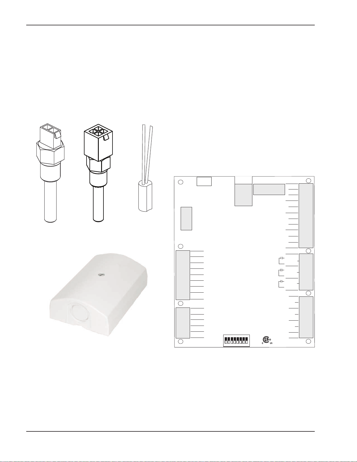
Raypak VERSA IC Manual

INSTALLATI N & PERATING
INSTRUCTI NS
Catalog No. 5000.72 Effective: 11-01-14 Replaces: 08-18-14 P/N 241493 Rev. 3
VERSA IC
Integrated Boiler Control
®

2
Rev. 2 is a software revision J1214G ( ug 2014) completely new edition of this manual.

3
WARNINGS
WARNING: Improper installation, adjustment,
alteration, service, or maintenance can cause
property damage, personal injury or loss of life.
Refer to the user's information manual provided with
the heater. Installation and service must be
performed by a qualified installer, service agency, or
the gas supplier.
WARNING: Risk of electrical shock. More than one
disconnect switch may be required to de-energize
the equipment before servicing.
WARNING: When servicing or replacing any
components of the control system within this unit, be
certain that:
• The gas is off.
• ll electrical power is disconnected.
Table f Contents
W RNINGS...........................................................3
Introduction............................................................4
VERS ®Control Board.........................................4
VERS ®Display Board ........................................5
VERS ®PIM™ Module ........................................6
Quick Start Set-Up and Programming Tips...........8
pplication & Modes .............................................9
Boiler pplications.................................................9
Hydronic Mode 1...................................................10
Hydronic Mode 2...................................................15
Hydronic Mode 3...................................................21
Water Heater pplications.....................................27
Pool Heater pplications .......................................32
VERS IC®Control Menus ..................................36
Control Settings.....................................................41
Cold Water Protection (CWP) ...............................43
Heater Rotation .....................................................46
Sequence of Operation .........................................48
Wiring Connections – PIM™.................................50
Wiring Connections – VERS IC®Control............55
Energy Management System Setup .....................56
Cascade Set-up and Operation ............................57
“Limp- long” Operation of PIM™..........................62
Troubleshooting.....................................................63
Technical Data.......................................................66
Resetting VERS ®to Factory Defaults ................67
Resetting PIM™ to ccept New ID Card ..............67
Modbus Communication Values............................69
Table Of Figures....................................................76
List Of Tables ........................................................77

4
Introduction
The Raypak VERS ®IC is an appliance integrated
control system consisting of the following components:
• VERS ®Control Board
• VERS ®Display Board
• VERS ®Platform Ignition Module (PIM)™ in HSI,
DSI or Supervised Pilot Ignition
• ID Card
• Water Sensors (up to 5)
• Vent Sensor
• Outdoor ir Sensor
The VERS IC®control system provides integrated
functions of automatic ignition control, thermostat con-
trol, high temperature limit control, diagnostic
enumeration, safety interlock, domestic hot water
(DHW) override, Cold Water Protection (CWP) and
several options for external heater control for Raypak
commercial boilers, water heaters and pool heaters.
The VERS IC®control system controls the heater
pump, system pump and indirect DHW pump simulta-
neously as needed.
VERSA®Control Board
The VERS ®Control Board provides high-level func-
tionality for the VERS IC®control system. It has field
interlock connections, cascading heater connections
and VERS ®Display Board connections. The VERS
IC®control system allows “limp-along” operation via
the PIM™ if the VERS ®Control Board becomes
inactive or if the communications between the
VERS ®Control Board and the PIM™ are terminated
for any reason. This “limp-along” mode operation is
outlined in more detail starting on page 62. The
VERS ®Control Board is NSI Z21.23 certified as a
controller.
In addition, the VERS IC®control system allows cas-
cading control of multiple units up to 4 units total
without the need for an external sequencer. The
VERS IC®control system is Modbus ready for easy
external communication and control.
Fig. 1: Water Sensors
Fig. 2: Outdoor Air Sensor (S4)
Raypak
VERSA
#013935F
Designed and assembled in Canada
158033
ON
1 2 3 4 5 6 7 8
Condensate Switch
Vent Temp Limit
Auto High Limit
Low Water
Blocked Vent
Low Gas Press
High Gas Press
(Extra)
CN5
Water Flow Switch
Blower Air Switch
Factory Option 3
Factory Option 2
Factory Option 1
CN8
LED Out
Diagnostics
Power On
Call For Heat
Burner On
Service
CN6
1049-01
PIM 2
Ft_Bus
A
B
PIM 3
Ft_Bus
A
B
PIM 4
Ft_Bus
A
B
GND
CN2
F6018C
Fan /
Damper
CN4
R
Com
S6
RS485-A
RS485-B
Mod +
GND
GND
GND
ModBus-A
ModBus-B
CN1
CWS/CWR
Remote LCD
CN7
S7
Extra
External
Valve
Power: 24 V (ac) ± 10% 50/60 Hz 5.2 VA 215 mA
Relays: 240 V (ac) 5 A
CN3
Fig. 3: VERSA®Control Board
INLET (S2) OUTLET (S1)
FIELD
INST LLED
(S5, S6, S3)

5
The VERS ®Control Board includes connections for:
• LED Indicator Lights (model specific)
o Green – POWER ON
o mber – C LL FOR HE T
o Blue – BURNER ON
o Red – SERVICE REQUIRED
• Diagnostic Inputs
o Condensate Switch
o Vent Temperature Limit
o uto High Limit
o Low Water Cutoff
o Blocked Vent
o Low Gas Pressure
o High Gas Pressure
o Extra – (future usage)
o Water Flow Switch
o Blower ir Switch (model specific)
o Factory Option 1 – Factory Define
(10 - second delay)
o Factory Option 2 – Factory Defined
(30 - second delay)
o Factory Option 3 – Factory Defined
(90 - second delay)
• Cascade Communication Connections (Ft_bus
Communication)
o PIM™ 2 – & B
o PIM™ 3 – & B
o PIM™ 4 – & B
• External Device Triggers (dry contact)
o External Valve
o Fan/Damper
o Extra - status (burner)
• uxiliary Sensor Inputs
o S6 – IND Supply Sensor/Pool Return Sensor
o S7 – N/
• 0-10 VDC Output (Cold Water Protection)
o Mod+/-
• Communication Connections
o RS485 (future usage)
o Modbus RS485 (RTU/ SCII)
• VERS ®Display Connection (Ribbon Cable)
• VERS ®PIM™ Connection (RJ45 Connection)
•DIP Switches
o #1 – ccess Level
•FF – Installer
• ON - dvanced
o #2 – Cascading
• OFF – Follower/Slave
•N – Master
o #3 – Cold Water Protection
•FF – None
• ON – CWS/CWR
o #4 – Proportional Output Selection
•FF – 0-10 VDC
• ON – 0-20m (requires 500 ohm resistor)
o #5 – Remote Display (RS485)
•FF
• ON
o #6 – Heater Rotation (see page 46)
•FF – No Rotation
• ON – Enable Rotation
o #7 – TBD
o #8 – TBD
Fig. 4: VERSA®Control Board DIP Switches
VERSA®Display Board
The VERS ®Display Board is the board with the LCD
display viewable from outside of the heater. ll opera-
tion and settings of the VERS IC®control are
accomplished through the use of the 5 buttons of the
user interface. These buttons are labeled as follows:
• ENU – Scroll through available menus
• ITE – Scroll items within the selected menu
• UP – Increase values in the Adjust menu
• DOWN – Decrease values in the Adjust menu
• RESET – Clear lockout
Fig. 5: VERSA®Display Board

6
The display uses a Liquid Crystal Display (LCD) as the
method for supplying information. Use the LCD to
setup and monitor the operation of your heater.
If the membrane switch remains inactive for 180-sec-
onds (3 minutes), the screen will revert to the VIEW
menu – Boil INLET unless some error/fault exists –
then the fault will be displayed. Touching any button
resets this timer (the timer can be seen in the bottom
right corner of the display) to keep the current view.
Fig. 6: Display
The VERS ®Control Board has 2 access levels:
Installer and dvanced. Most settings are hidden in
the Installer mode. The dvanced mode can be
accessed by changing the VERS ®DIP switch #1
from the “OFF” position (Installer) to the “ON” position
( dvanced).
The default menu displayed is the VIEW menu. If
there is an unresolved (active) error, then the default
menu is the TOOLBOX menu. The default item will be
the active error message. fter 180-seconds of key-
pad inactivity, the VERS ®Display will return to the
default menu and display the default item.
VERSA®PIM™ Module
The PIM™ (Platform Ignition Module) is available in
DSI (Direct Spark Ignition), or HSI (Proven Hot
Surface Ignition) versions depending on Raypak
model type.
The PIM™ integrates the functions of utomatic
Ignition Control with temperature regulating and con-
trol functions. The PIM™ is designed for a range of
boilers, water heaters and pool heaters including
ON/OFF, staged and modulating types. The PIM™ is
intended to provide safe lighting and supervision of the
burners in a heater.
The PIM™ is also designed to connect to and receive
commands from the VERS ®Control Board for high-
er-level functionality to include indirect DHW, outdoor
reset, diagnostic messaging, and other system capa-
bilities. Communication is accomplished using a
proprietary protocol on the Ft_bus.
The PIM™ is CS certified to the NSI Z21.20
Standard for Thermostats and utomatic Gas Ignition
Systems and Components and C N/CS C22.2 No.
199-M99. The VERS ®PIM™ also complies with the
UL372 Primary Safety Controls for Gas and Oil Fire
ppliances (Harmonized version); UL 1998 Software
in Programmable Components, 2nd edition and UL
353 Limit Controls.
The PIM™ provides standard support for 10k ohm @
77°F NTC curve J Thermistor probes. The Inlet and
Outlet/Hi-Limit sensors are directly processed by the
PIM™. The System, Outdoor, and DHW tank sensors
are also connected to the PIM™ but are passed
WARNING: Return the VERS ®control DIP
switch #1 to the “OFF” (Installer) position after
heaters are fully set up and commissioned to prevent
inadvertent changes to program settings by unau-
thorized personnel.
J5
J6
J7
J8
J9
J10
J11
J12
J14
RESET
POWER
ALARM/TEST
FAULT
FS GND
J4
L1 15A
BLOWER
OPTION
BLOWER
19110
OPERATOR
SET
POINT
FIELD OPTIONS
SEE MANUAL
J15 REMOTE LED
FC-
FC+
T3
J2 J1
F1
P2
J3
Fig. 7: VERSA®DSI PI ™ odule

7
Icon When Displayed
VIEW Menu = View
SETUP Menu = Setup
BOILER Menu = Boiler View Menu of Boiler 1,
2, 3 or 4
BOILER 1 Menu = Boiler View Menu of Boiler 1
BOILER 2 Menu = Boiler View Menu of Boiler 2
BOILER 3 Menu = Boiler View Menu of Boiler 3
BOILER 4 Menu = Boiler View Menu of Boiler 4
MONITOR Menu = Monitor
M
Single boiler or
Master Boiler in Cascade
Menu = View, Solid if Installer ccess
Level
Flashes at 1Hz if OEM ccess Level
Menu = Toolbox
WWSD Warm Weather Shutdown is active
Menu = View, Flashes at 1 Hz if one of
the connected PIMs is in Lockout
Menu = View, Solid if there is a known
active error on one of the connected
PIMs
Calls Menu = View/Test
Heat Menu = View/Test and Heat Call present
DHW Menu = View/Test and DHW Call present
Pool Menu = View/Test and Pool Call present
Tank Menu = View/Test and Tank Call present
Mixing Shown whenever Cold Water
Protection is enabled (VERS ®DIP 3).
Setpoint Menu = View/Test and Setpoint Call
present
Icon When Displayed
Pumps Menu = View/Test
Boiler
Pump Menu = View/Test and Boiler Pump is on
System
Pump Menu = View/Test and System Pump is on
DHW
Pump Menu = View/Test and DHW Pump is on
Burner Menu = View/Test
1 Menu = View/Test and PIM™ 1 is on
2 Menu = View/Test and PIM™ 2 is on
3 Menu = View/Test and PIM™ 3 is on
4 Menu = View/Test and PIM™ 4 is on
(Burner
Rate) %
Menu = View/Test and PIM™ is modu-
lating. Displays current plant firing
rate.
ModBus Menu = View and ModBus communi-
cation is present
°C
Whenever the item displayed in the
number field is a temperature and
UNITS = degC
°F
Whenever the item displayed in the
number field is a temperature and
UNITS = degF
min Whenever the item displayed in the
number field is in minutes
hr Whenever the item displayed in the
number field is in hours
sec Whenever the item displayed in the
number field is in seconds
µ Whenever the item displayed in the
number field is in micro-amps
%Whenever the item displayed in the
number field is in percent
RPM Whenever the item displayed in the
number field is in RPM
Table A: VERSA®Display Symbol Descriptions

8
PIM™ DIP Switches
There is an 8-position DIP switch on the PIM™ that
can be field configurable during commissioning. The
UP position is “ON” and the DOWN position of each
DIP switch is “OFF”. The items in BOLD below repre-
sent factory defaults settings.
DIP Switch #1 – Operator Differential
ON = Manual Differential
OFF = Auto Differential
DIP Switch #2 – nalog Input Type
ON = Direct Drive
OFF = Target Temperature
DIP Switch #3 – Pump Post Purge
ON = Pump Post Purge Active
OFF = Pump Post Purge Inactive
DIP Switch #4 – Pump Exercise Enable
ON = Pump Exercise Active
OFF = Pump Exercise Inactive
DIP Switch #5 – EMS/Demands
ON = EMS nalog Input Only
OFF = VERSA IC®Demands Only
DIP Switch #6 – EMS Signal Type
ON = 4-20m *
OFF = 0-10 VDC
DIP Switch #7 – Freeze Protection
ON = Freeze Protection Active
OFF = Freeze Protection Inactive
DIP Switch #8 – Commission Test
ON = Commission Test ctive
OFF = Commission Test Inactive
*NOTE: 4-20m operation requires the use of an
external 500Ω, 1/2W resistor.
PIM™ perator Set-Point Dial
The PIM™ has a set-point dial that is used to deter-
mine the operator set-point applied to the boiler outlet
sensor during “limp-along” operation of the VERS
IC®Control System. The default position of the opera-
tor set-point applied to the boiler outlet sensor dial is
the maximum set-point, which is defined by the PIM™
parameters defined by the ID card. The dial can be
adjusted down to a user-defined level between the
minimum setting of 70°F or the maximum allowed by
the ID card. This function is only active during
“limp-along” operation.
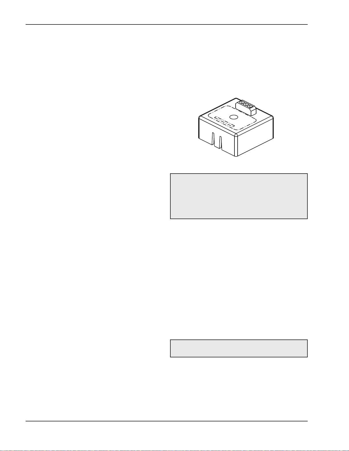
VERSA IC®Unit Type ID Card
The VERS IC®Identification Card (ID Card) is a small
circuit card that determines the operating parameters
for each individual model by unlocking the correct pro-
gram within the VERS ®Platform Ignition Module
(referred to simply as PIM™ throughout the rest of this
manual). It is permanently affixed to the chassis of the
heater and MUST be present for the heater to operate.
DANGER: In the event of ID Card failure, field
replacement can only be performed by a Raypak
Employee or contracted Representative and must be
replaced with an ID Card of the same number.
Serious risk of severe personal injury, death or sub-
stantial property damage if not correctly serviced.
Fig. 8: VERSA®PI ™ ID Card
through to the VERS ®Control Board which is
required to provide those additional functions. uxiliary
sensors, such as the indirect supply / pool return sen-
sor, connect directly to the VERS ®Control Board for
other enhanced functions depending on the mode
selected. For detailed wiring information, refer to the
I&O Manual for the product being installed.
Quick Start Set-up &
Programming Tips
1. Determine the piping arrangement for your partic-
ular application by referencing the pplication
drawings and descriptions on pages 9 to 34.
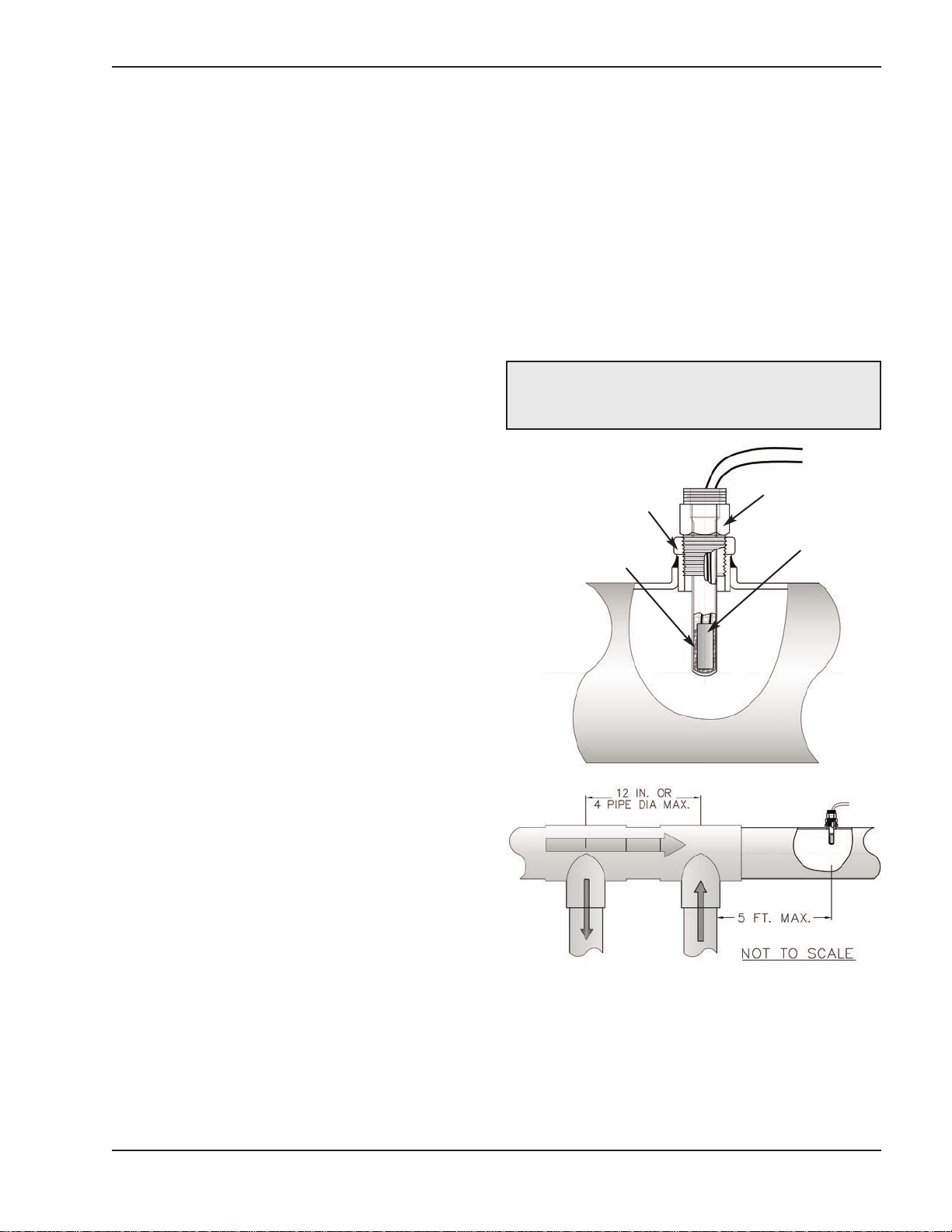
2. Install the System Sensor, Outdoor/ ir Sensor,
Indirect DHW Sensor as necessary as depicted in
the above referenced pplication drawing.
3. Wire the sensors to the VERS IC®system as
described on the wiring diagram of the respective
model (see model I&O wiring diagrams). Sensor
wires should be routed to the heater in separate
conduit.
CAUTI N: Sensor and control wiring must NOT be
run in conduit or chases with line voltage.

9
4. Ensure that the entire system is ready for opera-
tion.
a. Water piping properly filled and purged of air?
b. Gas pipe properly installed and purged?
c. Electrical connections properly installed?
d. For cascading systems:
i. re communication wires properly
installed between Follower PIM™s and
the Master VERS IC®Control? (see
page 57)
ii. re the DIP switches properly set for
Master/Follower operation?
e. Vent properly installed and terminated?
f. Sensor wires properly routed in separate con-
duit?
g. External interlocks properly installed and
wired to VERS IC®Control (louver interlock,
extractor, external gas valve, etc.)?
5. For CWP (Cold Water Protection) Systems
i. re the actuators properly installed?
(Refer to CWP configuration page 43)
ii. Is VERS ®DIP #3 turned on?
6. Turn on system electricity to allow programming
the VERS IC®Control to be programmed.
7. For H models go to the ADJUST menu and set the
heater ODE as indicated on the pplication
drawing – 1, 2 or 3. (Mode 1 is for “Stand- lone”
or cascade heaters with no Indirect DHW needs;
Mode 2 includes Indirect DHW in the system loop;
and Mode 3 includes Indirect DHW in the boiler
loop). WH and P models do not require a mode
selection as they are configured only for direct
DHW or pool heating operation.
8. Use the pplication drawings and descriptions as
a guide to set up the control.
9. change to a value will be made as soon as you
push the ITE button, change the ENU screen,
or wait until the 180-second timer expires.
10. Should any error be displayed, check the
Troubleshooting Section to identify the source of
the error and recommended troubleshooting
ideas.
System Sensor Installation
The System Sensor (S3) is required for all selectable
modes unless the units firing rate will be controlled by
an external source such as our Temp Tracker MOD+
Hybrid sequencer. Proper placement and method of
installation are critical for proper operation of the sys-
tem. The sensor must be installed in a drywell in
conjunction with heat conductive compound as
shown in the following images. The drywell must be
installed no more than 5 equivalent feet of pipe/tub-
ing downstream of the de-coupler and installed in
such a way that ensures the sensor bulb is in the
flow path.
CAUTI N: Be careful when installing the drywell
not to over-tighten the well as this can damage the
well and may prevent the sensor from fitting properly.
Fig 9: System Sensor Installation
System
Sensor
Thermal
Paste
Drywell
NPT
Fitting

10
A
B
AB
Fig. 10: ODE 1, Hydronic Single Boiler
Fig. 11: ODE 1 Hydronic Single Boiler, CWP (BOIL 3-Way)
M DE 1 Single
Maximum distance not to exceed 4 pipe
diameters or 12” whichever is less
Maximum distance not to exceed 4 pipe
diameters or 12” whichever is less
A
B
AB
GY
(+ MOD)
BK
(COM)
R
(+ 24V C)
CWP Valve detail

11
Applications & Modes
The VERS IC®Control system is designed for a wide
range of applications. The installer/design engineer
should refer to the following drawings for configura-
tions currently supported by the VERS IC®Control
system to determine which most closely resembles the
intended/installed system configuration. Refer to the
section(s) of this manual for instructions outlining the
piping layout, sensor locations and settings for best
operation of the specific configuration shown.
Hot water heating systems all have unique levels of
operating diversity that must be accounted for in the
system design. The system should always include
adequate system flow in excess of the connected boil-
er flow for proper operation. Where the system flow
may drop below the connected boiler flow, a
buffer/decoupler may be needed. Failure to design for
adequate flow (i.e. bypasses, 3-way control valves,
flow limiting balance devices, buffer tanks, etc.) will
result in boiler short cycling and may reduce boiler life.
lways contact your local Raypak representative for
system design assistance to avoid these issues.
M DE 1 Hydronic Systems
without Indirect DHW
This section covers single- or multiple-boiler installa-
tions used for individual hydronic heating systems
without indirect DHW. The following diagrams will
show single-boiler systems with and without CWP. The
CWP diagrams will show an individual 3-way valve at
the boiler (MIX Type = BOIL). The following piping con-
figurations can be used as fixed set-point or set up to
work in conjunction with an Outdoor ir Reset Sensor
(S4) to adjust the target water temperature as the out-
door air temperature changes.
M DE 1 Single
Primary/secondary piping is the only method support-
ed by Raypak to ensure proper boiler and system
functionality while achieving maximum system efficien-
cy.
The boiler firing rate will be controlled by the System
Sensor (S3). See System Sensor Installation on
page 9. The VERS IC®will provide Max Delta T
(Differential Temperature) control and will cycle the
burner if the Max Delta T is exceeded between Boiler
Outlet Sensor (S1) and Boiler Inlet Sensor (S2).
In order to enable MIX settings, VERS ®DIP #3 must
be set to ON position. Raypak’s Cold Water protection
system utilizes a proportional 3-way valve to bypass
water from the boiler outlet to the inlet during opera-
tion, when the system return water temperature is
below the minimum acceptable level as defined in the
Installation and Operating manual for the product
being installed.
The Boiler Pump (P1) runs during any call for burner
operation and is delayed “off” as user-defined in the
BOILER menu after the burner has shut down. The
System Pump (P2) runs whenever the system is
enabled for heating and the outdoor air temperature is
lower than the WWSD temperature setting (if utilized).
The System Pump is delayed “off” as user-defined in
the SETUP menu. MODE 1 is used for this configura-
tion. See SETUP menu items in Table B page 15. This
configuration supports BMS 0-10 VDC input for tem-
perature or rate control and can be configured for
connectivity to BMS via the onboard Modbus port cov-
ered later in this manual.
Ensure DIP switch #1 and 2 on the VERS Control
Board are in the ON position to make programming
changes. Prior to setting any DIP switches, the heater
must be turned off.
M DE 1 Cascade
The following diagrams will show cascade systems (up
to 4 boilers maximum) with and without CWP. The
CWP diagrams will show either an individual 3-way
valve at the boiler (MIX Type = BOIL) or a single 3-way
valve providing CWP to all connected boilers within the
cascade (MIX Type = PLNT). The following piping con-
figurations can be used as fixed set-point or set up to
work in conjunction with an Outdoor ir Reset Sensor
connected to the Master unit (S4a) to adjust the target
water temperature as the outdoor air temperature
changes.
Reverse/return piping is shown and is recommended
to ensure balanced flow through each of the connect-
ed boilers. Primary/secondary piping is the only
method supported by Raypak to ensure proper boiler
and system functionality while achieving maximum
system efficiency.
N TE: 0-10VDC firing rate control ignores all
functions except Limit/and Safety Switches, Max
Delta T and CWP.
N TE: “a” designation represents connection is at
Master boiler “ ”
CAUTI N: Continous pumping through the unit is
not supported and may cause a non-warranty failure.

12
MASTER
MASTER
A
B
AB
Fig. 12: ODE 1 Hydronic ulti-Boiler
Fig. 13: ODE 1 Hydronic ulti-Boiler ( IX TYPE = BOIL)
Maximum distance not to exceed 4 pipe
diameters or 12” whichever is less
Maximum distance not to exceed 4 pipe
diameters or 12” whichever is less

A
B
AB
MASTER
13
Fig. 14: ODE 1 Hydronic ulti-Boiler ( IX TYPE = PLNT)
MVB®/ XTherm®, or the PIM J2 terminal block. Each boil-
er in the cascade connects to and controls its own
respective Boiler Pump (P1a-b-c-d). The System Pump
(P2a) gets its enable signal from the Master boiler. It is
important to remember to enable a boiler to be a follower
in the cascade by turning DIP switch #2 on the VERS ®
Control Board to the “OFF” position for each of the follow-
ers. Once the followers have been configured correctly
you must then enable the followers within the SETUP
menu of the Master boiler by turning them from “OFF” to
“ON”. DIP switch #2 on the master boiler must remain
ON. MODE 1 is used for this configuration. See SETUP
menu items in Table B page 15. This configuration sup-
ports BMS 0-10 VDC input for temperature control (rate
not supported) and can be configured for connectivity to
BMS via the onboard Modbus port covered later in this
manual.
Ensure DIP switches #1 and 2 on the VERS ®master
Control Board are in the ON position to make program-
ming changes. Prior to setting any DIP switches, the
heater must be turned off. Prior to enabling the master
boiler, apply power to all units for initial programming of
cascade settings. This is accomplished from the master
boiler user interface.
The next menu items are not necessarily in the order in
which they will appear.
Maximum distance not to exceed 4 pipe
diameters or 12” whichever is less
GY
(+ MOD) BK
(GND) R
(+ 24VAC)
B
A
AB
CWP Valve detail
The cascade will be controlled by the System Sensor
connected to the Master boiler (S3a). See System
Sensor Installation on page 9. The VERS IC®of
each boiler will provide Max Delta T control to cycle the
burner to ensure that the Delta T is not exceeded
(between Boiler Outlet Sensors (S1a-b-c-d) and Boiler
Inlet Sensors (S2a-b-c-d)).
In order to enable MIX settings, VERS ®DIP #3 must be
set to ON position. Raypak’s Cold Water protection sys-
tem utilizes a proportional 3-way valve to bypass water
from the boiler outlets to the inlets (S2 a-b-c-d) during
operation, when the system return water temperature is
below the minimum acceptable level, among all active
units, as defined in the Installation and Operating manu-
al for the product being installed.
The Boiler Pumps (P1a-b-c-d) run during any call for that
pumps associated boilers burner and is delayed “off” as
user-defined in the BOILER menu. The System Pump
(P2a) runs whenever the system is enabled for heating
and the outdoor air temperature is lower than the WWSD
temperature setting (if utilized). The System Pump is
delayed “off” as user-defined in the SETUP menu. It is
recommended the system pump be connected in parallel
from each cascade follower output, to allow the system
pump to be functional during limp-along operation.
Each Follower boiler connects back to the Master boiler
via a 2-wire connection for communication within the cas-
cade. ll sensors (System (S3a) and Outdoor ir (S4a))
connect to the Master boiler at the field wiring strip on

14
Enable followers from appropriate BOILER menu at the master:
Item Range Default User Settings When is it
Displayed Description
BOILER 1, 2, 3, 4 ON <> OFF OFF Cascade Followers
present
FT_Bus 1, 2, 3,4
are connected
The following settings are available in the SETUP/ DJUST Menu:
Item Range Default User Settings When is it Displayed Description
Target
Reset - Setpoint
EMS
Modbus
SETP
PIM™ Identity is H
EMS = Temp/Rate
Modbus = Temp/Rate
RSET = Outdoor Reset
SETP = Setpoint
EMS = Energy
Management System
( nalog Target
Temperature)
MODB = Modbus
Mode 1 - 2 - 3 1 PIM™ Identity is H
T RGET = Rset or Setp
Piping and application
configuration
SETPOINT
XFYRE 50 TO 192°F
XP KFT 50 TO 192°F
MVB/XTHERM 50 TO
220°F
180°F PIM™ Identity is H Piping and application
configuration
Target Max.
XFYRE 190°F
XP K FT 190°F
MVB/XTHERM 220°F
192°F
192°F
220°F
Modbus Rate
EMS Rate
PIM™ Identity is H
Maximum Target Boiler
Temperature
Target Min. 50 to 180°F 50°F
Modbus Rate
EMS Rate
PIM™ Identity is H
Minimum Target Boiler
Temperature
Sys. Purge 0:20 to 20:00 min 0:20 min
Modbus
Temp/Rate
PIM™ DIP = Purge On
Sets the length of the
System Pump Purge
Units F or C F lways Show Units Using Icons
in Display
When RESET from target screen is selected the following items will be available for adjustment:
Out Start 35 to 85°F 70°F PIM™ Identity is H
Target = Rset
Outdoor Reset Starting
Temperature
Out Design -60 to 45°F 10°F PIM™ Identity is H
Target = Rset
Outdoor Reset Design
Temperature
Boil Start 35 to 150°F 70°F PIM™ Identity is H
Target = Rset
Starting Boiler Target
Temperature when
Outdoor Temperature is
at Outdoor Start
Boil Design 70 to 200°F 180°F PIM™ Identity is H
Target = Rset
Design Boiler Target
Temperature when the
Outdoor Temperature is
at Outdoor Design
(Hottest Water on
Coldest Day)
WWSD 40 to 100°F 70°F Target = Rset
PIM™ Identity is H
The System Warm
Weather Shut Down
Temperature
When manual differential is selected via PIM™ DIP switch #1, the following item will appear:
Target Diff 2 to 42°F 10°F PIM™ Identity is H
PIM™ DIP = Manual Diff
Differential for Target
Boiler Temperature

15
The items below correspond to CWP operation. Ensure VERS ®DIP #3 is ON to enable CWP.
MIX TYPE BOIL / PLNT BOIL H model &
MIX DIP = ON
MIX Type assumes that each individual
unit will have the proper wiring and pipe
configuration to control its own inlet tem-
perature
MIX T RGET 50 TO 140°F 120°F MIX DIP = ON Inlet Target Temperature
MIX LOCK ON / OFF OFF MIX DIP = ON
The equipment will trigger a warning
when “MIX Target” is not reached within
7 minutes. MIX LOCK = ON larm and
lockout, MIX LOCK = OFF larm only
MIX TRIM -5 TO 5 0 MIX DIP = ON
This adjustment is for various types and
sizes of units as well as various actuator
motor speeds and types supplied by
Raypak
MIX SPEED SLOW, MED,F ST MED MIX DIP = ON This setting defines speed of response.
MIX INV ON / OFF OFF MIX DIP = ON
This option is related to the use of
spring-return actuators with a proportion-
al 2- or 3-way valve
When communication with BMS is required user must enable Modbus port using the settings below by select-
ing other than “OFF” at Mode-Modbus screen the following settings will become available.
Mode Modbus Off, Monitor,
Temp, Rate Off lways Modbus Operating Mode: Off, Monitor,
Temp Control, Rate Control
ddress 1 to 247 1 Modbus Off Modbus Slave ddress
Data Type RTU or SCI RTU Modbus Off Modbus Data Type
Baud Rate
2400, 9600,
19K2, 57K6,
115K
19K2 Modbus Off Communication Speed of Network
Parity None, Even, Odd Even Modbus Off Error Detection of System. Integrator
needs this information
For detailed information refer to page 69.
M DE 2 Hydronic Systems
with Indirect DHW
This section covers single or multiple-boiler installa-
tions used for individual hydronic heating systems with
indirect DHW demand located on the system loop. The
following diagrams will show single-boiler systems
with and without CWP. The CWP diagrams will show
an individual 3-way valve at the boiler (MIX Type =
BOIL). The following piping configurations can be used
as fixed set-point or set up to work in conjunction with
an Outdoor ir Reset Sensor (S4) to adjust the target
water temperature as the outdoor air temperature
changes.
Fig. 15: ODE 2 Hydronic Single - Boiler with Indirect
DHW
Table B: ODE 1 SETUP menu
M DE 2 Single
Maximum distance not to exceed 4 pipe
diameters or 12” whichever is less

16
Primary/secondary piping is the only method support-
ed by Raypak to ensure proper boiler and system
functionality while achieving maximum system efficien-
cy.
The system can also be set to operate the indirect
DHW call with or without priority. The boiler firing rate
will be controlled by the System Sensor (S3). The
Indirect DWH Sensor (S5) determines the indirect
call/tank setpoint. The VERS IC®control system also
allows for a thermostat controller (tank-stat) to be
mounted in the indirect tank and provide a call for indi-
rect operation via contact closure in lieu of the tank
sensor. The thermostat wiring connection is at the field
wiring strip on MVB/XTherm, or the PIM™ J1 terminal
block at terminals 8 and 10. When using an indirect
DHW sensor (S5) to control tank temperature, contact
closure is required across the indirect override con-
nections for proper operation (see IND Sensor, page
42 for further details). To ensure proper operation dur-
ing "limp-along" mode, connect an aqua-stat across
the indirect DHW override terminals, or place a jumper
across the indirect DHW override terminals and set the
PIM™ operator dial to be equal to DHW Target tem-
perature.
The VERS IC®will provide Max Delta T (Differential
Temperature) control and will cycle the burner if the
Max Delta T is exceeded between Boiler Outlet Sensor
(S1) and Boiler Inlet Sensor (S2).
In order to enable MIX settings, VERS ®DIP #3 must
be set to ON position. Raypak’s Cold Water protection
system utilizes a proportional 3-way valve to bypass
water from the boiler outlet to the inlet during opera-
tion, when the system return water temperature is
below the minimum acceptable level as defined in the
Installation and Operating manual for the product
being installed. (See page 43).
The Boiler Pump (P1) runs during any call for burner
operation and is delayed “off” as user-defined in the
BOILER menu after the burner has shut down. The
System Pump (P2) runs whenever the system is
enabled for heating and the outdoor air temperature is
lower than the WWSD temperature setting (if utilized).
Priority mode toggles the System Pump (P2) off during
an indirect call-for-heat. The Indirect Pump (P3) runs
during an indirect call-for-heat with no “off” delay. The
System Pump is delayed “off” as user-defined in the
SETUP menu.
Mode 2 is used for this configuration. Ensure DIP
switches #1 and 2 on the VERS ®Control Board are
in the ON position to make programming changes.
Prior to setting any DIP switches, the heater must be
turned off.
M DE 2 Cascade
The following diagrams will show cascade systems (up
to 4 boilers maximum) with and without CWP in con-
junction with an indirect DHW demand located on the
system loop. The CWP diagrams will show either an
individual 3-way valve at the boiler (MIX Type = BOIL)
or a single 3-way valve providing CWP to all connect-
ed boilers within the cascade (MIX Type = PLNT). The
following piping configurations can be used as fixed
set-point or set up to work in conjunction with an
Outdoor ir Reset Sensor connected to the Master
unit (S4a) to adjust the target water temperature as the
outdoor air temperature changes.
Reverse/return piping is shown and is recommended
to ensure balanced flow through each of the connect-
ed boilers. Primary/secondary piping is the only
method supported by Raypak to ensure proper boiler
and system functionality while achieving maximum
system efficiency.
A
B
AB
Fig. 16: ODE 2 Hydronic Single - Boiler with Indirect
DHW and CWP ( IX TYPE = BOIL )
Maximum distance not to exceed 4 pipe
diameters or 12” whichever is less
N TE: 0-10VDC firing rate control ignores all
functions except Max Delta T, CWP, Limit and Safety
Switches.
CAUTI N: Continous pumping through the unit is
not supported and may cause a non-warranty failure.

17
MASTER
A
B
AB
Fig. 18: ODE 2 Hydronic ulti - Boiler with Indirect DHW and CWP ( IX TYPE = BOIL )
MASTER
Fig. 17: ODE 2 Hydronic ulti - Boiler with Indirect DHW on system
Maximum distance not to exceed 4 pipe
diameters or 12” whichever is less
Maximum distance not to exceed 4 pipe
diameters or 12” whichever is less

18
A
B
AB
MASTER
Fig. 19: ODE 2 Hydronic ulti-Boiler with Indirect DHW on system, with CWP ( IX TYPE = PLNT)
The system can also be set to operate the indirect
DHW call with or without priority. The system temper-
ature will be controlled by the System Sensor
connected to the Master (S3a) during a call for hydron-
ic heat or an indirect call. See System Sensor
Installation on page 9. The Indirect DHW Sensor
(S5a) determines the indirect call based on the user-
defined set-point. The VERS IC®control system also
allows for a thermostat controller (tank-stat) to be
mounted in the indirect tank and provide a call for indi-
rect operation via contact closure in lieu of the tank
sensor. The thermostat wiring connection is at the field
wiring strip on MVB/XTherm, or the Master PIM™ J1
terminal block at terminals 8 and 10. When using an
indirect DHW sensor to control tank temperature, con-
tact closure is required across the indirect override
connections for proper operation (see IND Sensor,
page 42 for further details). To ensure proper operation
during "limp-along" mode connect an aqua-stat across
the indirect DHW override terminals of master unit,
install jumper across indirect DHW terminals of follow-
er units and set the rest of the follower PIM™'s
operator dial to be equal to DHW Target temperature.
In lieu of aquastat across the indirect DHW override
terminals of the master unit a jumper may be used.
This configuration requires all PIM™ operator dials be
set to DHW Target temperature to prevent an over-
temp condition from occurring during "limp-along".
It is also recommended the system pump and DHW
pump be connected in parallel from each cascade fol-
lower, to allow these pumps to be functional during
limp-along operation.
During an indirect call-for-heat with or without priority
selected, the cascade firing rate is determined by the
System Supply Sensor (S3a) temperature. The
VERS IC®will provide Max Delta T control to cycle
the burner if the Max Delta T is exceeded between
Boiler Outlet Sensors (S1a-b-c-d) and Boiler Inlet
Sensors (S2a-b-c-d).
In order to enable MIX settings, VERS ®DIP #3 must
be set to ON position. Raypak’s Cold Water protection
system utilizes a proportional 3-way valve to bypass
water from the boiler outlets to the inlets (S2 a-b-c-d)
during operation, when the system return water tem-
perature is below the minimum acceptable level,
among all active units, as defined in the Installation
and Operating manual for the product being installed.
Priority mode toggles off the System Pump (P2a)
when an indirect call-for-heat is present. Boiler Pumps
(P1a-b-c-d) run in conjunction with their associated
burner during all heat calls regardless of priority. The
Indirect DHW pump (P3a) runs during an indirect call-
for-heat with no “off” delay. The Boiler Pumps
(P1a-b-c-d) are delay “off” as user-defined in the BOIL-
ER menu and System Pump (P2a) is delay “off” in the
SETUP menu. The System Pump (P2a) runs whenev-
er the system is enabled for heating and the outdoor
air temperature is lower than the WWSD temperature
setting (if utilized) unless an indirect call-for-heat is
present with priority.
Mode 2 is used for this configuration. Ensure DIP
switches #1 and 2 on the VERS ®Master Control
Board are in the ON position to make programming
changes. Prior to setting any DIP switches the heater
must be turned off. It is important to remember to
Maximum distance not to exceed 4 pipe
diameters or 12” whichever is less

19
Item Range Default User Settings When is it Displayed Description
BOILER 1, 2, 3, 4 ON <> OFF OFF Cascade Followers present FT_Bus 1, 2, 3, 4 are con-
nected
The following settings are available in the SETUP/ DJUST Menu. Go to MODE screen within SETUP menu
and change MODE = 2 to enable the settings for the configuration described along this section:
Item Range Default User Settings When is it Displayed Description
Target
Reset - Setpoint
EMS
Modbus
SETP
PIM™ Identity is H
EMS = Temp/Rate
Modbus = Temp/Rate
RSET = Outdoor RSET = Outdoor Reset
SETP = Setpoint
EMS = Energy Management System
( nalog Target Temperature)
MODB = Modbus
SETP = Setpoint
Mode 1,2,3 1 PIM™ Identity is H
Target = Rset or Setp Piping and application configuration
SETPOINT
XFYRE 50 TO 192°F
XP KFT 50 TO 192°F
MVB/XTHERM 50 TO
220°F
180°F PIM™ Identity is H Piping and application configuration
Target Max.
XFYRE 190°F
XP K FT 190°F
MVB/XTHERM 220°F
192°F
192°F
220°F
Modbus Rate
EMS Rate
PIM™ Identity is H
Maximum Target Boiler Temperature
Target Min. 50 to 180°F 50°F
Modbus Rate
EMS Rate
PIM™ Identity is H
Minimum Target Boiler Temperature
Sys. Purge 0:20 to 20:00 min 0:20 min
Modbus
Temp/Rate
PIM™ DIP = Purge On
Sets the length of the System Pump Purge
Units F or C F lways Show Units Using Icons in Display
When RESET from target screen is selected the following items will be available for adjustment:
Out Start 35 to 85°F 70°F PIM™ Identity is H
Target = Rset Outdoor Reset Starting Temperature
Out Design -60 to 45°F 10°F PIM™ Identity is H
Target = Rset Outdoor Reset Design Temperature
Boil Start 35 to 150°F 70°F PIM™ Identity is H
Target = Rset
Starting Boiler Target Temperature when Outdoor
Temperature is at Outdoor Start
Boil Design 70 to 200°F 180°F PIM™ Identity is H
Target = Rset
Design Boiler Target Temperature when the Outdoor
Temperature is at Outdoor Design (Hottest Water on
Coldest Day)
WWSD 40 to 100F 70F Target = Rset
PIM™ Identity is H The System Warm Weather Shut Down Temperature
When manual differential is selected via PIM™ DIP switch #1, the following item will appear:
Target Diff 2 to 42°F 10°F
PIM™ Identity is
H PIM™
DIP = Manual Diff
Differential for Target Boiler Temperature
enable a boiler to be a follower in the cascade by turn-
ing DIP switch #2 on the VERS ®Control Board to the
"OFF" position for each of the followers. To enable
Follower boilers, scroll to the SETUP menu and, using
the item button, scroll to the individual boilers and tog-
gle from OFF to ON to allow them to operate when
commanded by the Master to run.
Prior to enabling the master boiler apply power is
applied to all units for initial programming of cascade
settings. This is accomplished from the master boiler
user interface.
The next menu items are not necessarily in the order
in which they will appear. Enable followers from appro-
priate BOILER menu at the master:

20
The next items are shown and available for adjustment within the SETUP / DJUST menu while MODE 2 is
selected:
Item Range Default User
Settings When is it Displayed Description
Ind. Sensor ON - OFF OFF PIM™ Identity is H
MODE = 2 or 3 Selects whether a DHW sensor is used
Ind. Setp. Off, 50 to 180 °F 140°F
PIM™ Identity is H
MODE = 2 or 3
IND Sensor = ON
Target Indirect DHW Temperature. IND SENSOR
is Selected.
Ind. Diff Off, 50 to 180°F 6°F
PIM™ Identity is H
MODE = 2 or 3
IND Sensor = ON
Differential for the target indirect DHW tank.
Ind. Supply OFF, 70 to 200°F 180°F
PIM™ Identity is H
MODE = 2 or 3
IND Sensor = OFF
Target boiler temperature for the DHW heat
exchanger during indirect DHW operation
Ind Priori OFF - ON OFF PIM™ Identity is H
MODE = 2
Selects whether or not indirect DHW priority is
active during indirect DHW operation
Pri Ovr u, 0:10 to 2:00 hr u PIM™ Identity is H
DHW Priority = ON Sets the length of the priority override time
The items below correspond to CWP operation. Ensure VERS ®DIP #3 is ON to enable CWP.
MIX TYPE BOIL / PLNT BOIL H model & MIX DIP =
ON
MIX Type assumes that each individual unit will
have the proper wiring and pipe configuration to
control its own inlet temperature
MIX T RGET 50 TO 140°F 120°F MIX DIP = ON Inlet Target Temperature
MIX LOCK ON / OFF OFF MIX DIP = ON
The equipment will trigger a warning when “MIX
Target” is not reached within 7 minutes. MIX
LOCK = ON larm and lockout, MIX LOCK =
OFF larm only
MIX TRIM -5 TO 5 0 MIX DIP = ON
This adjustment is for various types and sizes of
units as well as various actuator motor speeds
and types supplied by Raypak
MIX SPEED SLOW, MED,F ST MED MIX DIP = ON This setting defines speed of response.
MIX INV ON / OFF OFF MIX DIP = ON This option is related to the use of spring-return
actuators with a proportional 2 or 3-way valve
When communication with BMS is required, user must enable Modbus port using the settings below by select-
ing other than “OFF” at Mode-Modbus scree. The following settings will become available.
Mode Modbus Off, Monitor,
Temp, Rate Off lways Modbus Operating Mode: Off, Monitor, Temp
Control, Rate Control
ddress 1 to 247 1 Modbus Off Modbus Slave ddress
Data Type RTU or SCI RTU Modbus Off Modbus Data Type
Baud Rate
2400, 9600,
19K2, 57K6,
115K
19K2 Modbus Off Communication Speed of Network
Parity None, Even, Odd Even Modbus Off Error Detection of System. Integrator needs this
information
Table C: ode 2 SETUP menu
This manual suits for next models
1
Table of contents
Other Raypak Control System manuals