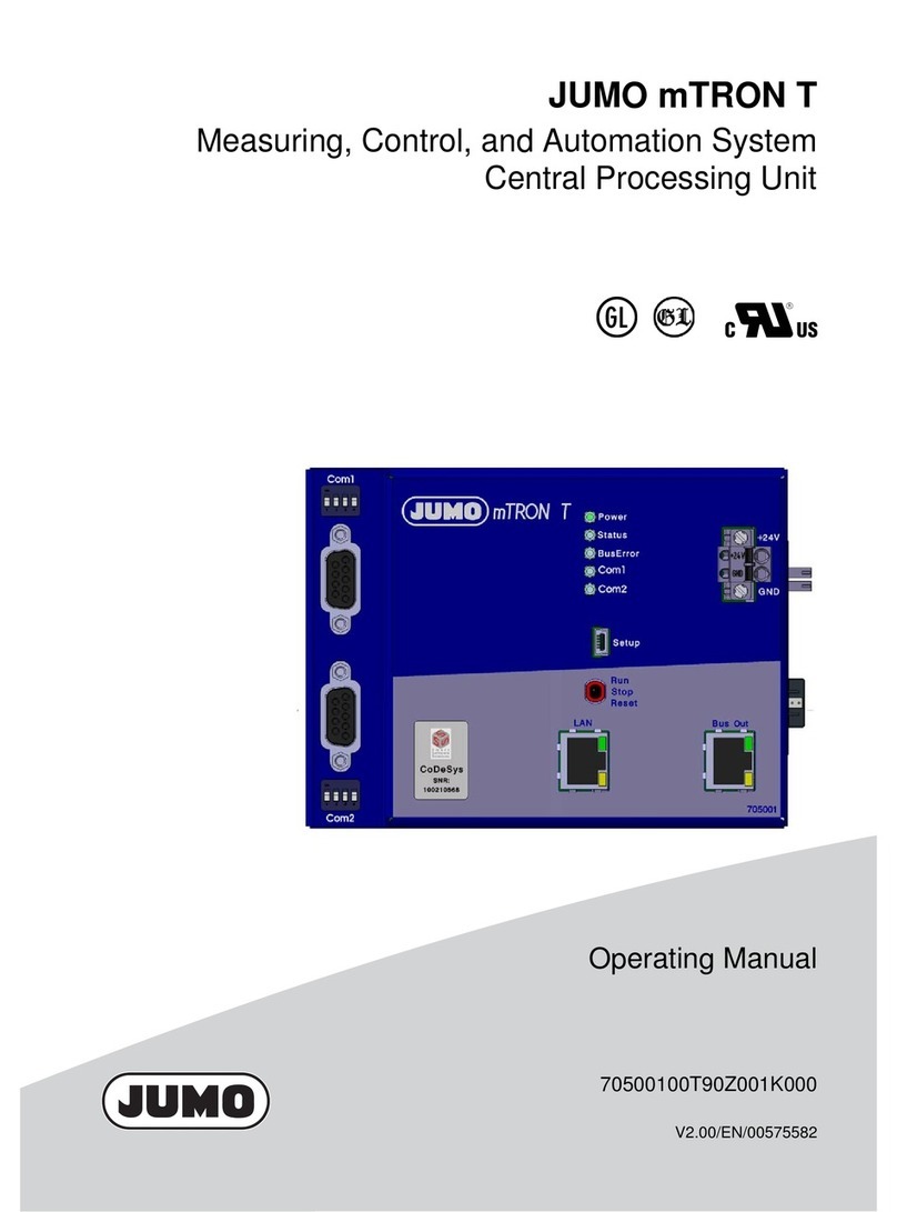
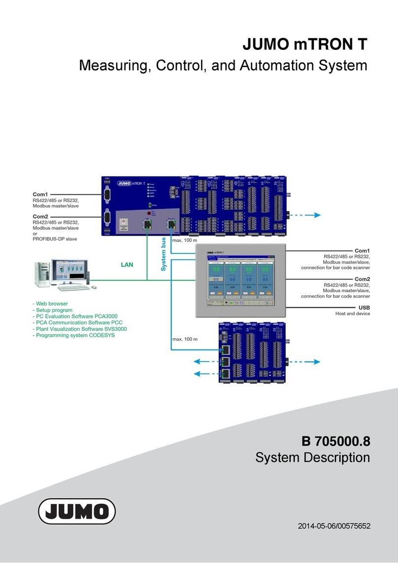
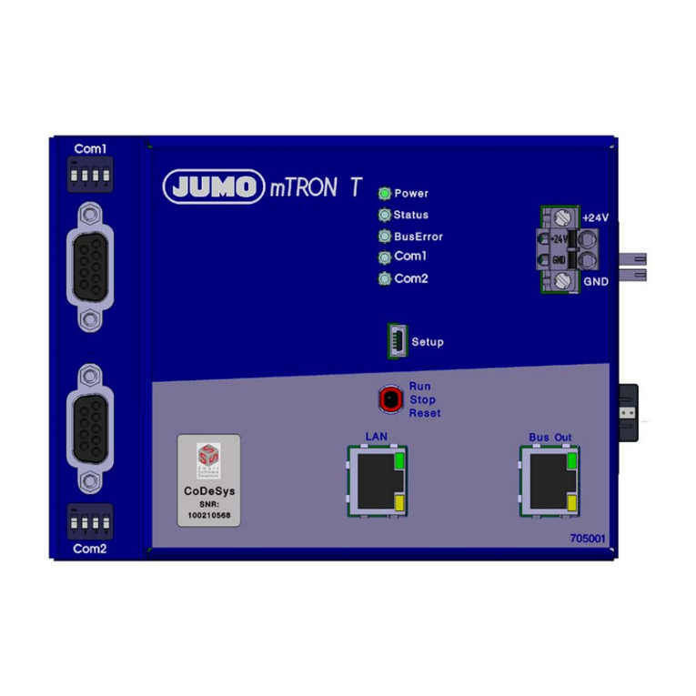
JUMO variTRON 300 User manual

70500300T90Z001K000
V5.00/EN/00748411/2022-06-07
JUMO variTRON 300
Automation System
Central Processing Unit 705003
Operating Manual


Contents
Contents
1 Introduction . . . . . . . . . . . . . . . . . . . . . . . . . . . . . . . . . . . . . . . . . . . . . . . . . 7
1.1 Safety information . . . . . . . . . . . . . . . . . . . . . . . . . . . . . . . . . . . . . . . . . . . . . . . . . . . . . . . . .7
1.2 Trademark information . . . . . . . . . . . . . . . . . . . . . . . . . . . . . . . . . . . . . . . . . . . . . . . . . . . . .8
1.3 Intended use . . . . . . . . . . . . . . . . . . . . . . . . . . . . . . . . . . . . . . . . . . . . . . . . . . . . . . . . . . . . .8
1.4 Qualification of personnel . . . . . . . . . . . . . . . . . . . . . . . . . . . . . . . . . . . . . . . . . . . . . . . . . . .8
1.5 Acceptance of goods, storage, and transport . . . . . . . . . . . . . . . . . . . . . . . . . . . . . . . . . . . .9
1.5.1 Checking the delivery . . . . . . . . . . . . . . . . . . . . . . . . . . . . . . . . . . . . . . . . . . . . . . . . . . . . . .9
1.5.2 Important information about storage and transport. . . . . . . . . . . . . . . . . . . . . . . . . . . . . . . .9
1.5.3 Returning goods . . . . . . . . . . . . . . . . . . . . . . . . . . . . . . . . . . . . . . . . . . . . . . . . . . . . . . . . . .9
1.5.4 Disposal . . . . . . . . . . . . . . . . . . . . . . . . . . . . . . . . . . . . . . . . . . . . . . . . . . . . . . . . . . . . . . . .10
1.6 Identifying the device version . . . . . . . . . . . . . . . . . . . . . . . . . . . . . . . . . . . . . . . . . . . . . . . .11
1.6.1 Nameplate. . . . . . . . . . . . . . . . . . . . . . . . . . . . . . . . . . . . . . . . . . . . . . . . . . . . . . . . . . . . . . .11
1.6.2 Order details . . . . . . . . . . . . . . . . . . . . . . . . . . . . . . . . . . . . . . . . . . . . . . . . . . . . . . . . . . . . .12
1.6.3 Scope of delivery . . . . . . . . . . . . . . . . . . . . . . . . . . . . . . . . . . . . . . . . . . . . . . . . . . . . . . . . .13
1.6.4 Accessories. . . . . . . . . . . . . . . . . . . . . . . . . . . . . . . . . . . . . . . . . . . . . . . . . . . . . . . . . . . . . .13
1.7 Module overview . . . . . . . . . . . . . . . . . . . . . . . . . . . . . . . . . . . . . . . . . . . . . . . . . . . . . . . . . .14
1.7.1 Central processing unit . . . . . . . . . . . . . . . . . . . . . . . . . . . . . . . . . . . . . . . . . . . . . . . . . . . . .14
1.7.2 Modules . . . . . . . . . . . . . . . . . . . . . . . . . . . . . . . . . . . . . . . . . . . . . . . . . . . . . . . . . . . . . . . .15
1.8 Available technical documentation . . . . . . . . . . . . . . . . . . . . . . . . . . . . . . . . . . . . . . . . . . . .18
1.8.1 Central processing unit . . . . . . . . . . . . . . . . . . . . . . . . . . . . . . . . . . . . . . . . . . . . . . . . . . . . .18
1.8.2 Input/output modules . . . . . . . . . . . . . . . . . . . . . . . . . . . . . . . . . . . . . . . . . . . . . . . . . . . . . .18
1.8.3 Special modules . . . . . . . . . . . . . . . . . . . . . . . . . . . . . . . . . . . . . . . . . . . . . . . . . . . . . . . . . .19
1.8.4 Panels . . . . . . . . . . . . . . . . . . . . . . . . . . . . . . . . . . . . . . . . . . . . . . . . . . . . . . . . . . . . . . . . . .19
1.8.5 Power supply units . . . . . . . . . . . . . . . . . . . . . . . . . . . . . . . . . . . . . . . . . . . . . . . . . . . . . . . .19
1.9 System version . . . . . . . . . . . . . . . . . . . . . . . . . . . . . . . . . . . . . . . . . . . . . . . . . . . . . . . . . . .19
2 Mounting . . . . . . . . . . . . . . . . . . . . . . . . . . . . . . . . . . . . . . . . . . . . . . . . . . . 21
2.1 General information on installation/dismounting . . . . . . . . . . . . . . . . . . . . . . . . . . . . . . . . . .21
2.2 Installation/dismounting on DIN rail . . . . . . . . . . . . . . . . . . . . . . . . . . . . . . . . . . . . . . . . . . .22
2.2.1 Central processing unit . . . . . . . . . . . . . . . . . . . . . . . . . . . . . . . . . . . . . . . . . . . . . . . . . . . . .23
2.3 Dimensions . . . . . . . . . . . . . . . . . . . . . . . . . . . . . . . . . . . . . . . . . . . . . . . . . . . . . . . . . . . . . .25
3 Electrical connection . . . . . . . . . . . . . . . . . . . . . . . . . . . . . . . . . . . . . . . . . 27
3.1 Installation notes . . . . . . . . . . . . . . . . . . . . . . . . . . . . . . . . . . . . . . . . . . . . . . . . . . . . . . . . . .27
3.2 Galvanic isolation . . . . . . . . . . . . . . . . . . . . . . . . . . . . . . . . . . . . . . . . . . . . . . . . . . . . . . . . .28
3.3 Connection diagram . . . . . . . . . . . . . . . . . . . . . . . . . . . . . . . . . . . . . . . . . . . . . . . . . . . . . . .28
3.3.1 Display, operating, and connection elements . . . . . . . . . . . . . . . . . . . . . . . . . . . . . . . . . . . .28
3.3.2 Interfaces . . . . . . . . . . . . . . . . . . . . . . . . . . . . . . . . . . . . . . . . . . . . . . . . . . . . . . . . . . . . . . .29
3.3.3 Voltage supply. . . . . . . . . . . . . . . . . . . . . . . . . . . . . . . . . . . . . . . . . . . . . . . . . . . . . . . . . . . .30
3.3.4 Terminating resistors. . . . . . . . . . . . . . . . . . . . . . . . . . . . . . . . . . . . . . . . . . . . . . . . . . . . . . .30

Contents
4 Operation . . . . . . . . . . . . . . . . . . . . . . . . . . . . . . . . . . . . . . . . . . . . . . . . . . . 31
4.1 General information . . . . . . . . . . . . . . . . . . . . . . . . . . . . . . . . . . . . . . . . . . . . . . . . . . . . . . .31
4.2 Device . . . . . . . . . . . . . . . . . . . . . . . . . . . . . . . . . . . . . . . . . . . . . . . . . . . . . . . . . . . . . . . . . .32
4.2.1 Display and control elements . . . . . . . . . . . . . . . . . . . . . . . . . . . . . . . . . . . . . . . . . . . . . . . .32
4.2.2 Device menu . . . . . . . . . . . . . . . . . . . . . . . . . . . . . . . . . . . . . . . . . . . . . . . . . . . . . . . . . . . . .33
4.2.3 User log-on . . . . . . . . . . . . . . . . . . . . . . . . . . . . . . . . . . . . . . . . . . . . . . . . . . . . . . . . . . . . . .35
4.2.4 Reset to factory settings . . . . . . . . . . . . . . . . . . . . . . . . . . . . . . . . . . . . . . . . . . . . . . . . . . . .36
4.3 Setup program . . . . . . . . . . . . . . . . . . . . . . . . . . . . . . . . . . . . . . . . . . . . . . . . . . . . . . . . . . .37
4.3.1 Start page . . . . . . . . . . . . . . . . . . . . . . . . . . . . . . . . . . . . . . . . . . . . . . . . . . . . . . . . . . . . . . .37
4.3.2 Project map. . . . . . . . . . . . . . . . . . . . . . . . . . . . . . . . . . . . . . . . . . . . . . . . . . . . . . . . . . . . . .38
4.3.3 Project management. . . . . . . . . . . . . . . . . . . . . . . . . . . . . . . . . . . . . . . . . . . . . . . . . . . . . . .39
4.3.4 System bus HW assistant . . . . . . . . . . . . . . . . . . . . . . . . . . . . . . . . . . . . . . . . . . . . . . . . . . .40
4.3.5 Optional module (alias device address) . . . . . . . . . . . . . . . . . . . . . . . . . . . . . . . . . . . . . . . .42
4.3.6 Wtrans HW assistant . . . . . . . . . . . . . . . . . . . . . . . . . . . . . . . . . . . . . . . . . . . . . . . . . . . . . .44
4.3.7 Configuration. . . . . . . . . . . . . . . . . . . . . . . . . . . . . . . . . . . . . . . . . . . . . . . . . . . . . . . . . . . . .46
4.3.8 PLC application. . . . . . . . . . . . . . . . . . . . . . . . . . . . . . . . . . . . . . . . . . . . . . . . . . . . . . . . . . .48
4.3.9 PLC parameter definition . . . . . . . . . . . . . . . . . . . . . . . . . . . . . . . . . . . . . . . . . . . . . . . . . . .49
4.3.10 Languages . . . . . . . . . . . . . . . . . . . . . . . . . . . . . . . . . . . . . . . . . . . . . . . . . . . . . . . . . . . . . .50
4.3.11 Data transfer . . . . . . . . . . . . . . . . . . . . . . . . . . . . . . . . . . . . . . . . . . . . . . . . . . . . . . . . . . . . .52
4.3.12 Messages . . . . . . . . . . . . . . . . . . . . . . . . . . . . . . . . . . . . . . . . . . . . . . . . . . . . . . . . . . . . . . .55
4.3.13 Connections . . . . . . . . . . . . . . . . . . . . . . . . . . . . . . . . . . . . . . . . . . . . . . . . . . . . . . . . . . . . .56
4.4 JUMO Web Cockpit . . . . . . . . . . . . . . . . . . . . . . . . . . . . . . . . . . . . . . . . . . . . . . . . . . . . . . .58
4.4.1 Device information . . . . . . . . . . . . . . . . . . . . . . . . . . . . . . . . . . . . . . . . . . . . . . . . . . . . . . . .61
4.4.2 Events . . . . . . . . . . . . . . . . . . . . . . . . . . . . . . . . . . . . . . . . . . . . . . . . . . . . . . . . . . . . . . . . . .62
4.4.3 Alarms. . . . . . . . . . . . . . . . . . . . . . . . . . . . . . . . . . . . . . . . . . . . . . . . . . . . . . . . . . . . . . . . . .62
4.4.4 Configuration. . . . . . . . . . . . . . . . . . . . . . . . . . . . . . . . . . . . . . . . . . . . . . . . . . . . . . . . . . . . .63
4.4.5 Service . . . . . . . . . . . . . . . . . . . . . . . . . . . . . . . . . . . . . . . . . . . . . . . . . . . . . . . . . . . . . . . . .65
4.4.6 File explorer . . . . . . . . . . . . . . . . . . . . . . . . . . . . . . . . . . . . . . . . . . . . . . . . . . . . . . . . . . . . .67
5 Configuration. . . . . . . . . . . . . . . . . . . . . . . . . . . . . . . . . . . . . . . . . . . . . . . . 69
5.1 General information . . . . . . . . . . . . . . . . . . . . . . . . . . . . . . . . . . . . . . . . . . . . . . . . . . . . . . .69
5.2 Device manager . . . . . . . . . . . . . . . . . . . . . . . . . . . . . . . . . . . . . . . . . . . . . . . . . . . . . . . . . .70
5.2.1 Customer-specific linearization . . . . . . . . . . . . . . . . . . . . . . . . . . . . . . . . . . . . . . . . . . . . . . .71
5.3 System bus . . . . . . . . . . . . . . . . . . . . . . . . . . . . . . . . . . . . . . . . . . . . . . . . . . . . . . . . . . . . . .73
5.4 Data carrier management . . . . . . . . . . . . . . . . . . . . . . . . . . . . . . . . . . . . . . . . . . . . . . . . . . .74
5.5 Ethernet . . . . . . . . . . . . . . . . . . . . . . . . . . . . . . . . . . . . . . . . . . . . . . . . . . . . . . . . . . . . . . . .75
5.6 Web server . . . . . . . . . . . . . . . . . . . . . . . . . . . . . . . . . . . . . . . . . . . . . . . . . . . . . . . . . . . . . .75
5.7 Email . . . . . . . . . . . . . . . . . . . . . . . . . . . . . . . . . . . . . . . . . . . . . . . . . . . . . . . . . . . . . . . . . . .76
5.8 PLC configuration . . . . . . . . . . . . . . . . . . . . . . . . . . . . . . . . . . . . . . . . . . . . . . . . . . . . . . . . .77
5.8.1 Units . . . . . . . . . . . . . . . . . . . . . . . . . . . . . . . . . . . . . . . . . . . . . . . . . . . . . . . . . . . . . . . . . . .77
5.8.2 Program generator . . . . . . . . . . . . . . . . . . . . . . . . . . . . . . . . . . . . . . . . . . . . . . . . . . . . . . . .77
5.8.3 Analog variables . . . . . . . . . . . . . . . . . . . . . . . . . . . . . . . . . . . . . . . . . . . . . . . . . . . . . . . . . .81
5.8.4 Digital variables. . . . . . . . . . . . . . . . . . . . . . . . . . . . . . . . . . . . . . . . . . . . . . . . . . . . . . . . . . .81

Contents
5.9 PLC parameters . . . . . . . . . . . . . . . . . . . . . . . . . . . . . . . . . . . . . . . . . . . . . . . . . . . . . . . . . .81
5.10 Programs . . . . . . . . . . . . . . . . . . . . . . . . . . . . . . . . . . . . . . . . . . . . . . . . . . . . . . . . . . . . . . .82
5.11 System status UI. . . . . . . . . . . . . . . . . . . . . . . . . . . . . . . . . . . . . . . . . . . . . . . . . . . . . . . . . .84
5.12 Real-time processing . . . . . . . . . . . . . . . . . . . . . . . . . . . . . . . . . . . . . . . . . . . . . . . . . . . . . .85
5.12.1 Data recording . . . . . . . . . . . . . . . . . . . . . . . . . . . . . . . . . . . . . . . . . . . . . . . . . . . . . . . . . . .85
5.13 Datastore gateway . . . . . . . . . . . . . . . . . . . . . . . . . . . . . . . . . . . . . . . . . . . . . . . . . . . . . . . .88
5.14 Cloud gateway . . . . . . . . . . . . . . . . . . . . . . . . . . . . . . . . . . . . . . . . . . . . . . . . . . . . . . . . . . .89
5.15 Wtrans gateway . . . . . . . . . . . . . . . . . . . . . . . . . . . . . . . . . . . . . . . . . . . . . . . . . . . . . . . . . .90
5.16 Node-RED. . . . . . . . . . . . . . . . . . . . . . . . . . . . . . . . . . . . . . . . . . . . . . . . . . . . . . . . . . . . . . .91
5.17 Batches . . . . . . . . . . . . . . . . . . . . . . . . . . . . . . . . . . . . . . . . . . . . . . . . . . . . . . . . . . . . . . . . .92
6 Startup . . . . . . . . . . . . . . . . . . . . . . . . . . . . . . . . . . . . . . . . . . . . . . . . . . . . . 95
7 Annex . . . . . . . . . . . . . . . . . . . . . . . . . . . . . . . . . . . . . . . . . . . . . . . . . . . . . . 99
7.1 Technical data . . . . . . . . . . . . . . . . . . . . . . . . . . . . . . . . . . . . . . . . . . . . . . . . . . . . . . . . . . . .99
7.1.1 Interfaces . . . . . . . . . . . . . . . . . . . . . . . . . . . . . . . . . . . . . . . . . . . . . . . . . . . . . . . . . . . . . . .99
7.1.2 Display . . . . . . . . . . . . . . . . . . . . . . . . . . . . . . . . . . . . . . . . . . . . . . . . . . . . . . . . . . . . . . . . .101
7.1.3 Electrical data . . . . . . . . . . . . . . . . . . . . . . . . . . . . . . . . . . . . . . . . . . . . . . . . . . . . . . . . . . . .101
7.1.4 Housing and environmental conditions . . . . . . . . . . . . . . . . . . . . . . . . . . . . . . . . . . . . . . . . .102
7.1.5 Approvals and approval marks . . . . . . . . . . . . . . . . . . . . . . . . . . . . . . . . . . . . . . . . . . . . . . .102
7.2 Buffer battery replacement . . . . . . . . . . . . . . . . . . . . . . . . . . . . . . . . . . . . . . . . . . . . . . . . . .103
7.3 LED displays . . . . . . . . . . . . . . . . . . . . . . . . . . . . . . . . . . . . . . . . . . . . . . . . . . . . . . . . . . . . .106
7.4 Open-source software. . . . . . . . . . . . . . . . . . . . . . . . . . . . . . . . . . . . . . . . . . . . . . . . . . . . . .108
7.4.1 Information on open-source software . . . . . . . . . . . . . . . . . . . . . . . . . . . . . . . . . . . . . . . . . .108
7.5 China RoHS . . . . . . . . . . . . . . . . . . . . . . . . . . . . . . . . . . . . . . . . . . . . . . . . . . . . . . . . . . . . .109

Contents

7
1 Introduction
1 Introduction
1.1 Safety information
General
This manual contains information that must be observed in the interest of your own safety and to avoid
material damage. This information is supported by symbols which are used in this manual as indicated.
Please read this manual before starting up the device. Store this manual in a place that is accessible to
all users at all times.
If difficulties occur during startup, please do not intervene in any way that could jeopardize your warranty
rights!
Warning symbols
WARNING!
This symbol in connection with the signal word indicates that personal injury may occur if the respective
precautionary measures are not carried out.
CAUTION!
This symbol in connection with the signal word indicates that material damage or data loss will occur
if the respective precautionary measures are not taken.
CAUTION!
This symbol indicates that components could be destroyed by electrostatic discharge (ESD = Electro
Static Discharge) if the respective cautionary measures are not taken.
Only use the ESD packages intended for this purpose to return device inserts, assembly groups, or as-
sembly components.
Note symbols
NOTE!
This symbol refers to important information about the product, its handling, or additional benefits.
READ THE DOCUMENTATION!
This symbol, which is attached to the device, indicates that the associated documentation for the de-
vice must be observed. This is necessary to identify the nature of the potential hazard, and to take
measures to prevent it.
REFERENCE!
This symbol refers to additional information in other sections, chapters, or other manuals.
FURTHER INFORMATION!
This symbol is used in tables and indicates that further information is provided after the table.
&
DISPOSAL!
At the end of its service life, the device and any batteries present do not belong in the trash! Please en-
sure that they are disposed of properly and in an environmentally friendly manner.

1 Introduction
8
1.2 Trademark information
• Microsoft® is a registered trademark of Microsoft Corp., Redmond, VA 98052-6399, US.
• Windows® is a registered trademark of Microsoft Corp., Redmond, VA 98052-6399, US.
• Microsoft Edge® is a registered trademark of Microsoft Corp., Redmond, VA 98052-6399, US.
• Google Chrome® is a registered trademark of Google LLC, 94043, Mountain View, US.
• Opera® is a registered trademark of Opera Software AS, 0484, Oslo, NO.
• Mozilla® is a registered trademark of Mozilla Foundation, 94041, Mountain View, US.
• Firefox® is a registered trademark of Mozilla Foundation, 94041, Mountain View, US.
1.3 Intended use
The device is designed for use in an industrial environment as specified in the technical data. Other uses
beyond those defined are not viewed as intended uses.
The device has been manufactured in compliance with applicable standards and directives as well as
the applicable safety regulations. Nevertheless, improper use may lead to personal injury or material
damage.
To avoid danger, only use the device:
• For the intended use
• When in good order and condition
• When taking the technical documentation provided into account
Risks resulting from the application may arise, e.g. as the result of missing safety provisions or wrong
settings, even when the device is used properly and as intended.
1.4 Qualification of personnel
This document contains the necessary information for the intended use of the device to which it relates.
It is intended for staff with technical qualifications who have been specially trained and have the appro-
priate knowledge in the field of automation technology.
The appropriate level of knowledge and the technically fault-free implementation of the safety informa-
tion and warnings contained in the technical documentation provided are prerequisites for risk-free
mounting, installation, and startup as well as for ensuring safety when operating the described modules.
Only qualified personnel have the required specialist knowledge to correctly interpret and implement the
safety information and warnings contained in this document in specific situations.

9
1 Introduction
1.5 Acceptance of goods, storage, and transport
1.5.1 Checking the delivery
• Ensure that the packaging and its contents are undamaged.
• Check the delivery for completeness against the packing slip and order details.
• Inform the supplier immediately if there is any damage.
• Store damaged parts until clarification is received from the supplier.
1.5.2 Important information about storage and transport
• Store the device in a dry, clean environment. Observe the admissible ambient conditions (see "Tech-
nical data")
• Protect the device from shock during transport
• The original packaging provides optimum protection for storage and transport
1.5.3 Returning goods
If repairs are needed, return the complete device in clean condition.
Use the original packaging to return goods.
Accompanying letter for repair
Please include the completed accompanying letter for repair when returning goods.
Do not forget to state the following:
• Description of the application and
• Description of the error that has occurred
The accompanying letter for repair (supplementary sheet for product returns) can be downloaded online
from the manufacturer's website:
http://productreturn.jumo.info
Protection against electrostatic discharge (ESD)
(ESD = electrostatic discharge)
To prevent damage due to ESD, electronic modules or components must be handled, packaged, and
stored in an ESD-protected environment. Measures that protect against electrostatic discharge and elec-
tric fields are described in DIN EN 61340-5-1 and DIN EN 61340-5-2 "Protection of electronic devices
from electrostatic phenomena".
When sending back electronic modules or components, please note the following:
• Pack sensitive components only in an environment providing protection against ESD. Workspaces
such as this divert electrostatic charges to ground in a controlled manner and prevent static charges
due to friction.
• Use only packaging intended specifically for ESD-sensitive modules/components. These must con-
sist of conductive plastics.
No liability can be assumed for damage caused by ESD.
CAUTION!
Electrostatic charges occur in non-ESD-protected environments.
Electrostatic discharges can damage modules or components.
For transport purposes, use only the ESD packaging provided.

1 Introduction
10
1.5.4 Disposal
Disposing of the packaging material
The entire packaging material (cardboard packaging, inserts, plastic film, and plastic bags) is fully recy-
clable.
The country-specific laws and regulations for waste treatment and disposal must be observed.
Disposing of the device
DISPOSAL!
Devices and/or replaced parts (including batteries) should not be placed in the refuse bin at the end of
their service life, but must be disposed of properly and in an environmentally friendly manner.
The device consists of materials that can be recycled by specialist recycling plants.
The country-specific laws and regulations for waste treatment and disposal must be observed.

11
1 Introduction
1.6 Identifying the device version
1.6.1 Nameplate
Position
The nameplate (A) is affixed to the module case.
Table of contents
The nameplate contains important information. This includes:
Device type (Typ)
Compare the specifications on the nameplate with the order.
Identify the supplied device version using the order details (order code).
Part no. (TN)
The part no. uniquely identifies an article in the catalog. It is important for communication between the
customer and the sales department.
Fabrication number (F-Nr.)
The fabrication number indicates, among other things, the date of manufacture (year/week).
Example: F-Nr = 0070033801220500006
The characters in question are digits 12, 13, 14, and 15 (from the left).
The device was therefore produced in the 50th week of 2020.
(A)
Description Designation on the
nameplate
Example
Device type Type 705003/01008-00-36/000.224
Part no. TN 00123456
Fabrication number F-Nr. 0070033801220500006
Voltage supply - DC 24 V, +25/-20 %

1 Introduction
12
1.6.2 Order details
(1) Basic type
705003 Central processing unit, type 705003 (2 × Ethernet (RJ45), 1 × USB host interface,
1 × RS485 interface), Node-RED)
(2) Basic type extension 1
0Single core CPU
(3) Basic type extension 2
1 RAM 512 MB
(4) Basic type extension 3
1 eMMC 2 GBa
aFlexible allocation between system data and application data.
(5) Basic type extension 4
0 Without software control loops
(6) Version
8 Standard with default settings
(7) Wireless interface
00 Without interface
10 Wtrans 868.4 MHz (Europe)
20 Wtrans 915 MHz (America, Australia, Canada and New Zealand)
(8) Voltage supply
36 DC 24 V +25/-20 %, SELV
(9) DNV GL approved
000 Without approval
(10) Extra codesb
bThe central processing unit can be extended with various functions through extra codes. For perfor-
mance reasons, it may not be possible to use all functions (extra codes) simultaneously, depending
on the application. As a more powerful device, the JUMO variTRON 500 central processing unit (type
705002) is available. Your contact person in Technical Sales will be happy to advise you on selecting
the appropriate central processing unit for your application.
224 PLC according to IEC 61131-3 (CODESYS V3.5; necessary to operate the device as
a PLC)c
cThis function can be used in demo mode free of charge for 30 minutes.
225 Program generator 1 – 9d
dOnly in conjunction with extra code 224.
280 Remote TargetVisuc, d
281 WebVisuc, d
282 PROFINET IO controllerc, d
283 OPC UA serverc, d, e
eNot available with system version 6.
284 Modbus TCP masterc, d
285 Modbus TCP slavec, d
286 EtherCAT masterc, d
289 BACnet/IPc, d

13
1 Introduction
1.6.3 Scope of delivery
1.6.4 Accessories
(1) (2) (3) (4) (5) (6) (7) (8) (9) (10)
Order
code
705003 / 0 1 1 0 - 8 - - 36 / 000 , 224 , ...a
aList further extra codes in sequence, separated by commas.
Order ex-
ample
705003 / 0 1 1 0 - 8 - 00 - 36 / 000 , 224
1 central processing unit, type 705003, in the ordered version
1 lambda/4-antenna (only for device with wireless interface)
1 installation instructions
Designation Part no.
RJ45 patch cable SF/UTP, length 0.3 m 00747472
Antenna cable, length 1 m, impedance 50 ohm with preconfigured screw-type connec-
tion, Tmax. 85 °C
00710813
Antenna cable, length 3 m, impedance 50 ohm with preconfigured screw-type connec-
tion, Tmax. 85 °C
00482646
Antenna cable, length 5 m, impedance 50 ohm with preconfigured screw-type connec-
tion, Tmax. 85 °C
00490066
Antenna cable, length 5 m, impedance 50 ohm with preconfigured screw-type connec-
tion, Tmax. 125 °C
00660378
Antenna cable, length 10 m, impedance 50 ohm with preconfigured screw-type con-
nection, Tmax. 85 °C
00490068
Antenna cable, length 10 m, impedance 50 ohm with preconfigured screw-type con-
nection, Tmax. 125 °C
00511870
Antenna holder for wall mounting with antipole for lambda/4-antenna 00482648
Lambda/4-antenna with waterproof line permanently connected, length 10 m,
Tmax. 125 °C
00757047
Additional lambda/4-antenna, impedance 50 ohm, Tmax. 125 °C 00757039

1 Introduction
14
1.7 Module overview
1.7.1 Central processing unit
The central processing unit JUMO variTRON 300 along with the proven input and output modules (incl.
controller module) as well as the router modules (primarily router module 1-port, 705043) form a com-
plete system.
The central processing unit manages all configuration and parameter data of the complete system and
makes a PLC acc. to IEC 61131-3 (CODESYS V3.5) available (extra code). The PLC can be activated
in different versions:
• CODESYS runtime system
• CODESYS runtime system incl. Remote TargetVisu
• CODESYS runtime system incl. WebVisu
• CODESYS runtime system incl. Remote TargetVisu and WebVisu
For visualization, commercially available panels are used which support CODESYS Remote TargetVisu
or WebVisu functionality. The visualization is also possible via web browser. Visualizations have to be
implemented with CODESYS resources (see order details).
A convenient setup program is used for configuration. JUMO standard functions for CODESYS are pro-
vided in libraries (as of system version 6) and can be individually integrated into the customer applica-
tion.
As of system version 5, the central processing unit JUMO variTRON 300 is also optionally usable as a
receiver for the JUMO Wtrans transmitters, thereby enabling wireless transmission of measured values.
Module designation Data sheet Features
JUMO variTRON 300
Central processing unit
705003 • Process mapping for all connected input/out-
put modules (incl. controller modules)
• Display and keys to display the system status
• USB host interface
• OPC UA server (in conjunction with PLC)
• 9 program generators (in conjunction with
PLC)
• Field bus interface (RS485; Modbus RTU in
conjunction with PLC)
• PROFINET IO controller (in conjunction with
PLC)
• Plug and Play for input/output module replace-
ment
• Battery-buffered RAM
• Real-time clock

15
1 Introduction
1.7.2 Modules
The proven input and output modules are available as module variants (type 7050xx; incl. controller
module).
For example: the analog input module with universal inputs for thermocouples, RTD temperature probes,
and voltage or current standard signals. As a result the same hardware can be used to precisely acquire
and digitize a highly diverse range of process variables.
JUMO variTRON 300 enables simultaneous operation of up to 32 control loops so that it can also be
used for sophisticated processes. Through expansion slots the inputs and outputs of each controller
module can be individually expanded and adapted. The control loops here operate fully independently,
which means they do not require resources from the central processing unit.
Thyristor power controllers can also be connected via EtherCAT or PROFINET. In addition, JUMO dig-
iLine sensors for liquid analysis can be connected to the central processing unit.
Wireless transmission of measured values
As of system version 5, the central processing unit JUMO variTRON 300 is also available with a wireless
interface that enables wireless transmission of measured values. The transmitters of the JUMO Wtrans
series are available as measuring probes (Wtrans T, Wtrans B, Wtrans p). A maximum of 32 transmitters
can be operated on the central processing unit.
During startup, the display of the RSSI value (Received Signal Strength Indicator) in the Web Cockpit is
helpful as an indicator of the signal strength of a received radio telegram.
Input/output modules
Module designation Data sheet Features
Multichannel controller module 705010 • Up to 4 independently configurable PID control
loops with a fast cycle time and proven control
algorithms
• Independent operation
• Math and logic functions
• Counter input up to 10 kHz
Relay module 4-channel 705015 • 4 relay outputs controlled via the system bus
by digital signals
• Changeover contact in each case (230 V / 3 A)
• Switching statuses are displayed with LEDs
Analog input module
4-channel
705020 • 4 high-quality, configurable analog inputs for
RTD temperature probes, resistance transmit-
ters, thermocouples, current 0(4) to 20 mA,
voltage 0(2) to 10 V
• All inputs are galvanically isolated from each
other
• Customer-specific linearization possible
• Limit value monitoring
• Additional digital input
Analog input module
8-channel
705021 • 8 high-quality analog inputs for RTD tempera-
ture probes Pt100, Pt500, Pt1000 in two-wire
circuit
• Limit value monitoring
• Additional digital input
Analog output module
4-channel
705025 • 4 configurable analog outputs 0(4) to 20 mA or
0(2) to 10 V
• Adjustable output behavior in case of malfunc-
tion

1 Introduction
16
Special modules
Panels
Power supply units
Digital input/output module
12-channel
705030 • 12 digital inputs or outputs
• Each channel can be individually configured as
an input DC 0/24 V or ouput DC 24 V
• Load capacity per output: 500 mA
• Switching states are visualized by LED
Digital input/output module
32-channel
(as of system version 3)
705031 • 17 digital outputs
• up to 15 additional digital inputs or outputs
• Load capacity per output: 500 mA
• Switching states are visualized by LED
Thyristor power controller
Type 70906x
(as of system version 3)
709061, 709062,
709063
• For one-phase and three-phase operation
• Continuous load current up to 250 A, load volt-
age up to 500 V
• Different circuit variants, load types and oper-
ating modes can be realized
Module designation Data sheet Features
Router module 2-port
(as of system version 3)
705041 • Mounting behind another module (or the CPU)
on DIN rail (side system bus input and output)
• Is used exclusively for system bus expansion
via RJ45 sockets on the front (2 x Bus Out)
Router module 3-port
(as of system version 3)
705042 • Use as first module on an additional DIN rail to
connect further modules (system bus input via
RJ45 socket; system bus output on the side)
• Is used additionally for system bus expansion
or increasing the system bus range, via RJ45
sockets on the front (1 x Bus In, 2 x Bus Out)
Router module 1-port
(as of system version 4)
705043 • Use together with a central processing unit
variTRON 300 to connect the modules (sys-
tem bus input via RJ45 socket; system bus
output on the side)
• Is used additionally for system bus expansion
Module designation Data sheet Features
JUMO variTRON Web panels 705070 • Versions for different requirements (e.g. stan-
dard, Foot & Beverage)
• Screen diagonals from 10.9 cm (4.3″) to
54.6 cm (21.5″)
• TFT- touchscreen, capacitive or resistive
Module designation Data sheet Features
Power supply unit
705090/03-33
705090 • AC 100 to 240 V wide-range input
• Output: DC 24 V / 3.4 A
Power supply unit
705090/05-33
705090 • AC 100 to 240 V wide-range input
• Output: DC 24 V / 5 A

17
1 Introduction
Power supply unit
705090/10-33
705090 • AC 100 to 240 V wide-range input
• Output: DC 24 V / 10 A
Module designation Data sheet Features

1 Introduction
18
1.8 Available technical documentation
The documentation for the automation system is addressed to plant manufacturers and users with spe-
cialist training and consists of the following documents (previous document number in brackets).
1.8.1 Central processing unit
1.8.2 Input/output modules
Product Document No. Printed PDF file
variTRON 300
Central processing
unit
Data sheet 70500300T10... - X
Operating manual 70500300T90... - X
Installation instructions 70500300T94... X X
Product Document No. Printed PDF file
Multichannel
controller module
Data sheet 70501000T10... - X
Operating manual 70501000T90...
(B 705010.0)
-X
Installation instructions 70501000T94...
(B 705010.4)
XX
Relay module
4-channel
Data sheet 70501500T10... - X
Operating manual 70501500T90...
(B 705015.0)
-X
Installation instructions 70501500T94...
(B 705015.4)
XX
Analog input
module
4-channel
Data sheet 70502000T10... - X
Operating manual 70502000T90...
(B 705020.0)
-X
Installation instructions 70502000T94...
(B 705020.4)
XX
Analog input
module
8-channel
Data sheet 70502100T10... - X
Operating manual 70502100T90...
(B 705021.0)
-X
Installation instructions 70502100T94...
(B 705021.4)
XX
Analog output
module
4-channel
Data sheet 70502500T10... - X
Operating manual 70502500T90... - X
Installation instructions 70502500T94... X X
Digital input/output
module
12-channel
Data sheet 70503000T10... - X
Operating manual 70503000T90...
(B 705030.0)
-X
Installation instructions 70503000T94...
(B 705030.4)
XX
Digital input/output
module
32-channel
(as of system
version 3)
Data sheet 70503100T10... - X
Operating manual 70503100T90... - X
Installation instructions 70503100T94... X X

19
1 Introduction
1.8.3 Special modules
1.8.4 Panels
1.8.5 Power supply units
1.9 System version
The system version of the automation system is determined by the software version of the central pro-
cessing unit.
Example composition of a version number for the central processing unit 705003: 431.x.y.z.b
431 = basic number
x = major version (= system version)
y = minor version
z = patch version
b = build number
In this document, functions which depend on the system version are marked accordingly (e.g. "as of sys-
tem version x").
Thyristor power
controller
type 70906x
(as of system
version 3)
Operating manual
(integration in the automation sys-
tem)
70500153T90... - X
Product Document No. Printed PDF file
Router module
2-port
(as of system
version 3)
Data sheet 70504100T10... - X
Installation instructions 70504100T94... X X
Router module
3-port
(as of system
version 3)
Data sheet 70504200T10... - X
Installation instructions 70504200T94... X X
Router module
1-port
(as of system
version 4)
Data sheet 70504300T10... - X
Installation instructions 70504300T94... X X
Product Document No. Printed PDF file
JUMO variTRON
Web panels
Data sheet 70507000T10... - X
Product Document No. Printed PDF file
24 V power supply
units
Data sheet 70509000T10... - X
Operating instructions QS3.241 X -
Operating instructions QS5.241 X -
Operating instructions QS10.241 X -

1 Introduction
20
Other manuals for variTRON 300
1
This manual suits for next models
1
Table of contents
Other JUMO Control System manuals