manuals.online logo
Brands
  1. Home
  2. •
  3. Brands
  4. •
  5. Raypak
  6. •
  7. Gas Heater
  8. •
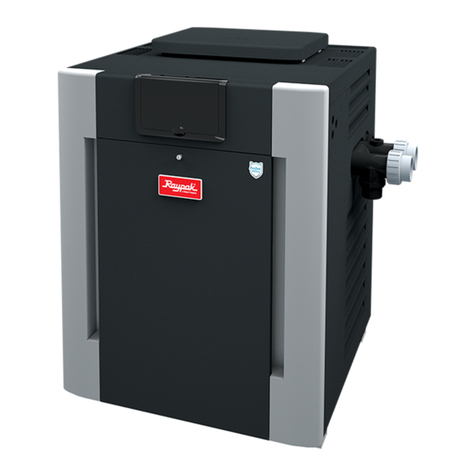
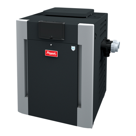
  9. Raypak B-206A-MN-C ASME User manual

Raypak B-206A-MN-C ASME User manual

Digital Gas Heater
Tool Box Quick Reference Guide
Water Chemistry
GENERAL
Recommended Levels Fiberglass Pools Fiberglass Spas Other Pool & Spa Types
Water Temp. (Deg. F) 68 to 88 89 to 104 68 to 104
pH 7.3 to 7.4 7.3 to 7.4 7.6 to 7.8
Total Alkalinity (PPM) 120 to 150 120 to 150 80 to 120
Calcium Hardness (PPM) 200 to 300 150 to 200 200 to 400
Salt (PPM) 4500 MAXIMUM 4500 MAXIMUM 4500 MAXIMUM
Free Chlorine (PPM)22 to 3 2 to 3 2 to 3
Total Dissolved Solids (PPM) 3000 MAXIMUM33000 MAXIMUM33000 MAXIMUM3
For your health and the protection of your pool equipment, it is essential that your water be chemically balanced1.
The following levels must be used as a guide for balanced water.
1 Damage from corrosive water is not covered under warranty. Consult your product manual for more information.
2 Free Chlorine MUST NOT EXCEED 5PPM.
3 In salt water chlorinated pools, the total TDS can be as high as 6000PPM.
• Occasional chemical shock dosing of the pool or spa water should not damage the heater providing the water is
balanced.
• Automaticchemicaldosingdevicesandsaltchlorinatorsareusuallymoreecientinheatedwater,unlesscontrolled,
they can lead to excessive chlorine level which can damage your heater.
• Further advice should be obtained from your pool or spa builder, accredited pool shop, or chemical supplier for the
correct levels for your water.
• Warning: Electrolytic Corrosion and pH instability may be present with salt chlorinated pools.
2
Model Number and Serial Number Location
Before you call Raypak service, make sure you have the MODEL NUMBER and SERIAL NUMBER.
Model & Serial
number can also
be found inside the
control panel above
digital display.
Model & Serial
number located
on rating plate.
Model & Serial number located on
carton label.
GENERAL
3
Minimum Clearances
CLEARANCES
FLOORING: THIS UNIT CAN BE INSTALLED ON COMBUSTIBLE FLOORING. DO NOT INSTALL ON CARPET.
4
INDOOR
View in. (mm)
TOP (above Drafthood) 30 (762)
WATER SIDE 18 (456)
OPPOSITE SIDE 6 (152)
FRONT (Alcove) Open
BACK 6 (152)
FLOOR 0
OUTDOOR
View in. (mm)
TOP (Stackless) 36 (914)
WATER SIDE 18 (456)
OPPOSITE SIDE 6 (152)
BACK 6 (152)
FLOOR 0
See product manual for more information.
Minimum Clearances* – Outdoor
Forced Air Inlet
4' (1.2 m)
Minimum
3' (0.9 m)
Minimum
10' (3 m)
Minimum
1' (0.3 m)
Minimum
4' (1.2 m)
Minimum
4' (1.2 m)
Minimum
DO NOT install near
sprinklers.
DO NOT install within
3 feet of a heat pump
pool heater or air
conditioning
condensing unit.
*Check state and local codes
before proceeding. The
minimum clearances provided
aredenedbyNFGC(National
Fuel Gas Code).
CLEARANCES
5
Minimum Clearances – Indoor
CLEARANCES
VENT CAP
2' MIN (0.6 m)
VENT PIPE
DRAFT HOOD
VENTILATION
AIR OPENING
5' MIN
(1.5 m)
HEATER
2' MIN
(0.6 m)
8' (2.4 m)
OR LESS
COMBUSTION
AIR OPENING
The heater must have both combustion air and
ventilation air.
• Ventilation air opening 12”(305 mm) max from the ceiling
• Combustionairopening12”(305mm)maxfromtheoor
All air from outdoors, each opening shall have a net free
area as shown in table.
Model
Unrestricted
Opening
Sq. In. (m2)
Typical
Screened or
Louvered
opening
Sq. In. (m2)
Typical
Screened and
Louvered
opening
Sq. In. (m2)
206/207 50 (0.03) 75 (0.05) 100 (0.06)
266/267 67 (0.04) 101 (0.06) 134 (0.09)
336/337 84 (0.05) 126 (0.08) 168 (0.11)
406/407 100 (0.06) 150 (0.1) 200 (0.13)
Check state and local codes before proceeding. Some states do not recognize the NFGC and require larger openings.
6
Gas Line Sizing
Maximum Equivalent Pipe Length
Natural Gas 1000 BTU/FT3
0.60SpecicGravity@0.5in.WCPressureDrop
Propane Gas 2500 BTU/FT3
1.53SpecicGravity@0.5in.WCPressureDrop
Model
Input 3/4” 1” 1-1/4” 1-1/2”
(KBTU) N P N P N P N P
206/207 199.5 25 60 90 215 360
266/267 266.0 15 35 50 125 210 480 445
336/337 332.5 10 20 30 80 140 320 290
406/407 399.0 15 20 55 95 225 215 480
GAS SUPPLY
EFFECTS OF LOW GAS PRESSURE
• Pulsatingburnerame
• DelayIgnition/Hardlighto
• Pilot won’t light
• Exposure to condensation
• Emissions not at compliance levels
• Damage to Low NOxburners
7
Gas Pressure Test
Gas Unit
Type
Supply Pressure Manifold
Pressure
Min. Max.
Nat ATM 6” 10.5” 4.0”
Low NOx5” 10.5” 3.1”
Pro ATM 12” 13” 10.5”
GAS SUPPLY
0
1
2
3
4
5
6
1
2
3
4
5
6
TO
BURNER
MANIFOLD
SLACK TUBE
MANOMETER
(INDICATES 8" W.C. AS SHOWN)
MANIFOLD
GAS PRESSURE
INLET GAS PRESSURE
GAS
VALVE
• Supply pressures given are under load
(dynamic)
• 1 PSI = 27.7” Water Column
• Propane requires an external “pounds
to inches regulator”
8
Gas Line Sediment Trap
GAS SUPPLY
Check state and local codes before proceeding. Some states do not recognize the NFGC.
GAS
VALVE
RISER
REDUCER
GAS
COCK
(WITHIN 6 FEET
OF THE HEATER)
CORRECT
PROVIDE CHANGE OF DIRECTION IN GAS FLOW
AS CLOSE AS
PRACTICAL TO HEATER
UNION
GAS
VALVE
RISER
REDUCER
INCORRECT
AS CLOSE AS
PRACTICAL TO HEATER
GAS
COCK
(WITHIN 6 FEET
OF THE HEATER)
UNION
Sediment Trap should be located as close
to the inlet of the appliance as practical.
9
ELECTRICAL
Power Connections
Note: Heater will not work properly if wired to a 208VAC power source.
10
ELECTRICAL
Circuit Board
Printed circuit board. Fully updated and backwards
compatible to all digital heaters manufactured since 2004.
LCD Display is removable
and serviceable.
The LCD P/N is 013640F
11
ELECTRICAL
Circuit Board – Ignition and Temperature Control
Fireman/
Clock
SPR
Vent
Hi Limit
2
Hi Limit
1
PRS
MV
PV
Ground
MV/PV
Roll Out
Switch
24 VAC
Power
Supply
Ground
Common
Hot
Mode
Up
Down
Common
Ground
Ground
Low NO Tab and Fan Wiring
Connection
(Model 207-407 only)
Water
Sensor Program Switch
(re-boot button)
Propane
15 sec.
Tab
Remote
Connections
(Optional)
Propane
90 sec.
tab
Pool
Spa
24V Out
Safety Circuit
Keypad
Gas
Valve
5 Amp 32V
Fast Acting
Automotive
Fuse
P/N 013733F
x
12
13
ELECTRICAL
NOTE: If TAB is NOT broken and the board detects power at
Low NOxconnector, Low NOxTab Fault is displayed and the
heater will not operate.
1a
S
pa
S
et
L
o
104F
T
ab
No
x
F
ault
Low NOx PC Board - Tab Conguration
Connect White/ Violet
wire from “Low NO ”
connector to air Switch
x
Break Off Low NO Tab
Models 207-407 ONLY
x
Break Low NOxTAB for model 207-407 only. Do not break
tab for atmospheric models, 206 - 406.
Break TAB 207-407
Don’t Break TAB 206-406
Wiring Diagram – Atmospheric
“PRS” PRESSURE SWITCH
(IN/OUT HEADER)
POWER SWITCH
FACTORY WIRED
FOR 240 VOLT
FOR 115 AC VOLT
OPERATION
GAS VALVE
HONEYWELL GAS VALVE MODEL 206-406
INVENSYS GAS VALVE MODEL 206
GAS VALVE
INVENSYS GAS VALVE MODEL 266-406
BURNER TRAY BURNER TRAY
24 VAC
BL
Y
G
1
24VAC HI
GROUND
24VAC RET
P6
G
G
SPG
SPG SPG
4
3
2
1R/BK
Y/BK
V/BK
G/BK
GROUND
BK
W
R L2
L1
BK
W
R
L2
L1
TRANS
“HL1” HI LIMIT (IN/OUT HEADER)
“HL2” HI LIMIT (INLET/OUTLET HEADER)
“ROL” ROLL-OUT SWITCH
SPLICE HERE
FOR VENT (OPTIONAL)
SPLICE HERE FOR
FLOW SWITCH (OPTIONAL)
SPLICE HERE
FOR FIREMAN’S SWITCH
(FIELD INSTALLED OPTIONAL)
P2
P4
P4
1
1
1
R
R
R
WO
O
O
Y
Y
BK
BK
P/PV
C/MV
PV
M/MV
1
2
V/BK
Y/BK
Y/BK
G/BK
R/BK
R/BK
TH
TR
3
4
5
D
D
14
ELECTRICAL
15
Wiring Diagram – Low NOx
“PRS” PRESSURE SWITCH
(IN/OUT HEADER)
POWER SWITCH
BLOWER
FACTORY WIRED
FOR 240 VOLT
FOR 120 AC
VOLT
OPERATION
BURNER TRAY
24 VAC
GND
1
P4
SPG
GND
4
3
2
1R/BK
Y/BK
Y/BK
V/BK
V/BK
AIR
SWITCH
AIR
SWITCH
HONEYWELL
GAS VALVE
V/BK
G/BK
GROUND
GROUND
RETURN
(NEUTRAL)
L2
L1
L1
TRANS
RELAY
INVENSYS
GAS VALVE
“HL1” HI LIMIT (IN/OUT HEADER)
“HL2” HI LIMIT (IN/OUT HEADER)
SPLICE HERE
FOR VENT (OPTIONAL)
“ROL” ROLL-OUT SWITCH
OPTIONAL AUTO MANUAL RESET
RESET
SPLICE HERE FOR
FLOW SWITCH (OPTIONAL)
SPLICE HERE
FOR FIREMAN’S SWITCH
(FIELD INSTALLED OPTIONAL)
P2
P6
P4
P10
1
1
1
1
R
2
34
56
8 7
R
R
R
G
BK R/W
BK/W
BK
R
R
G
G G
G
YBL
G
BK
R
W
W
W
W
W
BK
BK
R
R
WO
O
O
Y
Y
BK
BK
P/PV
C/MV
PV
M/MV
1
2
V/BK
V/BK
V/BK
W/V
Y/BK
Y/BK
Y/BK
G/BK
R/BK
TH
TR
3
4
5
D
D
BK
1
2
3
4
BURNER TRAY
ELECTRICAL
Wiring Diagram – Common Wiring
FLOW SWITCH (OPTIONAL)
HIGH TENSION
REMOTE (OPTIONAL)
T1
PILOT
BURNER TRAY
G
1
G
BK
P1
P8
POOL BK/O
SPA O/BK
TEMP
SENSOR
WW
W/BL
W/R
(24VAC) BL
16
ELECTRICAL
OPERATION & CONTROLS
17
Start-Up Operating Displays
1234
5a 5b 5c 6
01R
evision
1 . O
ff
W
ater
T
emp
69F
O
ff
W
ater
T
emp
69F
P
ool
S
et
W
ater
85F
69F
T
emp
S
pa
S
et
W
ater
50F
69F
T
emp
P
ool
S
et
W
ater
104F
69F
T
emp
1. Backlit L.C.D. Display indicates power to PC Board (Microcontroller)
2. All Digits display 1 Second,
3. Software Revision Displays 1.5 Seconds
4. Normal Display Indicates Mode of Operation and Inlet Water
Temperature from Pool or Spa
5. Press MODE button to Select OFF, SPA or POOL
6. Press Up and DOWN to adjust Temp Set between 50ºF (10ºC)
minimum and 104ºF (40ºC) maximum
DOWN ARROW BUTTON
UP ARROW BUTTON
MODE BUTTON
OPERATION & CONTROLS
Operating Displays
1. SparkconrmsCallforHeat(CFH)andallSafetiesCLOSED.Powerapplied
to Ignition Controller which produces 3 Pulses of Spark and PV (Pilot Voltage).
2. Operating Status (2b) & Water Temp (2a) alternate every two seconds.
3. Heater continues to Spark until Pilot lights, Flame Sensing occurs and voltage
issuppliedtomainvalve.Heaterres...After1.5seconds,sparkSTOPs.If
ameispresentafter8moreseconds,steadyHeating begins.
4. When Pool/Spa SETtemperatureissatisedNo Demand will display.
1 2a 2b
3 4a 4b
S
pa
S
et
W
ater
104F
69F
T
emp
S
pa
S
et
S
park
104F
S
pa
S
et
W
ater
104F
69F
T
emp
S
pa
S
et
S
park
104F
S
pa
S
et
H
eating
104F
S
pa
S
et
W
ater
104F
104F
T
emp
S
pa
S
et
N
o
104F
D
emand
18
1.
OPERATION & CONTROLS
Sequence of Operations
SUPPLY (Power to Heater)
REPLY (Spark and 24 VAC to Gas Valve)
APPLY 24 VAC to Ignition/Gas Control
1. 120/240 VAC from circuit breaker/time clock to transformer.
2. 24 VAC out of transformer, toggle switch ON.
3. 24 VAC to PC board, fuse, interface controller.
4. LCD display ON.
1. Control Board produces SPARK and PILOT VOLTAGE.
2. Pilot Valve energized, Gas supplied to PILOT, Pilot LIGHTS.
3. FLAMESENSING(Rectication)OCCURS.
4. Control Board supplies voltage to Main Gas Valve (and Low-NOxFan Relay, if applicable). Valve ener-
gized.Heaterres.Sparkstopsafter1.5seconds.
5. “Heating” Displayed with steady Heating after 8 more seconds of Flame Sensing.
1. Call for Heat... Pool/Spa selected, TEMP set above water temp.
2. ALL SAFETIES CLOSED (Pressure Switch , High Limit Switch 1, High Limit Switch 2, Rollout Sensor).
3. Control board initiates spark sequence. “Spark” displayed.
19
OPERATION & CONTROLS
Remote Wiring Connections and Setup
Part Number 071494
7-Pin Remote Wire Harness
Pool
Spa
24V Hot
Wire Harness Connection
Aremotemaybewiredtoprovidean“On-O”switchingfunction(twowire)orasa
three-way“Pool-O-Spa”selectorswitch(threewire).
Modern automation systemsuseatwo-wirecongurationandcanoperatetheheater
in either Pool or Spa mode (See wiring, page 16). Water temp will not exceed the
setting on the heater, regardless of the automation set temp.
To access the full range of temp settings with the remote, the heater should be set (at
the control pad) to the maximum safe temperature.
20

Other Raypak Gas Heater manuals

Raypak VERSA 055B Specification sheet

Raypak

Raypak VERSA 055B Specification sheet

Raypak B-R259 Manual

Raypak

Raypak B-R259 Manual

Raypak 130 User manual

Raypak

Raypak 130 User manual

Raypak Digital and Millivolt Gas Heater Instruction manual

Raypak

Raypak Digital and Millivolt Gas Heater Instruction manual

Raypak 206A Manual

Raypak

Raypak 206A Manual

Raypak Residential Series User manual

Raypak

Raypak Residential Series User manual

Raypak 266L User manual

Raypak

Raypak 266L User manual

Raypak 206A Manual

Raypak

Raypak 206A Manual

Raypak 336A Manual

Raypak

Raypak 336A Manual

Raypak 266A User manual

Raypak

Raypak 266A User manual

Raypak 514-824 User manual

Raypak

Raypak 514-824 User manual
Raypak 300 Manual

Raypak

Raypak 300 Manual

Popular Gas Heater manuals by other brands
COZY VFT201 and Installation and operation instructions
COZY

COZY VFT201 and Installation and operation instructions

Mi-T-M Elite Series Operator's manual

Mi-T-M

Mi-T-M Elite Series Operator's manual

Vermont Castings Jefferson JUVSR3095 installation manual

Vermont Castings

Vermont Castings Jefferson JUVSR3095 installation manual

Vermont Castings SDVR Series Homeowner's installation & operating manual

Vermont Castings

Vermont Castings SDVR Series Homeowner's installation & operating manual

FORO MH13000 manual

FORO

FORO MH13000 manual

FMI MF42IPR OWNER'S OPERATION AND INSTALLATION MANUAL
FMI

FMI MF42IPR OWNER'S OPERATION AND INSTALLATION MANUAL

Carrier 48SX Operating and maintaining guide

Carrier

Carrier 48SX Operating and maintaining guide

FMI EMBER MASTER VFN18R OWNER'S OPERATION AND INSTALLATION MANUAL

FMI

FMI EMBER MASTER VFN18R OWNER'S OPERATION AND INSTALLATION MANUAL

Dyna-Glo IBF10PMDG manual

Dyna-Glo

Dyna-Glo IBF10PMDG manual

Dru Kamara K16 operating instructions

Dru

Dru Kamara K16 operating instructions

Duramaxx 10029319 manual

Duramaxx

Duramaxx 10029319 manual

Yunca Gas LEEDZ INBUILT Operations, maintenance & warranty information

Yunca Gas

Yunca Gas LEEDZ INBUILT Operations, maintenance & warranty information

Archgard Optima 45 - 3 Installation & maintenance

Archgard

Archgard Optima 45 - 3 Installation & maintenance

HearthStone FS-16N-TV owner's manual

HearthStone

HearthStone FS-16N-TV owner's manual

White Mountain Hearth WHISKEY RIVER VFDR18LBW10N-1 Installation and owner's manual

White Mountain Hearth

White Mountain Hearth WHISKEY RIVER VFDR18LBW10N-1 Installation and owner's manual

Rheem P-M207 Technical data

Rheem

Rheem P-M207 Technical data

Desa CGS2718PA OWNER'S OPERATION AND INSTALLATION MANUAL

Desa

Desa CGS2718PA OWNER'S OPERATION AND INSTALLATION MANUAL

Kingsman VB18 installation instructions

Kingsman

Kingsman VB18 installation instructions

manuals.online logo
manuals.online logoBrands
  • About & Mission
  • Contact us
  • Privacy Policy
  • Terms and Conditions

Copyright 2025 Manuals.Online. All Rights Reserved.