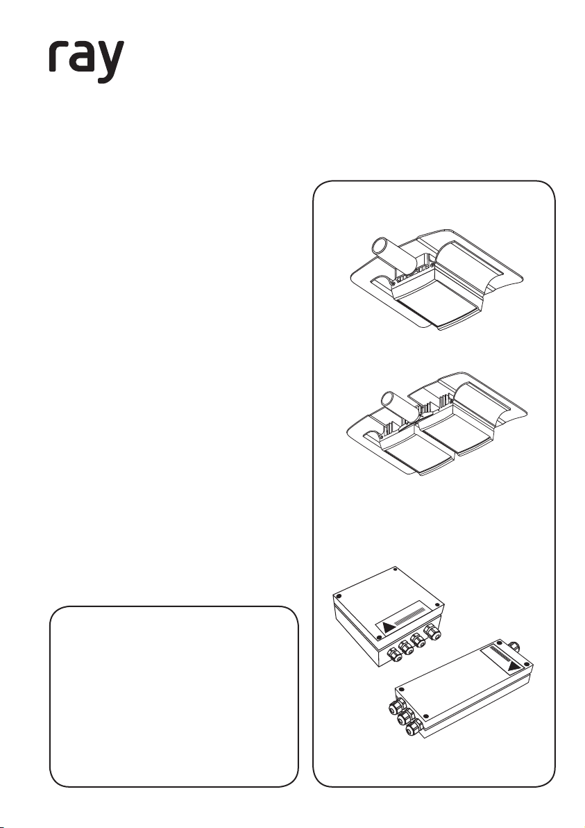
Raytec RAYLUX URBAN UBA48 User manual

Installation Steps
1. Feed cable through bracket solution
2. Mount Illuminator
3. Mount PSU
4. Connect Illuminator to PSU
5. Connect Photocell to PSU
Set Up Steps
1. Locate unit(s) as advised in
lighting design
2. Position unit to provide illumination
down onto a scene
3. If using UBA48 or UBA32 model,
adjust the horizontal angle via
Adaptive illumination™
4. Tighten all fixings
Package Contents
1. Illuminator
2. Power Supply (PSU)
3. Illuminator cable (5m)
4. Photocell cable (5m)
illuminators installation guide
LUX URBAN
1
RAYLUX URBAN illuminators
PSU
Overview
This installation guide provides instructions for installing the RAYLUX
URBAN series of White-Light illuminators.
!
WARNING
!
WARNING
Version 1.1
GOLDEN RULES:
1. Ensure PSU lid orientation has
warning label in line with main
input glands
(see PSU diagram, right)
2. Ensure operating voltage is
correct for unit being installed
3. Ensure PSU is fully water tight
UBF Range
UBA Range

!
Isolate mains before
removing cover
Mount PSU to
flat surface or
inside column
Install in a well
ventilated area
Do not continually
stare at lamp
Specifications subject to change without notice. Installation to be carried out by suitable trained and qualified personnel.
2
Photocell input
LED output 2 Mains input
LED output 1
1.5m
LED output 2
LED output 1 Photocell input
Mains input
LED output cable
5m (16.4ft)
Bracket
Adaptive illumination boltLED illuminator
Photocell mounted on
bracket, with 5m cable
(not supplied – see optional
bracketry – page 5)

Installation
CAUTION:Ensure cable glands
and PSU lid are water tight by
tightening the fixings
!
PSU connections.
4
UBA48 PSU needs to be mounted to a
wall or pole and then connected to the
mains. For all other Urban models, the
slimline PSU will be mounted inside the
column and connected to the mains.
5
Feed cables through bracket
solution – see page 5
Mount and secure illuminator
Ty p i c a l l y C o l u m n M o u n t e d .
Mount PSU – Suitable for
inside most general lighting
columns (excluding UBA48)
can also be mounted ex-
ternally. If external ensure
glands are facing down.
Connect Illuminator to PSU:
Installers can extend or
reduce lead length using
appropriate cable and
weather proof box. Contact
RayLED.
Connect Photocell to PSU.
2
3
4
5
1
1
3
! CAUTION:Red = +ve
Black = -ve
(polarity sensitive)
2
LED output 1
LED output 2
Photocell input
Mains input
(UBA48 Model only)
!
3
LED output 1
LED output 2
Photocell input
Mains input
Column

Set Up
Max x2 +max
5% uplift
!
CAUTION: Do not fully loosen AI bolt.
Note: Power adjust available if required (see PSU diagrams, pages 8-9)
!
4
Locate unit(s) as advised in
lighting design
1Position unit to provide illumination
down onto a scene
2
If using UBA48 or UBA32 model,
adjust the horizontal angle via
Adaptive illumination™
3Tighten all fixings
4

5
Technical Drawings (Not to scale)
Standard Bracketry
Optional Bracketry
• Tube outreach 125mm
• o/d (outside diameter) 33.7
• i/d (inside diameter) 28
UBF Range UBA Version
Wall Bracket
• Finished in Silver
• o/d (outside diameter) 42.4
• i/d (inside diameter) 34.4
Top Stub Bracket
•Arm o/d 42.4, i/d 39.4
•Bracket Cup o/d 88.9, i/d 84.9
• Fits 76 Spigot
• Twin Version Available
Hockey Bracket
• Arm o/d 42.4, i/d 39.4
• Bracket Cup o/d 88.9, id 84.9
• Fits 76 Spigot
• Twin Version Available

6
Te c h n i c a l S p e c i fi c a t i o n s
UBA48 UBA32 UBF24 UBF16 UBF8
Consumption <80W <50W <40W <25W <15W
Lumen Output* 4700 3100 2350 1600 800
Colour Temp** 6500K 6500K 6500K 6500K 6500K
CRI** 74 - 80+ 74 - 80+ 74 - 80+ 74 - 80+ 74 - 80+
Te m p -50˚C to +50˚C -50˚C to +50˚C -50˚C to +50˚C -50˚C to +50˚C -50˚C to +50˚C
Colour
Silver
other RAL options
available
Silver
other RAL options
available
Silver
other RAL options
available
Silver
other RAL options
available
Silver
other RAL options
available
Angles Various Various Various Various Various
Bracket*** Side Entry Side Entry Side Entry Side Entry Side Entry
IP IP66 IP66 IP66 IP66 IP66
Weight
(inc. PSU) 5kg 4kg 3kg 2.5kg 1.5kg
URBAN Series
OPERATING VOLTAGE: All RayLED units are supplied complete with a dedicated
(Universal 100-240V AC auto sensing) current controlled PSU c/w adjustable photocell,
power and telemetry input.
Note: Full independent photometry available on request.
* Lumen output depends upon final lens selection. Lumen output shown based on average between 10 and 50 degree angles.
** Cool White as standard - Warm White options available. CRI published reflects range between Cool and Warm White.
*** See page 5 for optional bracketry.

7
PSU Specifications
UBA48 UBA32 UBF24 UBF16 UBF8
Input AC-100-240
universal<80W
AC-100-240
universal<40W
AC-100-240
universal<40W
AC-100-240
universal<20W
AC-100-240
universal<10W
Fuse 2.5A antisurge 2.5A anti-surge 2.5A anti-surge 1A anti-surge 1A anti-surge
Typical Output
(Standard) 4.2A @ 14V 2.8A @ 14V 2.1A @ 14V 1.4A @ 14V 0.7A @ 14V
Adjustable Power 10% - 100% 10% - 100% 10% - 100% 10% - 100% 10% - 100%
Weight 1.85kg
(4.1 lbs)
0.7kg
(1.5 lbs)
0.7kg
(1.5 lbs)
0.7kg
(1.5 lbs)
0.7kg
(1.5 lbs)
Dimensions
L x W x D
160x160x81mm
(6.3x6.3x3.2”)
248x78x55mm
(9.7x3x2.1”)
248x78x55mm
(9.7x3x2.1”)
248x78x55mm
(9.7x3x2.1”)
248x78x55mm
(9.7x3x2.1”)
URBAN Series PSU
Power Supply Features
STANDARD PSU
• Input: Universal 100-240V
AC auto-sensing
• Output: Low Voltage
(~14V Current Controlled)
• -50 to +50 C
• IP67
• Telemetry (Volt Free)
• Integrated Photocell (Adjustable)
• Power Adjustable
OPTIONAL PRO PSU
As above plus:
• 12V (1amp) DC Output
• Photocell Following Contact
• Allows Pro IQ module to be tted
(UBA48 ONLY)
PRO SERIES PSU PLUG IN
MODULE:
PRO IQ
• Remote Illumination Adjust
(Dim and Boost)
• Energy Saving Setting
• Deterrent setting
• Timer options
(UBA48 ONLY)

8
STANDARD PSU
URBAN UBA48 Model
Power Supply Diagrams (Not to scale)
Telemetry Input
- requires zero volt,
latched input
Photocell Sensitivity
Photocell Input
Mains Input
100V to 230V AC
Auto-Sensing
LED Output x2
(Polarity Sensitive)
Power Adjust

9
SLIMLINE PSU
URBAN UBA32, UBF24, UBF16, UBF8 Models
LED output 1
LED output 2
Photocell input
Mains Input
Photocell Sensitivity
Power Adjust

10
Trouble Shooting
Ensure all tests are undertaken by a qualified, trained engineer.
Ensure safe working practices are followed at all times
Step 1: Basics
• Check polarity of WHITE-LIGHT Lamp connection
red=+ve, black=-ve
• Check telemetry link is in
• Check photocell is working
• Check power setting pot fully clockwise
• Check mains input
• Check fuse intact
If OK…
Step 2: Lamp Test
Check voltage of lamp o/p approx 14V
Check current of lamp – see instructions for correct current setting
To check lamp current (this must be done while both LED panels
are connected to the PSU) remove +ve LED from both lamp supply
cables and connect multimeter set to 10A current in line with the
lamp. [One lead of multimeter in common (COM), other lead into
10A socket of multimeter; set multimeter to 10A readings]. Refer to
PSU Specications for correct current settings, see pages 7.

11
Step 3: Contact RayLED for further assistance
Note down:
• Model, Angle version + any options
• Serial Number of illuminator and PSU
This manual suits for next models
4
Table of contents
Other Raytec Light Fixture manuals
Popular Light Fixture manuals by other brands

ADJ
ADJ ECO UV BAR 50 IR user manual

Federal Signal Corporation
Federal Signal Corporation BPL26L Installation and maintenance instruction

NERI
NERI Light 106 Instruction booklet

Cooper Lighting
Cooper Lighting Sure-Lites CU-1-R Series Specifications

EXC
EXC ECOLOR EC-C8240N quick start guide

Trilux
Trilux InperlaLP C05 Series Mounting instructions

thomann
thomann Blinder 4-Lite user manual

Eternal Lighting
Eternal Lighting Surge 8 user manual

Lightolier
Lightolier LYEDROP FIXTURE Instructions for installation

thomann
thomann MX-x20 user manual

Larson Electronics
Larson Electronics HALD-24-1X150LED-V3-DIMM instruction manual

GE
GE 10113 installation instructions