Raytheon ST60 User manual

Part1. ST60Instruments–Digital
ST60 Instruments Service Manual 83142-1 i
Part 1. ST60Digitalinstruments
D4468-2

Part1. ST60Instruments–Digital
ii ST60InstrumentsServiceManual 83142-1
Contents
ST60Digitalinstrument explodedview ............................................................................ iv
Chapter1. ST60 Speedinstrument ................................................................................... 1
Disassembly/reassembly ............................................................................................ 1
Self-testprocedure...................................................................................................... 1
Selfteststage 1 ................................................................................................. 1
Self-teststage2 ................................................................................................. 1
Self-teststage4 ................................................................................................. 2
ST60Speedspare parts list.......................................................................................... 3
ST60Speed PCBdetails ............................................................................................. 4
Input/Outputsignals.......................................................................................... 4
ST60Speedcircuitdiagram ............................................................................... 5
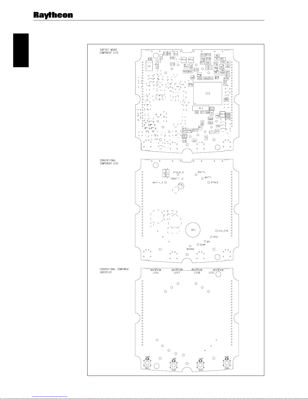
ST60Speed PCBlayout ............................................................................................. 6
ST60Speed PCBcomponentlist ....................................................................... 7
Chapter2. ST60 Depthinstrument ................................................................................... 9
Disassembly/reassembly ............................................................................................ 9
Self-testprocedure...................................................................................................... 9
Selfteststage 1 ................................................................................................. 9
Self-teststage2 ................................................................................................. 9
Self-teststage4 ............................................................................................... 10
ST60Depthspare parts list........................................................................................ 11
ST60Depth PCBdetails ........................................................................................... 12
Input/Outputsignals........................................................................................ 12
ST60Depthcircuitdiagram ............................................................................. 13
ST60Depth PCBlayout ........................................................................................... 14
ST60Depth PCB componentlist ..................................................................... 15
Chapter 3. ST60 Multi instrument .................................................................................. 17
Disassembly/reassembly .......................................................................................... 17
Self-testprocedure.................................................................................................... 17
Selfteststage 1 ............................................................................................... 17
Self-teststage2 ............................................................................................... 17
NMEAI/OTesting.......................................................................................... 18
ST60Multi spare partslist......................................................................................... 19
ST60Multi PCBdetails ............................................................................................ 20
Input/Outputsignals........................................................................................ 20
ST60Multicircuitdiagram.............................................................................. 21
ST60Multi PCBlayout ............................................................................................ 22
ST60Multi PCBcomponent list ...................................................................... 23

Part1. ST60Instruments–Digital
ST60 Instruments Service Manual 83142-1 iii
Chapter 4. ST60 Tridata instrument............................................................................... 25
Disassembly/reassembly .......................................................................................... 25
Self-testprocedure.................................................................................................... 25
Selfteststage 1 ............................................................................................... 25
Self-teststage2 ............................................................................................... 25
Self-teststage4 ............................................................................................... 26
ST60Tridatasparepartslist ...................................................................................... 27
ST60Tridata PCB details.......................................................................................... 28
Input/Outputsignals ........................................................................................ 28
ST60Tridatacircuitdiagram ........................................................................... 29
ST60Tridata PCB layout .......................................................................................... 30
ST60Tridata PCBcomponentlist .................................................................... 31

Part1. ST60Instruments–Digital
iv ST60InstrumentsServiceManual 83142-1
ST60Digitalinstrumentexplodedview
1234
1. Facia bezel
2. Keypad
3. Facia
4. Inner keypad
5. Label
6. LCD display
7. Diffuser
8. Reflector
9. PCB assembly
10. Case seal
Note:
A. It is recommended that a new case seal (10)
is fitted on re-assembly.
11. Rear case
12. Washer (x3)
13. Screw (x11)
14. Label (rear case)
15. Gasket
16. Flush mount bezel
17. Screw (x4)
18. Flush mount seal
19. Rear bracket
56
12
(x3) 13(x3)
Torque 0.22Nm(2lbin)
13(x8)
Torque 0.22Nm(2lbin)
7 8 9 10 (Note A) 11 14 15
D4448-1
2 Assembly16
17(x4)
Torque 0.33Nm (3lb in) 18 19
Flush mounting
Figure 1: ST60Speed, Depth,Multi andTridataDigitalInstrumentexploded view

Part1. ST60Instruments–Chapter1.Speed
A22001
ST60 Instruments Service Manual 83142-1 1
Chapter1. ST60Speedinstrument
Disassembly/reassembly
Onreassembly(refer to Figure1),it is importantthatthePCB assemblymoduleis
fixedtothefacia(3)usingatorqueof0.22Nm(2lb in). Similarly,fixingtherearcase
(11)tothe facia (3)mustalsobetorqued to0.22Nm(2lbin).
Note:Failuretopracticeusingtherecommendedtorquesmayresultindamageto
thefaciainserts.Itisalso recommendeda newcaseseal(10)is fittedonreassembly.
Self-test procedure
TheST60Speedinstrument has built-inself-testfunctionstoaid fault diagnosis.
Toaccessself-testmode,pressKey1andKey4togetherfor4seconds.Whenthe
unitbeeps,immediately press Key3andKey 4 togethermomentarily.The unit will
enterself-teststage1.
Selfteststage 1
A. Theunitshoulddisplay “TEST1”
B. AudibleBeep for 1second.
C. Therewillbea SeaTalktransmissiontocheckthetransmit/receivecircuits.
D. TheEEPROMis tested.
Thefollowingfailurecodesmaybegenerated:
Message FailureMode Action
FAIL1 SeaTalkRx/Tx Checkfordamagedbucketconnectors/rear-casepins.
CheckSeaTalkinterfacecomponentsaroundTR1,TR2andTR3.
FAIL2 EEPROMfailure ReplaceEEPROM(IC2)
Ifthereisnoaudiblebeep,checkTR11andRN3andthe buzzerfordamage.Ifthe
beepisquiet, check R21.
Ifall test pass,“PASS”is shownonthe display. Press Key1andKey2 together
momentarilytoprogress to self-teststage2.
Self-test stage 2
A. Theunitshould display “TEST2”for1 second.
B. Illuminationwillchangebetweenlevel0andlevel3everysecond.
C. Anykeypresssoundcause audible beep.
D. LCDsegmentswillcyclethroughthefollowingsequence:
D4479-1
1234

Part1. ST60Instruments–Chapter1.Speed
A22001
2ST60InstrumentsServiceManual 83142-1
Nofailcodesaregeneratedsincestage2isan audio/visual check.The followingcan,
however,beusedasa guidetoisolateaproblem:
FailureMode Action
Noillumination CheckTR14,TR13,TR15andassociatedcomponents.
CheckallLEDs.
KeypadIlluminationfailure CheckTR14,TR13,R22andR23.
(LCDilluminationwillalsobedegraded) CheckLED1-6foropencircuit.
KeypadilluminationOK CheckTR14,TR15,RN3,R24.
butdegradedLCDillumination CheckLED7and8foropencircuit.
Nobeepwhenkeypressed Replacekeyswitch.
LCD segment(s) missing completely Check LCD solder pins for poor/dry joints.
CheckIC3forunsolderedpins.
FaintLCDsegments CheckLCDpinsforshorts.
CheckIC3forshorts.
PressKey 1andKey2 together momentarilytoprogressto self-teststage4(stage 3
notsupportedon thisinstrument).
Self-test stage 4
Note:Aknowngoodtransducer must beconnectedforthistest.
A. Theunitshoulddisplay‘TEST4’for1 second.
B. Transducertestisperformed.
Spinthepaddle wheel within15secondsof entering thistest.Ifthe interface is
workingcorrectly,“PASS” will beshown.Otherwise“FAIL10”is shown.
Ifthetest fails, do thefollowing:
Check FailureMode Action
Voltageat12V_SPD Novoltageorlowvoltage(<11.0) CheckTR17,TR20,R63andR64.
with12Vbatterysupply.
L7 Opencircuit ReplaceL7
D3 Opencircuit ReplaceD3
VoltageatTEMPpin Outsideacceptablerangeof CheckL9foropencircuit
0.76to1.00V(18-25degreesC) CheckR14
AVREF Outsideacceptablerangeof CheckTR4.
2.5V+/-0.25v CheckR74,17
PressKey1andKey2togethermomentarilytoexitself-test.

Part1. ST60Instruments–Chapter1.Speed
A22001
ST60 Instruments Service Manual 83142-1 3
ST60Speedsparepartslist
Theitemnumbersreferto
Figure1: ST60Digitalinstrument explodedview
Item Spare/AccessoryDescription PartNo. Comments
1 Faciabezel A25001
– Suncover,standard A25004 Notillustrated
2 Keypad,Speed A28019 Packof5
Faciawithcaseseal,
including
A28013
3 Facia
10 Caseseal SeeA28027
12 Washer(x3)
13 Screw(x11) Torqueto0.22Nm(2lbin)
Innerkeypad,
including
A28022
4 Innerkeypad
10 Caseseal SeeA28027
12 Washer(x3)
13 Screw(x11) Torqueto0.22Nm(2lbin)
5 Displaylabel,Speed A28031 Packof5
6 LCDdisplay,Speed A28023 AlsoservestheDepth
orMulti
PCBassembly,Speed,
including
A28010 Assembledmoduleconsisting
of items 6, 7, 8, 9.
6 LCDdisplay,Speed SeeA28023
7 Diffuser
8 Reflector
9 PCBassembly,Speed
10 Caseseal SeeA28027
12 Washer(x3)
13 Screw(x11) Torqueto0.22Nm(2lbin)
10 Caseseal A28027 Packof5
Rearcaseassembly,
including
A28014
10 Caseseal SeeA28027
11 Rearcase
13 Screw(x8) Torqueto0.22Nm(2lbin)
14 Label,Speed(rearcase) A28035 Packof5
15 Gasket A28028 Packof5
16 Flushmountbezel A25002
Flushmountkit,
including
A25003
– Suncover,flushmount Notillustrated
16 Flushmountbezel SeeA25002
17 Screw(x4) Torqueto0.33Nm(3lbin)
18 Flushmountseal
19 Rearbracket

Part1. ST60Instruments–Chapter1.Speed
A22001
4ST60InstrumentsServiceManual 83142-1
ST60SpeedPCB details
Input/Output signals
(refertoFigure2.ST60Speedcircuitdiagram)
Rearcase Signal Description
connection
A(Red) BATT+_2 Nominal12VDCsupply
B(Screen) BATT-_2 OV
C(Yellow) STALK_2 Intermittentstreamsof(nominal)12Vpulses
D(Red) BATT+ Nominal12VDCsupply
E(Screen) BATT- OV
F(Yellow) STALK Intermittentstreamsof(nominal)12Vpulses
G(Red) 12V_SPD Approximately11.2VDCout
H(Green) SPD Withtransducerattached,spinningpaddle-wheelproducespulses
approximately11.2VDCinamplitude@5.5Hz/Knot.
J(Screen) OV OV
K(White) TEMP Withtransducerattached,voltagehereisdependanton
temperature. Approximately1.8vat0degreesC.
L(Brown) OVANA OV
Rear case connections to ST60 Speed instrument
D4480-1
S
P
E
E
D
D
E
P
T
H
L
K
J
H
G
ABC
DEF

Part1. ST60Instruments–Chapter1.Speed
A22001
ST60 Instruments Service Manual 83142-1 5
ST60 Speed circuit diagram
D4453-1
Figure 2. ST60 Speed circuit diagram

Part1. ST60Instruments–Chapter1.Speed
A22001
6ST60InstrumentsServiceManual 83142-1
ST60SpeedPCB layout
Taken from Drawing No: 4315-004 Issue: D Date: 01-10-98
D4451-1

Part1. ST60Instruments–Chapter1.Speed
A22001
ST60 Instruments Service Manual 83142-1 7
ST60 Speed PCB
component list
D4452-1
Taken from Drawin
g
No: 4315-004 Issue: D Date: 01-10-98
ST60 SPEED Digital

Part1. ST60Instruments–Chapter1.Speed
A22001
8ST60InstrumentsServiceManual 83142-1

Part1. ST60Instruments–Chapter2.Depth
A22002
ST60 Instruments Service Manual 83142-1 9
Chapter2. ST60Depthinstrument
Disassembly/reassembly
Onreassembly(refer to Figure1),it is importantthatthePCB assemblymoduleis
fixedtothefacia(3)usingatorqueof0.22Nm(2lb in). Similarly,fixingtherearcase
(11)tothe facia(3) must alsobetorquedto 0.22Nm (2lbin).
Note:Failuretopracticeusingtherecommendedtorquesmayresultindamageto
thefaciainserts.Itisalso recommendeda newcaseseal(10)is fittedonreassembly.
Self-test procedure
TheST60Depthinstrument has built-inself-testfunctionstoaidfaultdiagnosis.
Toaccessself-testmode, press Key1 and Key4togetherfor4seconds.When the
unitbeeps,immediately press Key3andKey 4togethermomentarily.Theunitwill
enterself-teststage1.
Selftest stage 1
A. Theunitshould display “TEST1”
B. AudibleBeep for 1second.
C. TherewillbeaSeaTalk transmissiontocheckthetransmit/receivecircuits.
D. TheEEPROMis tested.
Thefollowingfailurecodesmaybegenerated:
Message FailureMode Action
FAIL1 SeaTalkRx/Tx Checkfordamagedbucketconnectors/rear-casepins.
CheckSeaTalkinterfacecomponentsaroundTR1,TR2andTR3.
FAIL2 EEPROMfailure ReplaceEEPROM(IC2).
Ifthereisnoaudiblebeep,checkTR11andRN3andthe buzzerfordamage.Ifthe
beepisquiet, check R21.
Ifall test pass,“PASS”is shownonthe display. Press Key1andKey2 together
momentarilytoprogress to self-teststage2.
Self-test stage 2
A. Theunitshould display “TEST2”for1 second.
B. Illuminationwillchangebetweenlevel0andlevel3everysecond.
C. Anykeypresssoundcause audible beep.
D. LCDsegmentswillcyclethroughthefollowingsequence:
D4479-1
1234

Part1. ST60Instruments–Chapter2.Depth
A22002
10 ST60InstrumentsServiceManual 83142-1
Nofailcodesaregeneratedsincestage 2 is anaudio/visualcheck.Thefollowingcan,
however,beused as aguideto isolate a problem:
FailureMode Action
Noillumination CheckTR14,TR13,TR15andassociatedcomponents.
CheckallLEDs.
KeypadIlluminationfailure CheckTR14,TR13,R22andR23.
(LCDilluminationwillalsobedegraded) CheckLED1-6foropencircuit.
KeypadilluminationOK CheckTR14,TR15,RN3,R24.
butdegradedLCDillumination CheckLED7and8foropencircuit.
Nobeepwhenkeypressed Replacekeyswitch.
LCDsegment(s)missingcompletely CheckLCDsolderpinsforpoor/dryjoints.
CheckIC3forunsolderedpins.
FaintLCDsegments CheckLCDpinsforshorts.
CheckIC3forshorts.
PressKey 1andKey2 together momentarilytoprogressto self-teststage4(stage 3
notsupportedon thisinstrument).
Self-test stage 4
Note:Forthistest,aknowngoodtransducermustbeconnectedand placed inwater
whereanechocanbedetected.Alternatively,and echosimulator can beused.
A. Theunitshould display “TEST4”for1 second.
B. Transducertestisperformed.
Iftheinterface is workingcorrectly, “PASS” willbeshownwithin15seconds.
Otherwise“FAIL8”is shown.
Ifthetest fails, dothefollowing:
Check FailureMode Action
Pulsesatpins8and10ofIC4 Nopulses CheckR68,76,77.
CheckIC4andIC5andreplaceifsuspect(trace
pulsesfromIC3).
PulsesatdrainofTR5 Nopulses CheckL5andR19foropencircuit.
ReplaceTR5.
ReplaceT1.
PulsesatdrainofTR6 Nopulses CheckL5andR19foropencircuit.
ReplaceTR6.
ReplaceT1.
PulsesatDEPTH+andDEPTH- Nopulses CheckC11andC12foropencircuit.
ReplaceT1
Depthreceiveroutputpulses Nopulses Faultdiagnosisofthedepthreceivercircuit
atpin11ofIC5 requiresspecialistknowledgeandtheunits
shouldbereturnedtoRaytheonMarineLtd.
PressKey 1andKey2togethermomentarilytoexitself-test.

Part1. ST60Instruments–Chapter2.Depth
A22002
ST60 Instruments Service Manual 83142-1 11
ST60Depthsparepartslist
Theitemnumbersreferto
Figure1: ST60Digitalinstrument explodedview
Item Spare/AccessoryDescription PartNo. Comments
1 Faciabezel A25001
– Suncover,standard A25004 Notillustrated
2 Keypad,Depth A28019 Packof5
Faciawithcaseseal,
including
A28013
3 Facia
10 Caseseal SeeA28027
12 Washer(x3)
13 Screw(x11) Torqueto0.22Nm(2lbin)
Innerkeypad,
including
A28022
4 Innerkeypad
10 Caseseal SeeA28027
12 Washer(x3)
13 Screw(x11) Torqueto0.22Nm(2lbin)
5 Displaylabel,Depth A28030 Packof5
6 LCDdisplay,Depth A28023 AlsoservestheSpeed
orMulti
PCBassembly,Depth,
including
A28009 Assembledmoduleconsisting
ofitems6,7,8,9.
6 LCDdisplay,Depth SeeA28023
7 Diffuser
8 Reflector
9 PCBassembly,Depth
10 Caseseal SeeA28027
12 Washer(x3)
13 Screw(x11) Torqueto0.22Nm(2lbin)
10 Caseseal A28027 Packof5
Rearcaseassembly,
including
A28014
10 Caseseal SeeA28027
11 Rearcase
13 Screw(x8)
14 Label,Depth(rearcase) A28036 Packof5
15 Gasket A28028 Packof5
16 Flushmountbezel A25002
Flushmountkit,
including
A25003
– Suncover,flushmount Notillustrated
16 Flushmountbezel SeeA25002
17 Screw(x4) Torqueto0.33Nm(3lbin)
18 Flushmountseal
19 Rearbracket

Part1. ST60Instruments–Chapter2.Depth
A22002
12 ST60InstrumentsServiceManual 83142-1
ST60DepthPCBdetails
Input/Output signals
(refertoFigure3.ST60Depthcircuitdiagram)
Rearcase Signal Description
connection
A(Red) BATT+_2 Nominal12VDCsupply
B(Screen) BATT-_2 OV
C(Yellow) STALK_2 Intermittentstreamsof(nominal)12Vpulses
D(Red) BATT+ Nominal12VDCsupply
E(Screen) BATT- OV
F(Yellow) STALK Intermittentstreamsof(nominal)12Vpulses
G(Black) DEPTH- Intermittentpulsesof200KHz,approximately400uswide,300Vp-p
H(Blue) DEPTH+ Intermittentpulsesof200KHz,approximately400uswide,300Vp-p
J(Screen) DEPTH_GND OV
Rear case connections to ST60 Depth instrument
D4481-1
S
P
E
E
D
D
E
P
T
H
G
H
J
ABC
DEF

Part1. ST60Instruments–Chapter2.Depth
A22002
ST60 Instruments Service Manual 83142-1 13
ST60 Depth circuit diagram
D4456-1
Figure 3. ST60 Depth circuit diagram

Part1. ST60Instruments–Chapter2.Depth
A22002
14 ST60InstrumentsServiceManual 83142-1
ST60DepthPCBlayout
Taken from Drawing No: 4316-003 Issue: D Date: 01-10-98
D4454-1
ST60
DEPTH
Digital

Part1. ST60Instruments–Chapter2.Depth
A22002
ST60 Instruments Service Manual 83142-1 15
ST60 Depth PCB component list
D4455-1
Taken from Drawin
g
No: 4316-003 Issue: D Date: 01-10-98
ST60 DEPTH Digital

Part1. ST60Instruments–Chapter2.Depth
A22002
16 ST60InstrumentsServiceManual 83142-1
Table of contents
Popular Music Equipment manuals by other brands

WaveReX
WaveReX WaveU operating manual

Aphex
Aphex CX 500 owner's manual

TerraTec
TerraTec SiXPack 5.1+ manual

Flame
Flame X-4 manual

Atlantic Technology
Atlantic Technology Incabinet damping kit installation manual

Audio Design Associates
Audio Design Associates Suite 16 System design & technical documentation