10
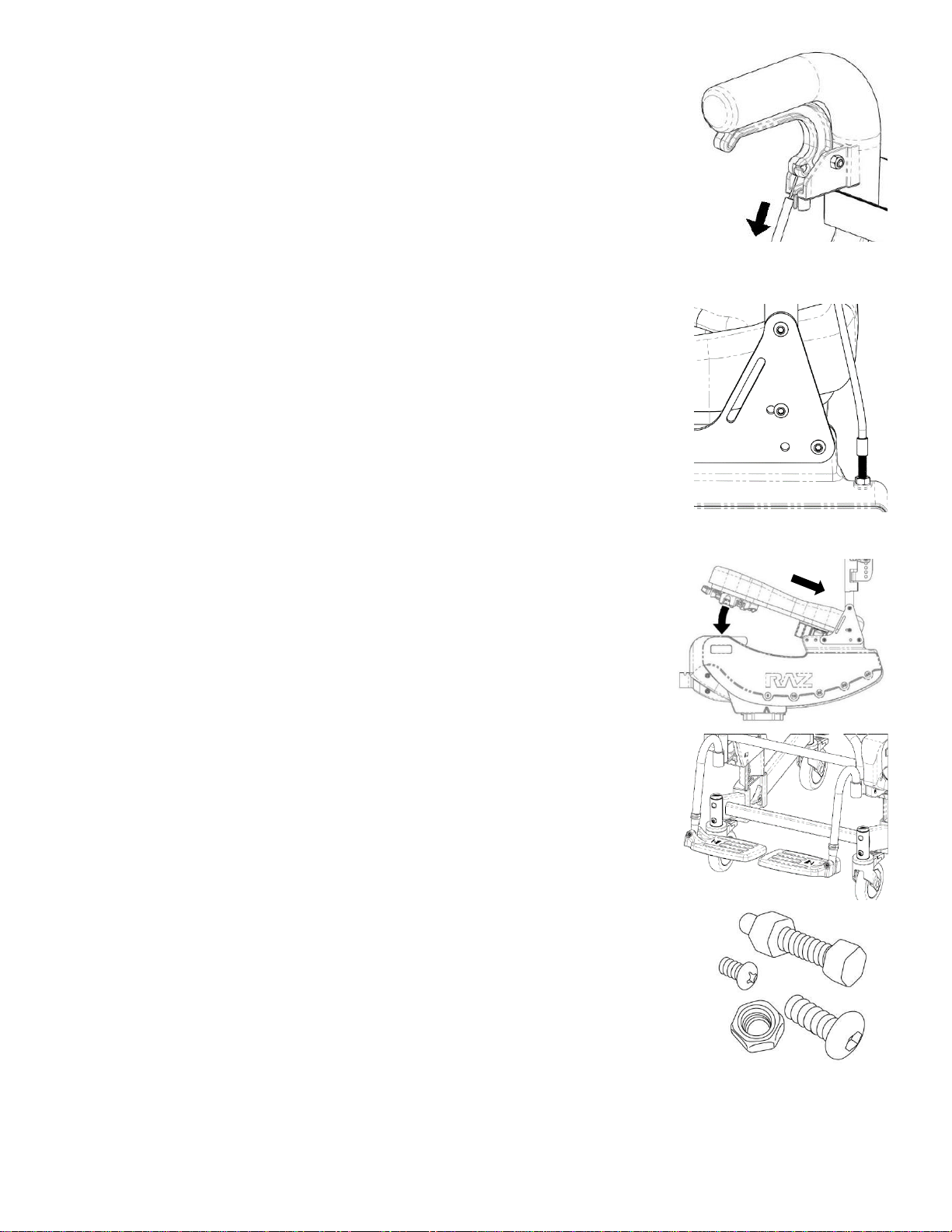
2.3 Cable Installation
1. Squeeze the tilt trigger until it rests against the hand grip.
2. Insert the cable end through the hole on the trigger handle.
TIP: If there is not enough slack in the cable, check to make sure the
cable sheath is fully inserted into the threaded cable fitting at the
bottom end of the cable.
3. Release the trigger handle and pull the cable sheath downward to
expose the cable wire.
4. Thread the cable wire through the housing slit.
5. Insert the tip of the sheath into the bottom of the trigger housing and release.
6. Repeat steps 1-5 for the other side.
NOTE: Before the chair is used, it is important to check that each cable is properly
adjusted and the tilt lock system is functioning as designed. With the chair tilted to
approximately 20° and while squeezing the tilt trigger controlling the lock mechanism
on one side of the chair, try to change the tilt angle of the chair in both directions. If
the tilt angle can be changed while the one trigger is being squeezed, the cable
controlling the tilt lock on the other side needs to be adjusted. To do so, loosen the
jam nut and then turn the threaded cable fitting 1-3 complete rotations clockwise.
Test again (re-adjust cable fitting if needed) and tighten the jam nut against the side
panel if the chair does not move during the test. Repeat the test for the other tilt
trigger and adjust if needed. If a tilt lock pawl clicks against the notches in the locking
plate as the chair is tilted with both tilt triggers squeezed, one or both of the cables
require adjustment. On the side that is making the noise, loosen the jam nut and turn
the cable fitting 1-3 complete rotations - counter-clockwise. Tilt the chair and listen
for the clicking noise. Tighten the jam nut on the cable fitting if the noise has stopped.
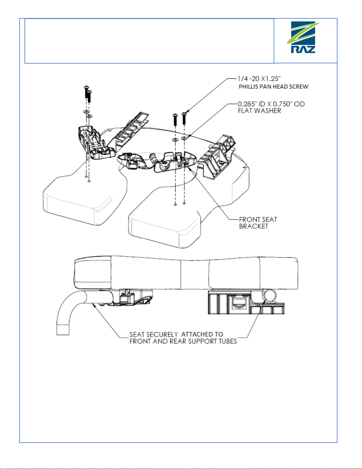
2.4 Raz Seat Installation
1. Ensure that the front brackets are in the open position.
2. Slide the rear of the seat over the rear seat support tubes as the front
of the seat is lowered onto the frame. Check to ensure the rear seat
brackets hook below rear seat support tubes.
3. Continue lowering the front of the seat until the front seat brackets
nestle onto the front seat support tubes.
4. Secure the seat in place by closing the front seat brackets.
5. Reverse steps 1 to 4 to remove the seat from the frame.
2.5 Installation of Adjustable Foot Supports
1. Remove the foot supports (footrests) from the accessory box.
2. Place the foot support hanger tubes into the receivers.
If the hanger tubes are directed forward, the pins on the tubes will
engage with the grooves in the receivers and lock in place.
2.6 Fastener Installation
All fasteners should be installed securely by hand and not with power
tools. The speed and torque of the power tools can cause the fasteners to
seize and permanently cold weld in place. It is also recommended that
liquid soap (dish / hand soap) be added to the screw thread to help prevent
the fasteners from seizing. Lock nuts that are removed for any reason may
need to be replaced rather than re-used. Check performance of lock nuts
when re-attaching to screw. There should be significant, detectable
resistance when tightening. If not, replace the lock nut with a new one. It
is advisable to check monthly, that all fasteners are properly tightened and
that all adjustable components are secured in place.