LCD INSTALLATION AND OPERATION INSTRUCTIONSPage 6
All Air From Outside The Building
When installed in a confined space without utilizing
the intake air option two permanent openings
communicating directly with, or by ducts to, the outdoors
or spaces that freely communicate with the outdoors must
be present. The upper opening must be within 12 in,
305 mm of, but not less than 3 in, 76 mm from, the top of
the enclosure.The bottom opening must be within 12 in,
305 mm of, but not less than 3 in, 76 mm from, the bottom
of the enclosure.
Where directly communicating with the outdoors
or communicating with the outdoors through vertical
ducts, each opening shall have a minimum free area
of 1 in2/4000 Btu/hr, 550 mm2/kW of the total input
rating of all of the equipment in the enclosure.
Where communicating with the outdoors through
horizontal ducts, each opening shall have a minimum
free area of 1 in2/2000 Btu/hr, 1100 mm2/kW of the total
input rating of all of the equipment in the enclosure.When
louvers and screens are used, they must have the same
cross-sectional area as the free area of the opening to
which they connect.
When calculating the free area necessary to meet
the make-up air requirements of the enclosure,
consideration must be given to the blockage effects
of louvers, grills and screens. Screens must have a
minimum mesh size of 1/4 in, 6.4mm. If the free area
through a louver or grill is not known, ducts should be
sized per Table 3.
Table 3 - Make-up Air Louver Sizing
Required Cross Sectional Area
Input 1/4 in 6.4 mm
75% Free Area
25% Free Area
(MBH) Wire Screen
Metal Louvers
Wooden Louvers
in2cm2 in2cm2 in2cm2
225 57 363 75 484 225 1452
300 75 484 100 645 300 1935
399 100 645 133 858 399 2573
600 150 968 200 1290 600 3870
750 190 1210 250 1613 750 4840
1050 263 1696 350 2258 1050 6773
1200 300 1936 400 2580 1200 7740
1480 370 2388 494 3182 1480 9546
1650 413 2662 550 3548 1650 10,643
1970 493 3179 657 4236 1970 12,707
2300 575 3711 767 4945 2300 14,835
Canadian installations must comply with CSA B149.1
when air supply is provided by natural air flow from the
outdoors for natural draft, partial fan-assisted, fan-
assisted, or power draft-assisted burners, there shall
be a permanent air supply opening(s) having a cross-
sectional area of not less than 1 in2per 7,000 Btuh
(310 mm2per kW) up to and including 1 million Btuh,
plus 1 in2per 14,000 Btuh (155 mm2per kW) in excess
of 1 million Btuh.
Intake Air Option - General Guidelines
This configuration provides combustion air directly to the
boiler/water heater’s air intake using a dedicated pipe
to obtain combustion air from the outdoors. Combustion
air can be drawn in horizontally through an outside wall
or vertically through the roof, see Figures 4, 5, 6 & 7.
WARNING: Common intake air systems may
be used to provide the common duct is sized
properly and an intake combustion air damper
is installed in the intake air pipe of each heater.
Improper installation can result in excessive
levels of carbon monoxide which can cause
severe personal injury or death!
Single wall galvanized smoke pipe, single wall aluminum
pipe or flexible aluminum pipe can be used for the
in-take air pipe. It must be sized per Table 4. All joints
in metal combustion air systems must be secured using
corrosion resistant fasteners and sealed using a suitable
Silicon caulk or tape. The combustion air system
MUST be supported by the building structure not
the boiler/water heater.
Table 4 - Combustion Air Pipe Sizing
Model Size Pipe Diameter
in mm
225 - 300 5 127
400 6 152
600 - 750 8203
1050 10 254
1200 - 2300 12 305
CAUTION: A stack damper interlocked with the unit
should be installed in the intake air pipe when the
infiltration of sub-freezing air could occur, otherwise
the unit could freeze up voiding the warranty!
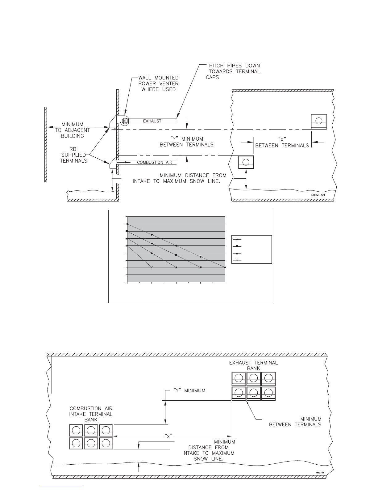
Intake Air Option - Horizontal Guidelines
The maximum equivalent length for the horizontal
combustion air pipe on installations that used the Direct
Vent option is 35 ft, 10.8 m. The maximum equivalent
length for the horizontal combustion air pipe on
installations that use the Horizontal Vent option is 100 ft,
30.5 m. Each 90° elbow and the combustion air terminal
are equal to 10 linear ft, 3.0 mof pipe. If horizontal runs
exceed 5 ft, 1.5 m they must be supported at 3 ft, 0.9 m
intervals with overhead hangers.The certified combustion
air terminal from RBI must be used and installed as
shown in Figures 4 and 5.
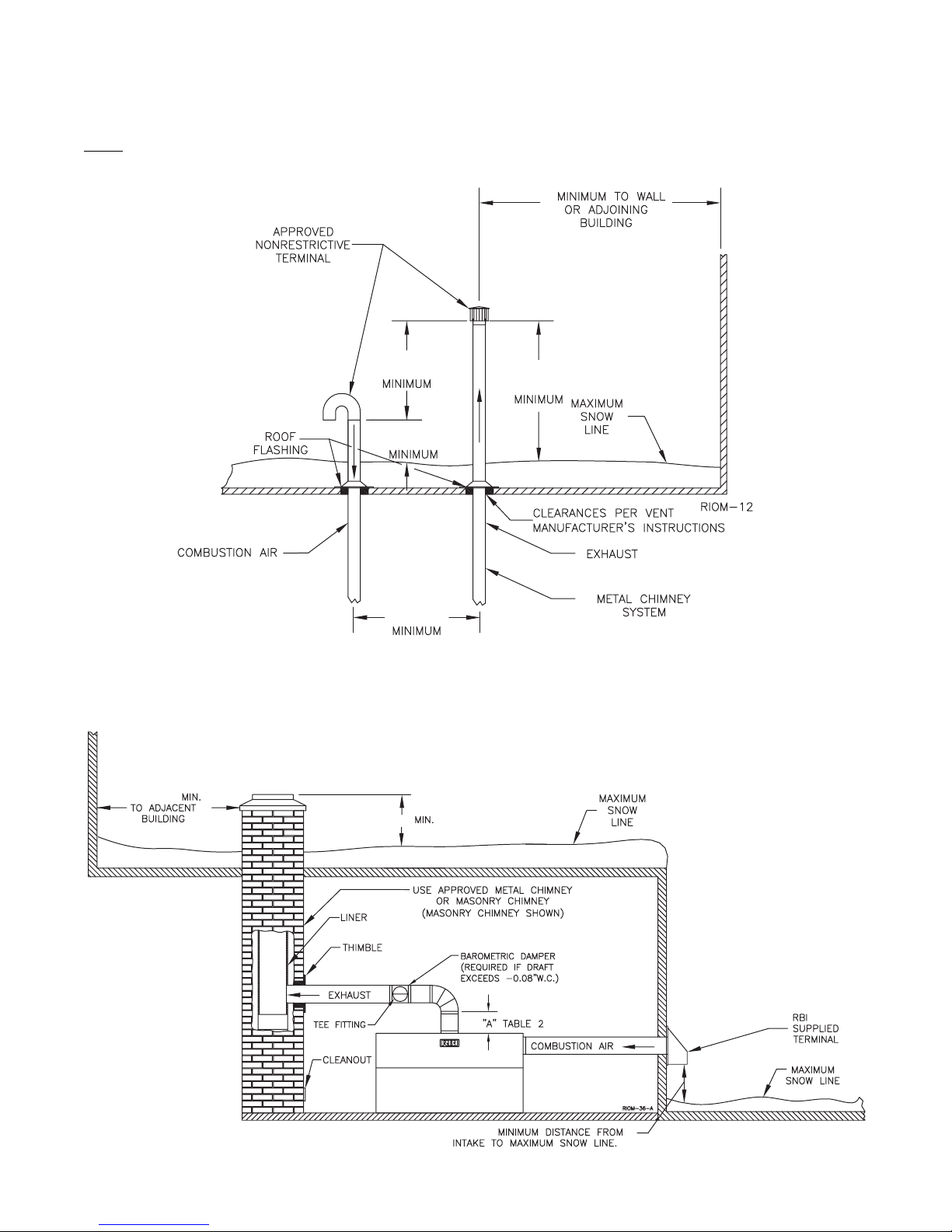
Intake Air Option - Vertical Guidelines
The maximum length for the vertical combustion air
pipe is 30 ft, 9.1 m plus two 90° elbows. A listed,
nonrestrictive combustion air cap must be used. The
combustion air cap must terminate as shown in Figure
6. The penetration point in the roof must be properly
flashed and sealed.


 Operation and maintenance instructions")