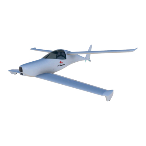
rc3Dprint PILATUS PC-6 PORTER User manual

J
PRINTING AND
ASSEMBLY

THANK YOU
Thank you for purchasing the Pilatus PC-6 Porter. These models take many hours of work to
make available to you so please don’t share the STL files with others. Send them to
www.rc3print.com so they can purchase them at a reasonable price. This enables us to keep
making improvements and bring you new aircraft.
This document aims to help you print and assemble your aircraft. Our designs are made to
be simple “print and glue builds”. If you follow the instruction you will end up with a
beautiful flying machine. That being said 3D printers often have many differences so you
may need to tweak settings to get the best results.
Included in they document you will find Cura profiles and layouts for each part and
assembly instructions. Many of the components in the design are solid bodies, this has some
advantages over hollow bodies in that you can adjust some settings such as wall thickness,
infill percentage, etc. As such we recommend using Cura to slice the files. The walls of these
solid bodies are single line 0.4mm thickness to reduce weight with most parts then double
walled for strength.
As you are printing and assembling the model yourself we take no liability for damage or
loss resulting from your use of these files. Please fly responsibly and follow all local laws.
Share your results on instagram and tag @rc3dprint for discount codes on future orders

PARTS LIST
REQUIRED
Motor - Overlander T2836 or similar - ESC and LIPO - 3S battery minimum
4 - Channel radio kit.
4 x 9g servo + 2 x servo extension
2 x BBQ Skewers + Elastic Bands for wing mounting
8 x servo screws for mounting motor and wing struts
3m of 1.1m diameter piano wire for control rods, landing gear and hinges
3 x wheels for landing gear
Assorted heat shrink tubing or electrical tape
CA glue
Hot glue (optional)

INCLUDED STL. FILES
FUSELAGE
WING

HORIZONTAL STABILISER
VERTICAL STABILISER & MISC

SPECIFICATIONS
Wing Span
1200mm
Flying Weight
(2200mAh 3S): 1000g
Wing Loading
53 g/dm2 17.4 oz/sq.ft
Wing Cube Loading
12.5
Channels
4 Channel
Centre of Gravity
1.5-2.5cm behind leading
edge. Approx the wing strut join
1200
800.42

PRINTING PROFILES
Please save the following profiles in Cura, ready to be used as required for the selected part
to be printed.
Load a generic PLA profile (or PETG for profile 3) into Cura for your printer, then change
the following from the default options Profile 1.
PLA PROFILE 1
Save this profile as PROFILE 1
Wall Thickness
0.4mm
Wall line count
1
Top/Bottom Pattern
Lines
Infill Density
3
Infill Pattern
Cubic
Printing Temperature
215 -230C
Build Plate Temperature
60C (optional)
Fan Speed
20% Maximum
Generate Support
No
Build PLate Adhesion
Brim (recommended)

PLA PROFILE 2 - MOUNT
Save this profile as PROFILE 2
PETG PROFILE 3 - BACKPLATE
Save this profile as PETG PROFILE 3
Wall Thickness
0.4mm
Wall line count
1
Bottom Thickness
2mm
Top/Bottom Pattern
Lines
Infill Density
10
Infill Pattern
Cubic
Printing Temperature
215 -230C
Build Plate Temperature
60C (optional)
Fan Speed
20% Max
Generate Support
No
Build PLate Adhesion
Skirt
Wall Thickness
1.2mm
Wall line count
3
Top/Bottom Pattern
Lines
Infill Density
20
Infill Pattern
Cubic
Printing Temperature
240C
Build Plate Temperature
70C
Generate Support
No
Build PLate Adhesion
Skirt (recommended)

ASSEMBLY
The animation here shows you the order in which to glue the parts together. I know how
excited we all get and like to bound ahead without looking at instructions so here are
1. LEAVE ONE ELEVATOR END CAP UNTIL FINAL
ASSEMBLY AS THE ELEVATOR HINGE IS GLUED IN
PLACE BY THIS PART.
2. ALL WING FLAP/AILERON-SERVOS NEED TO BE IN
PLACE BEFORE GLUING THE WING PIECES TOGETHER.
3. THE AILERON NEEDS TO BE IN PLACE BEFORE
GLUING THE WINGTIP ON.
•Throughout the build, adhesions should be carefully removed and faces to be glued
together should be sanded gently first to ensure good contact.
•Build the tail section first, leaving one of the Elevator End Cap’s until the elevator is in
place with the hinge fitted. Then add the end cap. The rudder hinge passes through the
small hole between the horizontal stabilisers. Use the rudder hinge when gluing the
Horizontal Stab in pace to make sure it is central. Don’t glue the rudder hinge to the
rudder until the end when the tail wheel is in place.
3 MUST READ POINTS

•Assemble the other fuselage sections together with CA glue, ensuring a strong join.
When gluing the Motor Cowling to the Nose, you may want to put the motor mount
screws in place to help hold it. This will also ensure everything is lined up properly. This
join is critical to avoid your motor flying offthe model!
•You can attach the tail section to the fuselage now. For the rudder hinge, cut your wire
with enough excess to bend for a tail gear as shown. Alternatively, you can simply bend
the wire to form a skid for landing. If you want the wheel or skid to control direction on
the ground then you need glue the hinge to the rudder. Hold the rudder upside down and
drip several drops of CA glue into it. Then push the rudder hing through the bottom of
the tail into the rudder and out of the top with the rudder misaligned so you can wipe
away excess CA glue from the hinge. Then, retract the hinge, line up the rudder again and
push all the way through the Vertical Stab Top back into the rudder end cap. Make sure to
line the skid or wheel up with the rudder and leave for a few hours to dry. CA glue
doesn’t bond quickly to metal so you must leave it alone. Every now and then check that
the hinge isn’t stuck to the Horizontal Stab and tail section and you can move the rudder
and wheel together.
•For the wing build you have two options, with flaps and without.
Without Flaps:
•Place your servo into the Wing Outboard section and make sure you have enough servo wire to run all
the way to the body. With the servo in place (I usually use a blob of (not too) hot glue) and the servo
wire running through the channels you can glue the Wing Outboard to the Wing Inboard. These joins
are critical, make sure they are well sanded and take your time. Run the servo wire through the channel
into the Wing Centre and out through the gap in the middle, then glue the Wing Outboard to the Wing
Centre. Measure out your aileron hinge wire, then, with the Aileron and hinge in place glue to the
Wingtip to the wing. Repeat for the other side of the wing.
With Flaps
• For the wing with flaps it is recommended to use an 8mm (dia) round carbon spar. Once all the parts
are printed check for fit with the carbon, if it is too tight you can use an 8mm drill bit to gently widen
the gap. The procedure is to build out so start with the wing centre. Then glue the next two wing pieces
either side. Now fit the next part of the wing on but down glue it until you have fitted the servos in
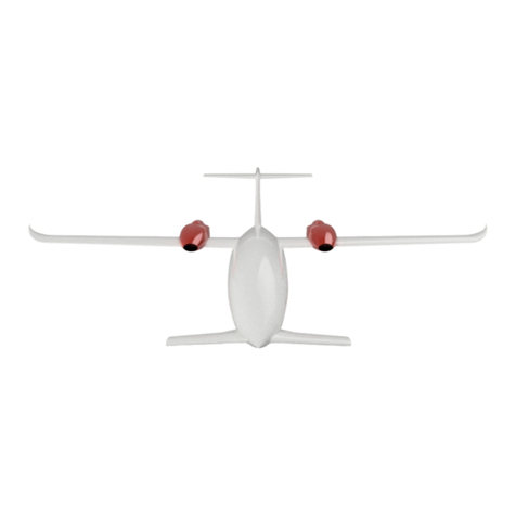
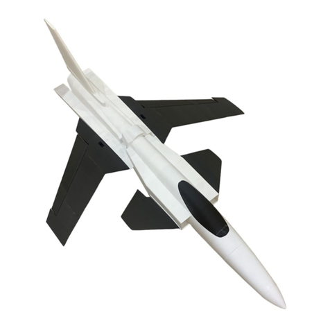
place using some hot glue and fed the servo wires to the centre piece. You will need servo extensions for
the aileron servo, you may need to move the plastic sleeve from the extension plug so that it fits in the
channel. Glue the two flap pieces together. Into the holes on each end of the flap insert a small 1cm piece
of BBQ skewer. Once all the servos are in place you can glue the two inboard wing parts together
without forgetting to put the flap in place. The rest of the wing an aileron is assembled as above.
•Cut your BBQ skewers to length for a normal rubber band wing attachment.
•Dry place your servos in the fuselage so you can cut servo wire to length. Glue the
Elevator Linkage and Rudder Linkage in place. You can now connect up your controls in
the usual manner. I usually use dab of hot glue to hold the servos in place.
•For the landing gear, cut and bend your piano wire using the attached template. Use
electrical tape to hold them together (minus the central spring section) at the axle and
glue them into the fuselage holes using the same method as for the rudder. Leave to dry.
Now attach the central spring section between the two sides, again with electrical tape or
heat shrink wrap. Now you can add your chosen wheels and a dab of hot glue and washer
on the end to keep them on

CURA COMPONENT PLACEMENT
RUDDER
Profile 1
Adhesion: Brim
This is to help prevent the part being
knock over by the extruder.
RUDDER END CAP
Profile 1
Adhesion: Skirt

VERTICAL STABILISER
Profile 1
Adhesion: Brim
This is to help prevent the part being knocked
over by the extruder.
VERTICAL STABILISER TOP
Profile 1
Adhesion: Skirt

ELEVATOR (LEFT & RIGHT)
Profile 1
Adhesion: Brim
This part is tall and thin so requires good
print bed adhesion. Is is possible to print in
one piece but if you are having trouble you
can section it and glue it back together.
ELEVATOR END CAP (LEFT
& RIGHT)
Profile 1
Adhesion: Skirt

STAB FENCE (LEFT &
RIGHT)
Profile 1
Adhesion: skirt
HORIZONTAL STABILISER
(LEFT & RIGHT)
Profile 1
Adhesion: Brim
This part is tall and thin so requires good print
bed adhesion.

TAIL SECTION
Profile 1
Adhesion: Brim or Skirt
AFT FUSELAGE
Profile 1
Adhesion: Brim or Skirt

CENTRAL FUSELAGE
Profile 1
Adhesion: Brim recommended
If you are having problems with the bridging on
the integrated servo mounts, increase the
infill by a few percentage points.
NOSE
Profile 1
Adhesion: Brim recommended

MOTOR COWLING
Profile 2
Adhesion: Skirt
WINGTIP (LEFT & RIGHT)
Profile 1
Adhesion: Skirt

WING OUTBOARD (LEFT
& RIGHT)
Profile 1
Adhesion: Brim
Notice the servo cutout is on top to
avoid the need for supports.
WING INBOARD (LEFT &
RIGHT)
Profile 1
Ahesion: Brim
Note: the aileron hinge hole is touching
the build plate.

AILERON (LEFT & RIGHT)
Profile 1
Adhesion: Brim
WING CENTRE
Profile 1
Adhesion: Brim
Table of contents
Other rc3Dprint Toy manuals

rc3Dprint
rc3Dprint Micro Velocity User manual

rc3Dprint
rc3Dprint QUICKIE User manual

rc3Dprint
rc3Dprint Grumman X-29 User manual

rc3Dprint
rc3Dprint MICRO PEREGRINE FLYING WING User manual

rc3Dprint
rc3Dprint ER-2 User manual

rc3Dprint
rc3Dprint SkiGull User manual

rc3Dprint
rc3Dprint PIAGGIO AVANTI 2 User manual
Popular Toy manuals by other brands

Eduard
Eduard Bristol F.2B Fighter manual

Great Little Trading
Great Little Trading Pat-a-cake Kitchen L4723 Assembly instructions

Bachmann
Bachmann Williams CLASSIC GG-1 instructions

Lindinger
Lindinger SPACE WALKER II Assembly manual

Rail King
Rail King 2-8-0 Steam Freight/ Passenger Set Operation manual

Century Helicopter Products
Century Helicopter Products Swift NX instruction manual