Lindinger SPACE WALKER II User manual

MS:X13
MadeinVietnam.
Kit features
• Ready-made—minimalassembly&finishingrequired.
• Ready-coveredcovering.
• Photo-illustratedstep-by-stepAssemblyManual.
Specifications
Wingspan-----------------------------------------62.2in----------------------------158cm.
Wing area---------------------------------- 635.5 sq.in------------------------ 41 sq.dm.
Approximate flying weight--------------- 4.4 - 5.7lbs---------------------2.0- 2.6kg.
Length----------------------------------------------45.7in---------------------------116cm.
Radio------------------------------------------------------------------------------4channels.
5digital servos (size 24x12mm) Output Torque =1.8 - 2.2 kg - cm.
Need to Complete
Speed Control: 80 - 100 amp.
RecommendedBattery5-cells 18.5V 4000mAh to 5000mAh Li-Po.
ALMOST READY TO FLY
2
“Graphics and specfications may change without notice”.
ASSEMBLY MANUAL

SPACE WALKER II Instruction Manual
2
INTRODUCTION.
Thankyou forchoosing theSPACE WALKER II ARTF .The SPACE WALKER II wasdesigned
withtheintermediate/advancedsportflyerinmind.Itisa scale airplane whichiseasytoflyandquick
to assemble. The airframe is conventionally built using balsa, plywood to make it stronger than the
averageARTF,yetthedesignallowstheaeroplanetobekeptlight.Youwillfindthatmostofthework
has been done for you already. The motor mount has been fitted and the hinges are pre-installed
. Flying the SPACE WALKER II is simply a joy.
This instruction manual is designed to help you build a great flying aeroplane. Please read this
manualthoroughlybeforestartingassemblyofyour SPACEWALKERII.Usethepartslistingbelow
to identify all parts.
WARNING.
Please be aware that this aeroplane is not a toy and if assembled or used incorrectly it
is capable of causing injury to people or property. WHEN YOU FLY THIS AEROPLANE YOU
ASSUME ALL RISK & RESPONSIBILITY.
If you are inexperienced with basic R/C flight we strongly recommend you contact your R/C
supplierandjoinyourlocalR/CModelFlyingClub.R/CModelFlyingClubsofferavarietyoftraining
proceduresdesigned tohelpthenewpilotonhiswaytosuccessfulR/Cflight. Theywillalsobeable
to advise on any insurance and safety regulations that may apply.
ADDITIONAL ITEMS REQUIRED.
Motor:
Radio with five digital servos.
Size = 24 x 12 MM
Torque = 1.8 - 2.2 kg - cm.
Speed control: 80A to 100A.
Battery:5 cells -18.5v 4000 - 5000mah Li -Po

3
NOTE:To avoid scratching your new aero-
planewesuggestthatyoucoveryour
workbench with an old towel. Keep a
couple of jars or bowls handy to hold
the small parts after you open the
bags.
Pleasetrialfitallparts.Makesureyou
havethecorrectpartsandthattheyfit
andarealignedproperlybeforegluing!
This will ensure proper assembly as
the SPACE WALKER II is made
from natural materials and minor ad-
justments may have to be made.
The paint and plastic parts used in
this kit are fuel proof. However, they
arenottolerantofmanyharshchemi-
cals including the following: paint
thinner, cyano-acrylate glue accel-
erator,cyanoacrylategluede-bonder
andacetone.Donotletthesechemi-
calscomein contact withthecolours
onthecoveringandtheplasticparts.
TOOLS & SUPPLIES NEEDED.
Thick cyanoacrylate glue.
30 minute epoxy.
5 minute epoxy.
Hand or electric drill.
Assorted drill bits.
Modellingknife.
Straight edge ruler.
2mm ball driver.
Phillips head screwdriver.
220 grit sandpaper.
90° square or builder’s triangle.
Wire cutters.
Masking tape & T-pins.
Thread-lock.
Paper towels.

SPACE WALKER II Instruction Manual
4
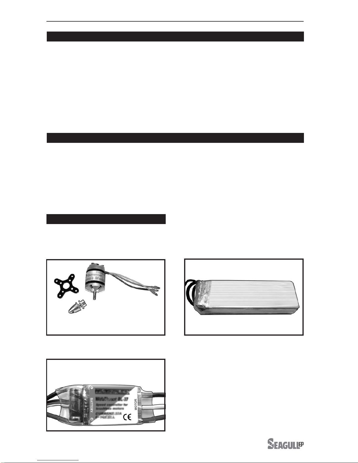
1)Carefullyremove the aileronfromone of
thewingpanels.Notethepositionofthehinges.
2)Removeeach hingefromthe wingpanel
and aileron and place a T-pin in the center of
each hinge. Slide each hinge into the wing
panel until the T-pin is snug against the wing
panel. This will help ensure an equal amount
ofhingeisoneithersideofthehingelinewhen
the aileron is mounted to the aileron.
HINGING THE AILERONS.
3) Slide the wing panel on the aileron until
there is only a slight gap. The hinge is now
centered on the wing panel and aileron.
Remove the T-pins and snug the aileron
against the wing panel.A gap of 1/64” or less
shouldbemaintained betweenthewing panel
andaileron.
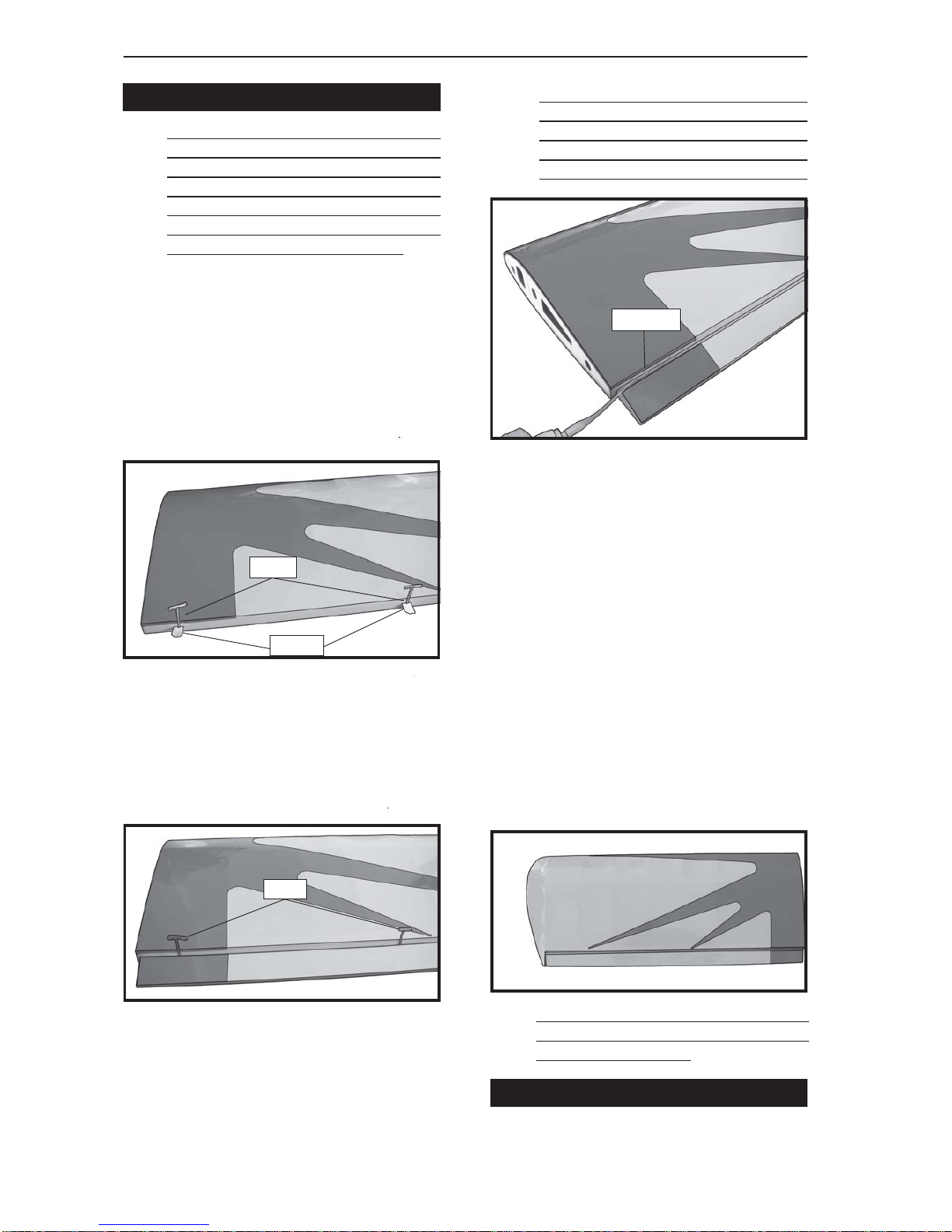
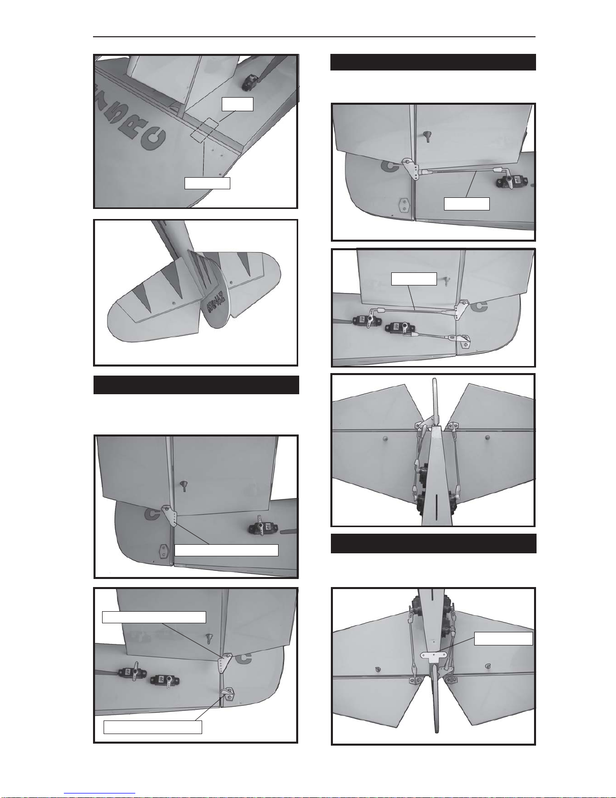
HINGING THE ELEVATOR.
4)Deflect the aileron and completely
saturate each hinge with thin C/A glue. The
aileronsfrontsurfaceshouldlightlycontactthe
wing during this procedure. Ideally, when the
8)After both ailerons are securely hinged,
firmly grasp the wing panel and aileron to
make sure the hinges are securely glued and
cannot be pulled out. Do this by carefully
applying medium pressure, trying to separate
the aileron from the wing panel. Use caution
not to crush the wing structure.
7) Repeat this process with the other wing
panel, securely hinging the aileron in place.
5) Turn the wing panel over and deflect the
aileron in the opposite direction from the
opposite side. Apply thin C/A glue to each
hinge,makingsurethattheC/Apenetratesinto
both the aileron and wing panel.
6) Using C/A remover/debonder and a
papertowel,remove anyexcess C/Agluethat
may have accumulated on the wing or in the
aileronhingearea.
The hinge is constructed of a special
material that allows the C/A to wick or
penetrateanddistributethroughoutthe
hinge, securely bonding it to the wood
structureofthe wingpanel andaileron.
hinges are glued in place, a 1/64” gap or less
will be maintained throughout the lengh of the
aileron to the wing panel hinge line. Glue the elevator hinges in place using the
same tectniques used to hinge the ailerons.
Hinge.
T-pin.
T-pin.
C/Aglue.
Work the aileron up and down several
times to “work in” the hinges and check
for proper movement.
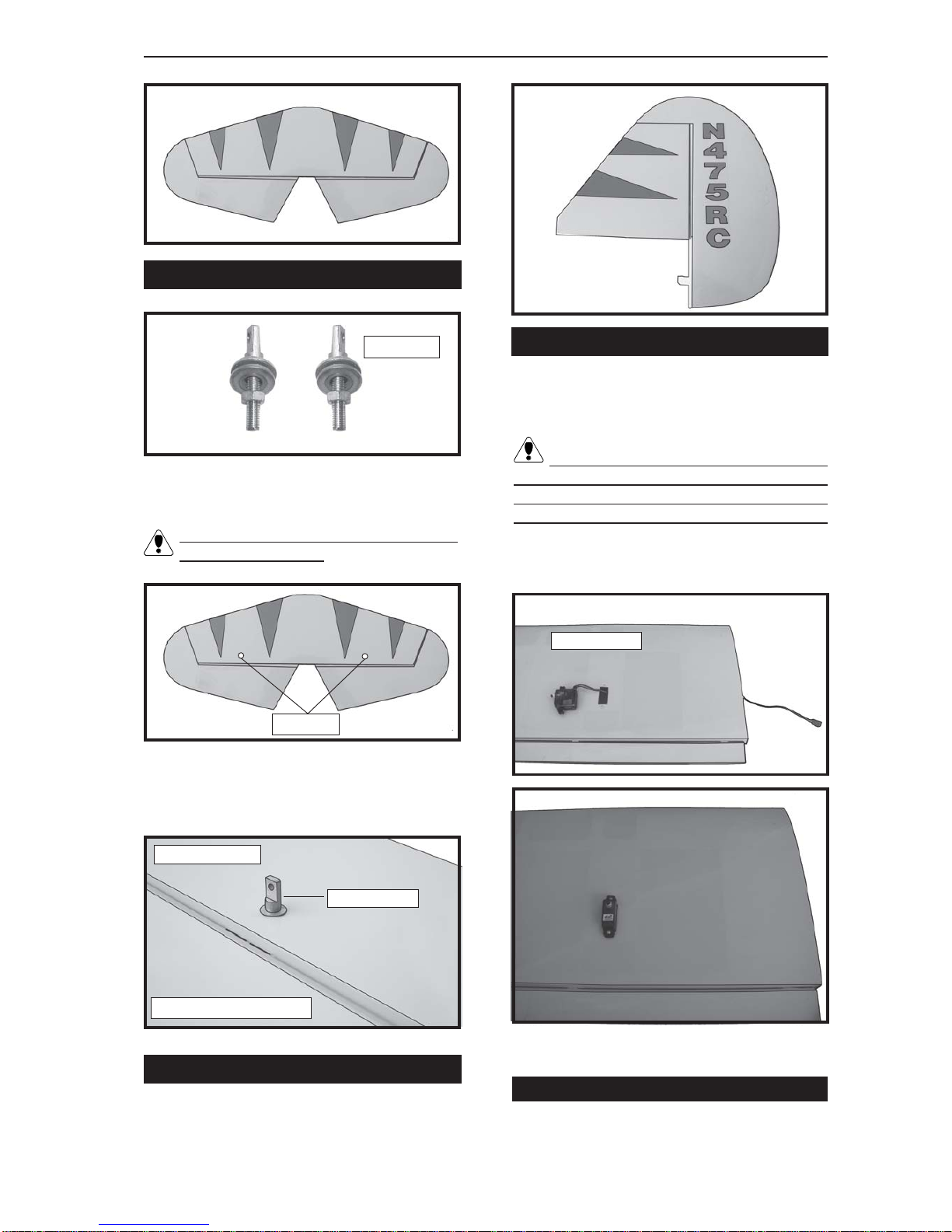
Note:
The control surfaces, including the
ailerons, elevators, and rudder, are
prehinged with hinges installed, but the
hinges are not glued in place. It is
imperativethatyou properlyadherethe
hingesinplace perthesteps thatfollow
using a high-quality thin C/A glue.
Note:
Note:

5
3x20mm.
HINGING THE RUDDER.
Glue the rudder hinges in place using the
same tectniques used to hinge the ailerons.
TURNBUCKLE INSTALLATION.
Theholelocationofturnbucklesshowninpic-
ture below .
The mounting holes of turnbuckle was
pre-drilled at factory.
Installing theturnbucklefor tailstrutof hori-
zontal fin as same as pictures below.
32mm.
Horizontal fin bottom.
Turnbuckle.
Tail fin bottom.
AILERON SERVOS.
Attach the thread to the servo lead and
carefully thread it though the wing.
2)Secure the servos with the screws pro-
vided with your radio system.
Because the size of servos differ, you
mayneed toadjustthesizeoftheprecutopen-
ing in the mount. The notch in the sides of
themountallowthe servoleadtopassthrough.
AILERON LINKAGE.
1) Using a ruler & pen to draw a straight
line as picture below.
wing botton.
1) Install the rubber grommets and brass
collets onto the aileron servo. Test fit the
servo into the aileron servo mount.

SPACE WALKER II Instruction Manual
6
2) Locate the two nylon control horns, two
nylon control horn backplates and four
machine screws.
3) Position the aileron horn on the bottom
side of aileron. The clevis attachment holes
should be positioned over the hinge line.
ControlHorn.
MountingScrews. Mounting Plate.
5) Mount the control horns by inserting the
screws through the control horn bases and
aileron halves, then into the mounting
backplates. Do not overtighten the screws or
the backplates may crush the wood.
4) Using a 1mm drill bit and the control
horns as a guide, drill the mounting holes
through the aileron halves.
6) Connect the linkage as shown and se-
cure the control wire with a wire keeper.
Servo arm.
Wire keeper.
2mm X 20mm.

7
Because the size of servos differ, you
mayneed toadjust thesize ofthe precutopen-
ing in the mount. The notch in the sides of the
mount allow the servo lead to pass through.
1) Locate and cut out the covering film
fromtheservo holesinboth sidesoffuselage.
FUSELAGE SERVO INSTALLATION.
3)Securethe servoswiththe screws pro-
vided with your radio system.
2) Installtherubber grommetsandbrass
collets onto the elevator servo. Test fit the
servo into the elevator servo mount.
Repeat the procedure for the other ai-
leron servo.
Rightside.
Remove covering.
HORIZONTALSTABILIZER.
1) Using a ruler and a pen, locate the
centerlineofthehorizontalstabilizer,atthetrail-
ing edge, and place a mark. Use a triangle
and extend this mark, from back to front,
across the top of the stabilizer. Also extend
thismarkdown thebackof thetrailingedge of
the stabilizer.
2)Usingamodelingknife, carefullyremove
thecoveringatmountingslot ofhorizontalsta-
bilizer ( both side of fuselage).
3) Slide the stabilizer into place in the pre-
cut slot in the rear of the fuselage. The stabi-
lizer should be pushed firmly against the front
of the slot.
4) With the stabilizer held firmly in place,
use a pen and draw lines onto the stabilizer
where it and the fuselage sides meet. Do this
on both the right and left sides and top and
bottom of the stabilizer.
5) Remove thestabilizer. Usingthelines
youjustdrew asaguide, carefullyremovethe
covering from between them using a model-
ingknife.
Pen.
Center line.
Elevator servo.
Rightside.
Left side.
Rudder servo.
Elevator servo.

SPACE WALKER II Instruction Manual
8
6) When you are sure that everything is
alignedcorrectly, apply C/Aglueto thetop and
bottom of the stabilizer mounting area and to
the stabilizer mounting platform sides.
VERTICAL STABILIZER INSTALLATION.
Hinge.
1) Using a modeling knife, remove the
covering from over the precut hinge slot cut
intothe lowerrear portionof thefuselage. This
slot accepts the lower rudder hinge.
2) Glue the vertical fin in place using as
sameastechniquesusedtoinstallingthehori-
zontal fin.
Hingeslot.
Whencuttingthrough thecovering to re-
moveit,cutwith only enoughpressureto only
cut through the covering itself. Cutting into
the balsa structure may weaken it.
Removecovering.
When cutting through the covering to re-
moveit,cutwith only enoughpressureto only
cut through the covering itself. Cutting into
the balsa structure may weaken it.
3) Slide the vertical stabilizer back in
place. Using a triangle, check to ensure that
theverticalstabilizer isaligned90º tothehori-
zontal stabilizer.
Removecovering.
Pen.
90º
Vertical
Stabilizer.
Horizontal
Stabilizer.

9
Elevator control horn.
Control horn installationassame as method
of aileron wing. See pictures below.
CONTROL HORN INSTALLATION.
Pushrod install as same as method of
pushrod of aileron. See pictures below.
PUSHROD INSTALLATION.
Rudder control horn.
Elevator control horn.
INSTALLING TAIL STRUT SYSTEM.
C/Aglue.
Pushrod.
Pushrod.
The tail strut system assembly follow
pictures below.
Plastic trap.
hinge.
C/AGlue.

SPACE WALKER II Instruction Manual
10
1)Set the tail wheel assembly in placeon
the plywood plate. The pivot point of the tail
wheel wire should be even with the rudder
hinge line and the tail wheel bracket should
be on the plywood plate.
3) Secure the tail wheel bracket in place
using two 3x10mm wood screws. Be careful
not to overtighten the screws.
2) Using a pen, mark the locations of the
two mounting screws. Remove the tail wheel
bracket and drill 1mm pilot holes at the loca-
tions marked.
MOUNTING THE TAIL WHEEL.
1) Align the tail wheel wire so that the wire
is parallel with the bottom of the rudder. The
controlclasphas a predrilledholethrough the
topofit. Slidethishole ontothe tailwheelwire
while sliding the clasp over the bottom of the
rudder.
3) While holding the clasp firmly in place,
use a pen and outline the clasp onto the rud-
der.
4) Remove the clasp, and using a model-
ing knife, remove the covering from inside the
lines you drew. Use 220 grit sandpaper and
carefullyroughenthe inside surfaceofthe ny-
lon clasp.
5) Slide the clasp back into position and
carefullyglueitintoplaceusingKwikBondThin
C/A. Holdthe claspin placeuntilthegluecom-
pletely cures. Secure by 1 machine
screw.
MOUNTING THE CONTROL CLASP.
2)Using arulerand apenplace amarkonto
the bottom of the rudder. The back edge of
theclaspshouldlineupwiththismark.Youmay
find it necessary to bend the tail wheel wire
down slightly so it lines up with the clasp with-
outbinding.
Controlclasp.
2MM x12 MM.
Machine Screw
3x12mm.
Plastic trap.

11
1) Assembleandmountingthewheelpants
as shown in the following pictures.
WHEELAND WHEEL PANTS INSTALLA-
TION.
2) Follow diagram below for wheel pant
installation:
WheelCollar.
Axle.
Wheel. Nut.
Wheel Pant.
LandingGear.
Nut.
(2)Washer.
8mm.
3) You have to trim each axle using a tool
cutting and cut-off wheel.
Caution when cutting the axles and
wear protective goggles.
46mm
Landinggear.
(2)WheelCollar.
Axle.
Wheel. Nut.
Nut.
(2)Washer.

SPACE WALKER II Instruction Manual
12
Motor.
Blindnut.
MOTOR BOX.
INSTALLING ELECTRIC MOTOR.
There are 2 mouting box for your option. It is
depended your motor size.
1) The blind nuts for securing the landing
geararealready mountedinside thefuselage.
2) Using the hardware provided, mount
the main landing gear to the fuselage.
Repeat the process for the other wheel.
INSTALLING THE MAIN LANDING GEAR.
4) A drop of C/A glue on the wheel collar
screws will help keep them from coming lose
duringoperation.
4x20mm.
Epoxyglue.
MOTOR BOX.
Diameter 4.5 mm.

13
INSTALLING THE BATTERY.
See pictures below:
See pictures below.
Slidethe fiberglasscowlover theengine and
lineupthebackedgeofthecowlwiththemarks
you made on the fuselage then trim and cut.
3X10MM.
Secure the cowl with the screw provide with
hardware.
See pictures below.
Trim and cut.
Glue.
Speed control.
Battery.
Tie wrap or rubber band.
COWLING INSTALLATION.
DUMMY ENGINE INSTALLATION.

SPACE WALKER II Instruction Manual
14
2 x 8mm Machine Screw.
ATTACHMENT WING - FUSELAGE.
Bolt the wing to fuselage.
Receiver.
Tie wrap.
Wing tube.
INSTALLING THE RECEIVER.
PILOT INSTALLATION.
WIND SHIELD INSTALLTION.
1 Removethefastening wireassame aspic-
ture below.
2 Glue the pilot in to the position.
Antennawire.
Glue.
Glue.
Fastening wire.

15
Insert two wing panels as pictures below.
Wing bolt.
1) It is critical that your airplane be bal-
anced correctly. Improper balance will cause
yourplanetolosecontrol andcrash. The cen-
ter of gravity is locate 7.5-8cm back from
theleadingedgeofthewing,measuredatwing
tip.
BALANCING.
7.5 - 8cm.
2) If the nose of the plane falls, the plane
is nose heavy. To correct this first move the
battery pack further back in the fuselage. If
this is not possible or does not correct it, stick
small amounts of lead weight on the fuselage
sides under the horizontal stabilizer. If the tail
of the plane falls, the plane is tail heavy. To
correctthis,movethebattery andreceiverfor-
ward orif this is not possible, stick weight onto
the firewall. When balanced correctly, the air-
plane should sit level or slightly nose down
when you lift it up with your fingers.
CONTROL THROWS.
1) We highly recommend setting up the
SPACE WALKER II using the control throws
listed at right. We have listed control throws
for both Low Rate (initial test flying/sport fly-
ing) and High Rate (aerobatic flying).
3) When the elevator, rudder and aileron
control surfaces are centered, use a ruler and
check the amount of the control throw in each
surface. The control throws should be
measured at the widest point of each sur-
face!
2) Turnonthe radiosystem,and withthe
trim tabs on the transmitter in neutral, center
the control surfaces by making adjustments
totheclevisesoradjustableservoconnectors.
The servo arms should be centered also.
INITIALFLYING/SPORT FLYING
Ailerons: 3/16” up 3/16” down
Elevator : 3/8” up 3/8” down
Rudder : 1 right 1 left
Ailerons: 3/8” up 3/8” down
Elevator : 1” up 1” down
Rudder : 2” right 2” left
Do not use the aerobatic settings for
initialtestflyingorsportflying.
AEROBATIC FLYING

SPACE WALKER II Instruction Manual
16
FLIGHT PREPARATION.
A) Check the operation and direction of
the elevator, rudder, ailerons and throttle.
B) Plug in your radio system per the
manufacturer's instructions and turn every-
thingon.
D) Check the rudder. Looking from be-
hindtheairplane, move therudderstick to the
right. Theruddershouldmoveto theright. If it
does not, flip the servo reversing switch on
your transmitter to change the direction.
C) Check the elevator first. Pull back on
theelevatorstick. The elevatorhalvesshould
move up. If it they do not, flip the servo re-
versing switch on your transmitter to change
the direction.
4) By moving the position of the adjust-
able control horn out from the control surface,
you will decrease the amount of throw of that
control surface. Moving the adjustable con-
trol horn toward the control surface will in-
crease the amount of throw.
PREFLIGHT CHECK.
1) Completely charge your transmitter
and receiver batteries before your first day of
flying.
2) Check every bolt and every glue joint
in the SPACE WALKER II to ensure that ev-
erything is tight and well bonded.
3) Double check the balance of the air-
plane. Do this with the fuel tank empty.
4) Checkthecontrol surfaces. Allshould
move in the correct direction and not bind in
any way.
5) If your radio transmitter is equipped
withdualrate switchesdoublecheck thatthey
are on the low rate setting for your first few
flights.
6) Check to ensure the control surfaces
are moving the proper amount for both low
and high rate settings.
8) Properlybalancethe propeller. An out
of balance propeller will cause excessive vi-
bration which could lead to engine and/or air-
frame failure.
We wish you many safe and enjoyable
flights with your SPACE WALKER II.
7) Check the receiver antenna. It should
be fully extended and not coiled up inside the
fuselage.
E)Check thethrottle. Movingthe throttle
stick forward should open the carburetor bar-
rel. Ifit doesnot, fliptheservoreversingswitch
on your transmitter to change the direction.
F) From behind the airplane, look at the
aileronontherightwinghalf. Movetheaileron
stickto theright. Therightaileronshouldmove
upandthe otheraileron shouldmovedown. If
it does not, flip the servo reversing switch on
your transmitter to change the direction.
Table of contents
Other Lindinger Toy manuals
Popular Toy manuals by other brands

Horizon Hobby
Horizon Hobby UMX Ultrix instruction manual

Fisher-Price
Fisher-Price ColorMe Gemz Bracelet Set N1144 instruction sheet

Fisher-Price
Fisher-Price GRR01 instructions

arf
arf AeroPet 50 instruction manual

Kettler
Kettler Kettcar KABRIO Assembly instructions

LEXIBOOK
LEXIBOOK WORD SCHOOL BILINGUAL ENGLISH/GERMAN instruction manual