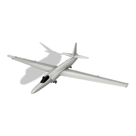
rc3Dprint Micro Velocity User manual

J
PRINTING AND
ASSEMBLY
INSTRUCTION
BOOK
Micro Velocity

THANK YOU
Thank you for downloading this Micro Velocity XL. These models take many hours of work
to make available to you so please don’t share the STL files with others. Send them to
www.rc3print.com where they can download the models themselves. This enables me to
continue to develop new models to make them available for download.
This document aims to help you print and assemble your aircraft. Our designs are made to
be simple, this model is designed explicitly with LW-PLA in mind, so it incorporates carbon
tube spars. If you print it from regular PLA it will obviously be heavier and you should take
this into account.
3D printers often have many differences so you may need to tweak settings to get the best
results.
Included in the document you will find Cura profiles and layouts for each part and assembly
instructions. Most of the components in the design are solid bodies, this has some advantages
over hollow bodies in that you can adjust some settings such as wall thickness, infill
percentage, etc. As such we recommend using Cura to slice the files though it is not
required for this model. The walls of these solid bodies are single line 0.4mm thickness to
reduce weight. As you are printing and assembling the model yourself we take no liability
for damage or loss resulting from your use of these files. Please fly responsibly and follow all
local laws.
Share your results on Instagram, Facebook, or by email and tag @rc3dprint for discount
codes on future orders.

PARTS LIST
REQUIRED
I recommend UMX electrics, specifically from the UMX Cessna 182, for this model however
you can use any lightweight rx/esc and servos you like.
RX ESC and integrated servo - EFLA5864
SPMA3065 Programming cable
LIPO 2S 7.4v - EFLB2802S30
Prop adapter (long) - EFLU1168
Prop 5x2.5 - EFLUP050275
Motor BL180 3000Kv - EFLUM180BLB
2 x Micro linear throw 2.3g servos (SPMSA2030L)
LW-PLA from Colorfabb
0.5mm piano wire
2mm Outside diameter carbon tube - 2 x 380mm 1 x 340mm

INCLUDED STL. FILES
FUSELAGE
WING

CANARD
VERTICAL STAB

OTHER PARTS

SPECIFICATIONS
Wing Span & Area
710mm span
Flying Weight
169g
Wing Loading
16.9g/m 5.6oz/sq ft
Wing Cube Loading
5.4
Channels
3
Centre of Gravity - 8mm
behind fuselage join
709.93
452.69

PRINTING PROFILES
* If printing in LW-PLA from Colorfabb we recommend following the calibration process
suggested by the manufacturer regarding nozzle temp and flow, below are suggestions
LW-PLA PROFILE
Save this profile as LW-PLA. Changes to generic ‘Low Quality’ PLA profile.
PLA AND TPU PROFILE
You can use your standard settings for the parts printed in TPU and PLA, as they are not
structural.
Layer height
0.24mm
Wall Thickness
0.4mm
Wall line count
1
Top/Bottom Pattern
Lines
Infill Density
3
Infill Pattern
Cubic
Flow
50%
Printing Temperature
240C*
Build Plate Temperature
60C (optional)
Fan Speed
20% Maximum
Generate Support
No
Build Plate Adhesion
Brim or Skirt

A WORD ON RETRACTIONS
With regular PLA a common problem is under extrusion at layer change - to fix this increase
the setting extra prime amount in Cura.
With LW-PLA it is recommended to switch retractions OFF since trying to retract the
foaming filament can cause problems. If you need to fix under extrusion you can still use the
method above but will need to turn retractions ON and set the retraction distance to 0mm.

ASSEMBLY
1. THROUGHOUT THE BUILD, ADHESIONS SHOULD BE
CAREFULLY REMOVED AND FACES TO BE GLUED
TOGETHER SHOULD BE SANDED FIRST TO ENSURE
GOOD CONTACT. THIS IS CRITICAL. TIME TAKEN
HERE WILL ENSURES YOUR AIRCRAFT IS STRONG.
FUSELAGE
-Glue to the two fuselage pieces together
WINGS
-Cut your carbon tube to size, you can then build your wing around this. It doesn’t have to
be glued in place however, this is so that it is easier to remove it incase you have a crash
and want to use it again. Because of blobs and expansion you will need to carefully clear
out the ends of the holes for the carbon rod in the wing pieces.
-Starting from the root build the wings sections up using the carbon tube to help with
alignment. You want to be able to keep the tube free so that you can position it for the
end pieces. Don’t worry about the ailerons yet.
-Glue both parts of the vertical stabs together and clean out the hole for the spar. Tiy can
then add this on the the end of the wing with the carbon in place.
-Clean up the holes for the TPU hinges in both the aileron and wings.
-The carbon spar can now slide into the fuselage and the wings glued on. TAKE CARE TO
ALIGN THE WING CORRECTLY.

-Glue together the aileron pieces, careful not to have any glue fill up the hinge space.
-When gluing the hinges into he wings you can line the aileron up with the wings to give
enough space for the hing to move. The front of the hinge should be about 1mm away
from the wing.
CANARD
-With the carbon tube to help, glue the tips onto the canards.
-The canard is installed with the carbon tube running through the fuselage. Try to make
sure the fuselage isn’t ‘pinched’ when you slide the tube through it.
-Glue the canard to the fuselage with the carbon tube in place. TAKE CARE TO ALIGN
THE CANARD CAREFULLY.
MOTOR MOUNT
-The motor mount is glued onto the aft firewall of the fuselage, make sure the hole for the
mounting screw is facing up. Insert the motor and secure with a screw.
-Different types of motor can be mounted onto the firewall if needed.
COWLING AND CANOPY
-Glue together the two canopy sections. Clean the print at the nose section around the
latch so that it will fit.
-Glue the motor cowling in on to the firewall.
-To fit the canopy, have the plane face you, touching your stomach. Place the front latch of
the canopy into position and gently squeeze from the back. You can ease the two rear
latches under the firewall. To remove you do the same only gently ease up the middle of
the canopy edges.
MOUNTING SERVOS AND CONTROL RODS

-The rx/esc should be mounted onto the tray ( I used
double sided foam tape) then the tray screw into place
as far forward as you can (checking the wires reach the
motor). This means you can move the rx between
models).
-The servos should be mounted onto the servo trays.
Make your control rods and attach them to the elevons
making sure you go through the small holes on the
fuselage sides. You may need to clean up the holes a
little.
-Attach the control rods to your servos and screw your
servos down with the elevons in the neutral position.
-The canopy will need to have a notch cut out (located where the hole is) to go over the
control rod. It will also need the tabs cut back at the end to fit over the firewall.

PROGRAMMING
If you are using the Cessna 182 UMX board
(EFLU5864) then you will need to reprogram
the board for elevon mixing. Whilst this can be
achieved inside your transmitter, the AS3X will
interfere with your controls, I.e. a sensed pitch
will be corrected with what it thinks is the
elevator and cause a roll!?
Using the SPMA3065 cable and the Spectrum
programming software you can easily create the
mixes, one for roll and one for pitch.
You will need to create a plug for the programming cable as the one on the adapter is the
wrong size. I simply use a spare micro servo plug.
Plug into the the programming port on the rx. The orange
wires should always be to the antenna side. Connect the usb
to your PC and plug in the models battery.
I won’t go into AS3X tuning here, there is plenty of
information from those more knowledgeable than me
online. I have the AS3X gains turned off.

To set up the elevon mixing follow the settings in the screenshots


ADVICE FOR MAIDEN FLIGHT
Make sure the control surfaces are moving correctly! The battery should be positioned such
that it won’t move, I tend to use sticky velrco for this.
Check the CG. Check the CG again! The CG should be located 5mm to 10mm behind the
fuselage join. You may need to add ballast or use a larger battery to the nose.
If hand launching, be careful of your hand on the prop, you can launch holding the front of
the wing root rather than the fuselage to keep your hand clear. For the maiden it is advisable
to have a friend help.
Have fun!

CURA COMPONENT PLACEMENT
COWLING
“Spiralize outer contour”
FUSELAGE FRONT
FUSELAGE BACK
If using a motor that will need to
affix to the firewall, increase the
thickness of the bottom layers.

VERTICAL STAB TOP
Unique Setting: None
VERTICAL STAB BOTTOM
Unique Settings: None
CANOPY 1
Unique Settings: None

CANOPY 2
Unique Settings: None
WING 1
Unique Settings: None
WING 2
Unique Settings: None

WING 3
Unique Settings: None
CANARD TIP
Unique Settings: None
CANARD
Unique Settings: None
This manual suits for next models
1
Table of contents
Other rc3Dprint Toy manuals

rc3Dprint
rc3Dprint PIAGGIO AVANTI 2 User manual

rc3Dprint
rc3Dprint QUICKIE User manual

rc3Dprint
rc3Dprint PILATUS PC-6 PORTER User manual
rc3Dprint
rc3Dprint MICRO PEREGRINE FLYING WING User manual

rc3Dprint
rc3Dprint ER-2 User manual

rc3Dprint
rc3Dprint SkiGull User manual

rc3Dprint
rc3Dprint Grumman X-29 User manual
Popular Toy manuals by other brands

Basher
Basher NITRO CIRCUS instruction manual

Great Little Trading
Great Little Trading Starbeans Coffee Shop quick start guide

Eduard
Eduard Ju 88G-1 Night Fighter quick start guide

ROBBE
ROBBE ASW 15 Assembly and operating instructions

LeapFrog
LeapFrog Shapes & Sharing Parent guide & instructions

Little Tikes
Little Tikes COZY TRUCK 642319M Assembly instructions